K40 LD5500 User manual
TM
ELECTRONIC
S
INSTALLATION INSTRUCTIONS
LASER DEFUSERPLUS
P
ARTS
K
IT
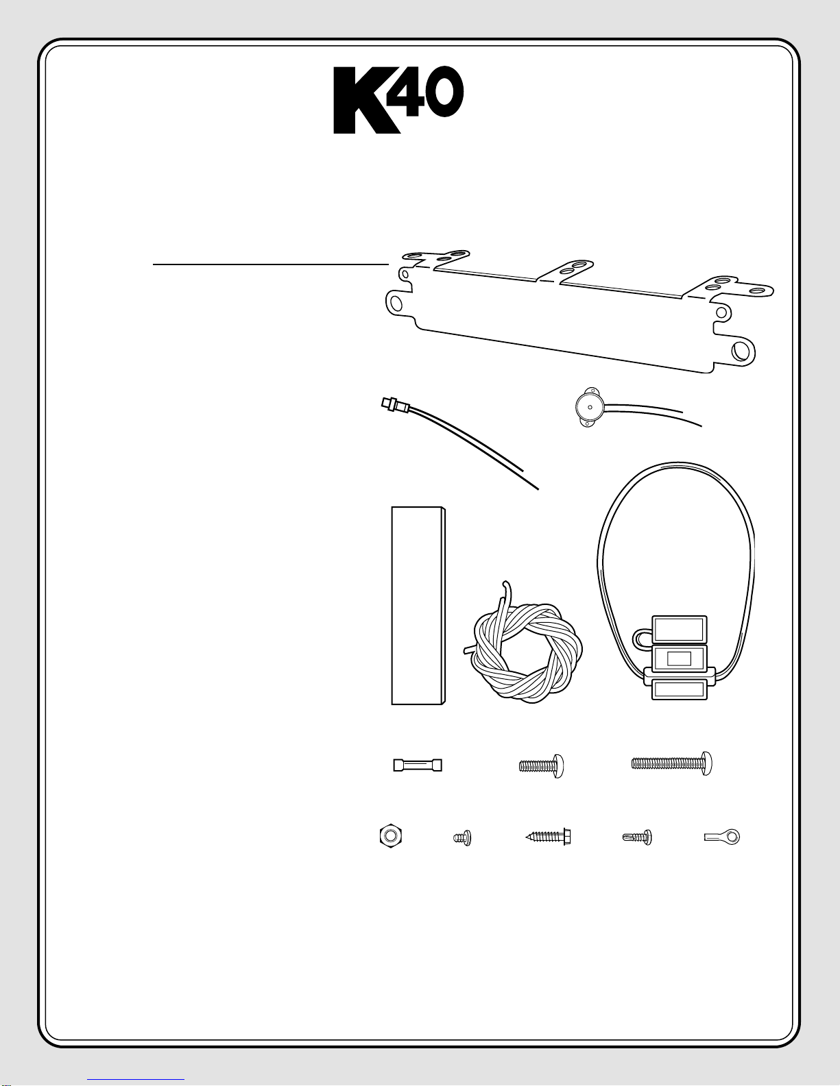
Parts Kit includes the following:
A- (1) Universal Mounting Bracket
B- (1) Red L.E.D. Laser Alert Light
C- (1) Piezo Beeper w/ “O” Ring Tape
D- (1) Double Stick Tape Strip
E- (2) 36” - 20 ga. Grounding/Power Wires
F- (1) 3 AMP Fuse Assembly
G- (4) Barrel Connectors
H- (2) 1” - 1/4” x 20 Nylon Bolts
I- (2) 1 1/2” - 1/4” x 20 Nylon Nuts
J- (8) 1/4” x 20 Nylon Bolts
K- (2) #6 x 1/4” Screws
L- (3) #10 x 3/4” Screws
M- (1) 1/2” Self Tapping Screw
N- (1) 22-16 ga. Ring Terminal
IMPORTANT - PLEASE READ BEFORE INSTALLING
When installing the Laser DefuserPlus outside of the system’s license plate frame, the unit should be mounted as
close to the center of the vehicle as possible, without obstruction. The mounting location of the Laser DefuserPlus
is important, as police laser gun operators are trained to aim for the flat, reflective surface of a targeted vehicle’s
front license plate. In states that do not require a front license plate, operators will traditionally aim for the front,
center of the vehicle. This procedure allows the operator to effectively "bounce" the laser signal back to the gun
to calculate the vehicle’s speed.
A
C
E
D
F
GHI
JK L M
B
N
L
ASER
L.E.D. L
IGHT
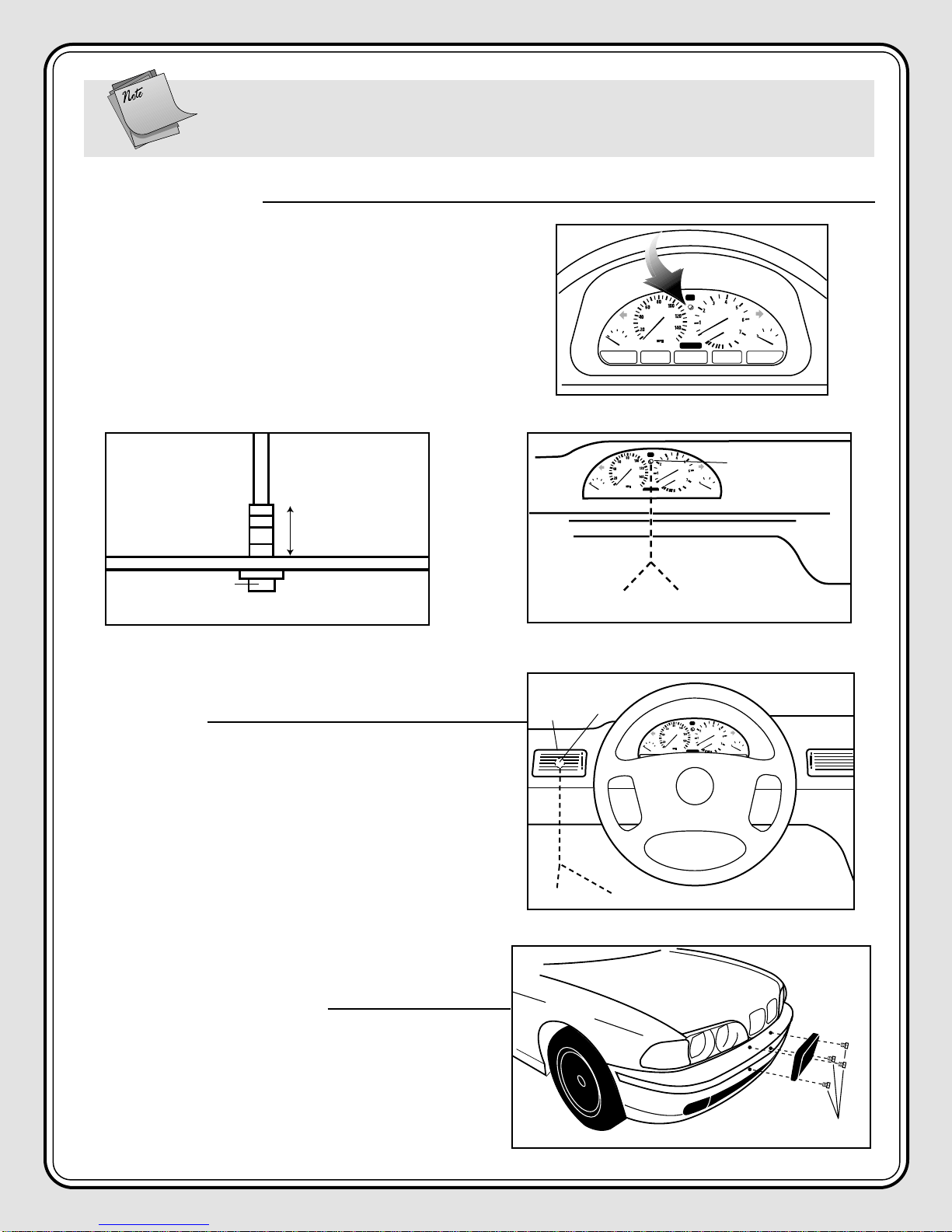
1. For best visibility, choose a mounting location for the laser L.E.D.
as close to the vehicle gauges as possible. See diagram A1.
2. Check for proper clearance behind the area where the L.E.D.
will be installed (approximately 1”), and drill a 3/16”hole in the
chosen location. See diagram A2.
3. Route the L.E.D. wires under the dash per diagram A3 and
connect according to the appropriate block diagram.
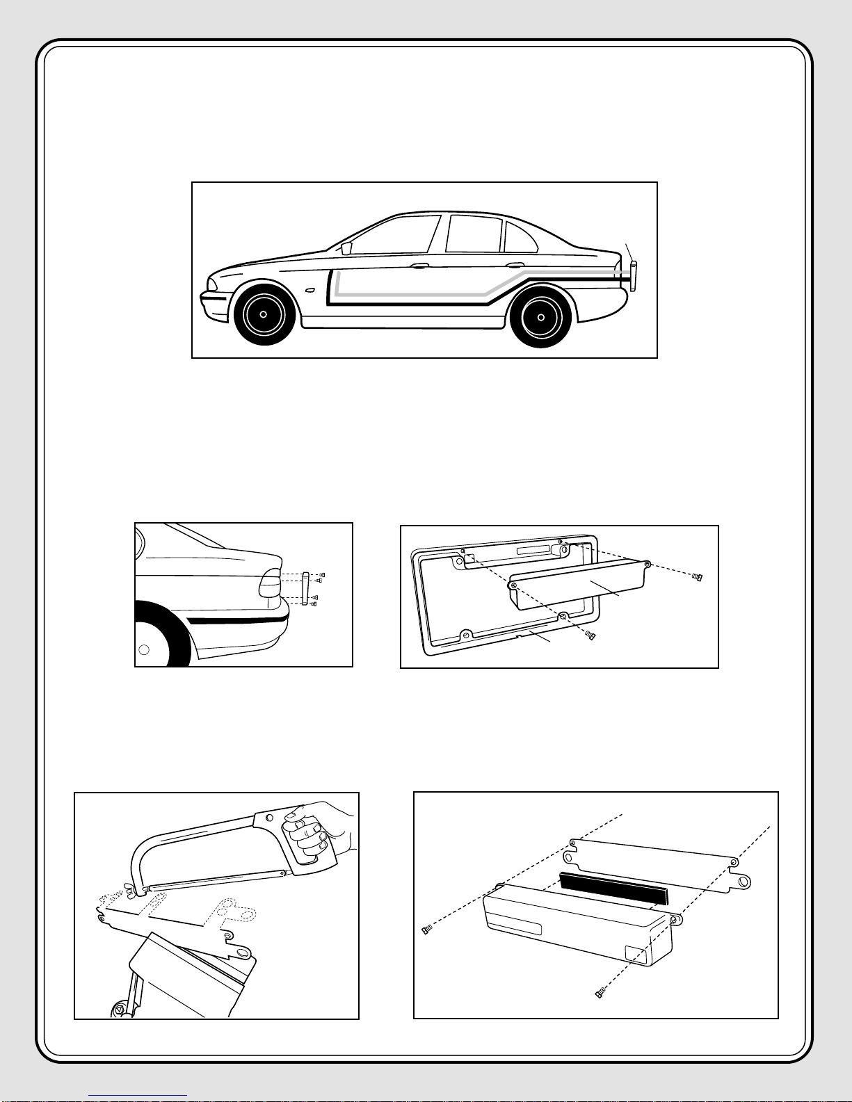
DIAGRAM C1
F
RONT
L
ASER
D
EFUSER
P
LUS
LICENSE PLATE MOUNT
1. Remove the mounting bolts and any existing frame or
cover from the license plate. Remove license plate.
See diagram C1.
FACTORY LICENSE
PLATE BOLTS
Note: When integrating the Laser DefuserPlus with the K40 remote radar system, the Laser DefuserPlus
will utilize the same warning light/speaker(s) as the K40 remote. Therefore, you will not
need to install the red L.E.D. alert light or piezo beeper that come with the Laser DefuserPlus.
1"
DIAGRAM A1
DIAGRAM A2 DIAGRAM A3
ALERT
LIGHT
RED ALERT L.E.D.
GREY L.E.D.
WIRE BLACK L.E.D.
WIRE
P
IEZO
B
EEPER
1. For maximum audio output and concealment, mount the
piezo beeper in the driver’s left air vent. See diagram B1.
2. Use the supplied double stick “O”ring tape
to mount the piezo beeper.
3. Route the piezo beeper wires through or under the dash
per diagram B1 and connect according to the appropriate
block diagram.
DIAGRAM B1
PIEZO
BEEPER
LEFT AIR
VENT
RED WIRE
BLACK WIRE

2. Position the Laser DefuserPlus around the existing front license
plate and mount it against the factory license plate bracket.
Use the existing mounting bolts or K40 nylon bolts to secure the
DefuserPlus frame and license plate to the bracket.
See diagram C2.
3. Route the black and clear zip cord wires into the engine compartment either through the grill or under the
bumper. See diagram C3.
4. Pass both the black and clear zip cord wires towards the vehicle’s firewall and through an existing rubber
grommet into the vehicle’s interior. See diagram C4.
5. Connect wires according to the appropriate block diagram and insert the 3 amp fuse into the fuse holder.
Secure the watertight fuse cover. Turn on the ignition key to verify operation.
Caution:
Avoid hot or moving parts.
Note: For optimum per-
formance, the DefuserPlus
must be mounted parallel to
the ground. Use the supplied K40
nylon nuts and bolts to correct the
mounting angle of the DefuserPlus
either up or down as needed.
On some vehicles, it may be necessary
to adjust or reposition the factory
license plate bracket to achieve the
parallel mounting.
On vehicles that have only one set of
bracket mounting holes, it is recom-
mended that the Laser DefuserPlus
and the license plate be bolted
together to eliminate any vibration.
DIAGRAM C2
DIAGRAM D1
DEFUSERPLUS
FRAME
DEFUSERPLUS
MODULE
SCREW
UNIVERSAL MOUNTING BRACKET
1. Choose a mounting location inside the lower air intake vent or
grill that has a clear, unobstructed view of the road.
2. Separate the Laser DefuserPlus module from the license plate
frame by removing the two screws on the backside of the
frame. See diagram D1.
DEFUSERPLUS
FACTORY
MOUNTING
LOCATION
MOUNTING NUTS
LICENSE
PLATE
LICENSE PLATE
LASER DEFUSERPLUS
BOLTS
CLEAR
THROUGH
FIREWALL
BLACK
DIAGRAM C3
RUBBER
GROMMET
TO VEHICLE
INTERIOR
BLACK
CLEAR
DIAGRAM C4
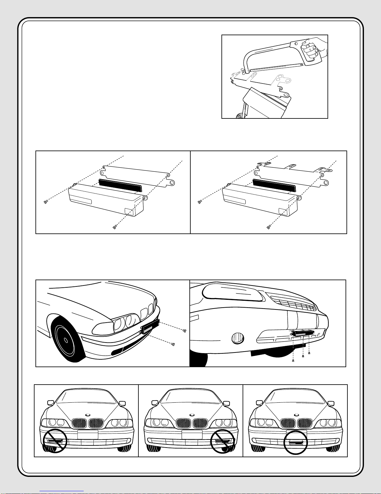
DIAGRAM D5
DIAGRAM D4
5. Install the Laser DefuserPlus to the desired mounting surface using included 3/4”screws or nylon mounting nuts
and bolts. See diagram D4. For optimum performance, make sure DefuserPlus is mounted parallel to the ground
as close to the center of the vehicle as possible. See diagram D5.
BRACKET
TAPE
1/4” SCREW
DEFUSER
BRACKET
TAPE
DEFUSER
1/4” SCREW
DIAGRAM D3
WITHOUT
HORIZONTAL
TABS
WITH
HORIZONTAL
TABS
3. Determine which holes on the universal mounting brack-
et will be used to mount the Laser DefuserPlus to the car.
Remove the unused mounting holes on the bracket as
needed. See diagram D2.
DIAGRAM D2
4. Apply the supplied double stick tape directly to the Laser DefuserPlus and position the DefuserPlus to the
universal mounting bracket with the included 1/4”screws. See diagram D3.
INCORRECT INCORRECT CORRECT
WITHOUT
HORIZONTAL
TABS
WITH
HORIZONTAL
TABS
CLEAR
THROUGH
FIREWALL
BLACK
RUBBER
GROMMET
TO VEHICLE
INTERIOR
BLACK
CLEAR
6. Route the black and clear zip cord wires into the engine compartment either through the grill or under the
bumper. See diagram D6.
7. Pass both the black and clear zip cord wires towards the vehicle’s firewall and through an existing rubber
grommet into the vehicle’s cockpit. See diagram D7.
8. Connect wires according to the appropriate block diagram and insert the 3amp fuse into the fuse holder.
Secure the watertight fuse cover. Turn on the ignition key to verify operation.
DIAGRAM D6
DIAGRAM D7
R
EAR
L
ASER
D
EFUSER
P
LUS
LICENSE PLATE MOUNT
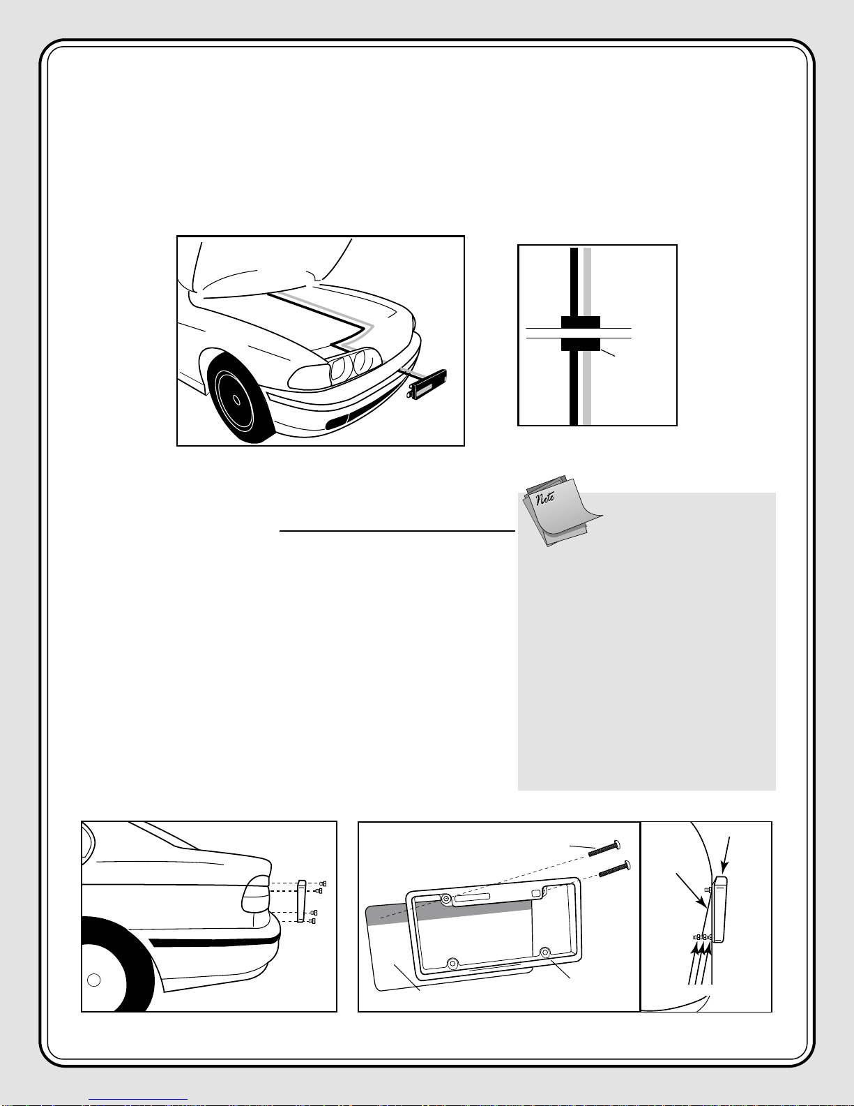
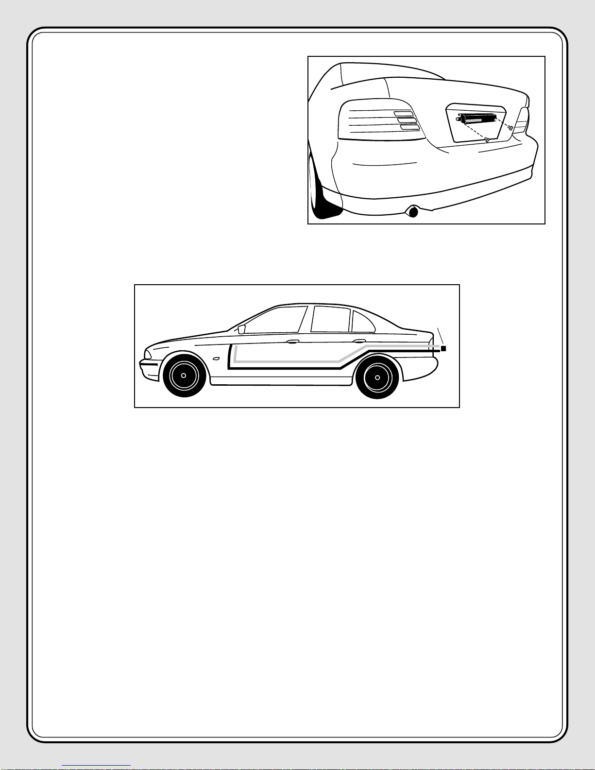
1. Remove the mounting bolts and any existing frame or cover
from the rear license plate. Remove license plate.
See diagram E1.
2. Position the Laser DefuserPlus around the existing rear license
plate and mount it against the factory license plate bracket.
Use the existing mounting bolts or K40 nylon bolts to secure
the DefuserPlus frame and license plate to the bracket.
See diagram E2.
DIAGRAM E2
FACTORY LICENSE
PLATE BOLTS
DIAGRAM E1
Note: For optimum per-
formance, the DefuserPlus
must be mounted parallel to
the ground. Use the supplied K40
nylon nuts and bolts to correct the
mounting angle of the DefuserPlus
either up or down as needed.
On some vehicles, it may be necessary
to adjust or reposition the factory
license plate bracket to achieve the
parallel mounting.
On vehicles that have only one set of
bracket mounting holes, it is recom-
mended that the Laser DefuserPlus
and the license plate be bolted
together to eliminate any vibration.
LICENSE
PLATE
LICENSE PLATE
LASER DEFUSERPLUS
BOLTS
DEFUSERPLUS
FACTORY
MOUNTING
LOCATION
MOUNTING NUTS
3. Route the black and clear zip cord wires into the trunk, through the passenger compartment, along the driver’s
side, and under the dash per diagram E3.
4. Connect wires according to the appropriate block diagram and insert the 3amp fuse into the fuse holder.
Secure the watertight fuse cover. Turn on the ignition key to verify operation.
UNIVERSAL MOUNTING BRACKET
1. Remove the mounting bolts and any existing frame or cover from the rear license plate. Remove license plate.
See diagram F1.
2. Separate the Laser DefuserPlus module from the license plate frame by removing the two screws on the back-
side of the frame. See diagram F2.
DIAGRAM E3
DEFUSER
TO L.E.D. LIGHT
AND PIEZO BEEPER
FACTORY LICENSE
PLATE BOLTS
DIAGRAM F1 DIAGRAM F2
DEFUSERPLUS
FRAME
DEFUSERPLUS
MODULE
SCREW
DIAGRAM F3 DIAGRAM F4
BRACKET
TAPE
DEFUSER
1/4”SCREW WITHOUT
HORIZONTAL
TABS
3. Remove the 3 unused horizontal mounting tabs from the top of the universal mounting bracket. See diagram F3.
4. Apply the supplied double stick tape directly to the Laser DefuserPlus and position the Laser DefuserPlus to the
universal mounting bracket with the included 1/4”screws. See diagram F4.
5. Position the Laser DefuserPlus against the license
plate and mount it to the factory license plate
bracket using the existing mounting bolts or K40
nylon bolts. See diagram F5.
6. Route the black and clear zip cord wires into the
trunk, though the passenger compartment, along
the driver’s side and under the dash per diagram F6.
7. Connect wires according to the appropriate block
diagram and insert the 3amp fuse into the fuse
holder. Secure the watertight fuse cover. Turn on
the ignition key to verify operation.
DEFUSER
TO L.E.D. LIGHT
AND PIEZO BEEPER
DIAGRAM F5
DIAGRAM F6
TM
ELECTRONIC
S
44533 3/02
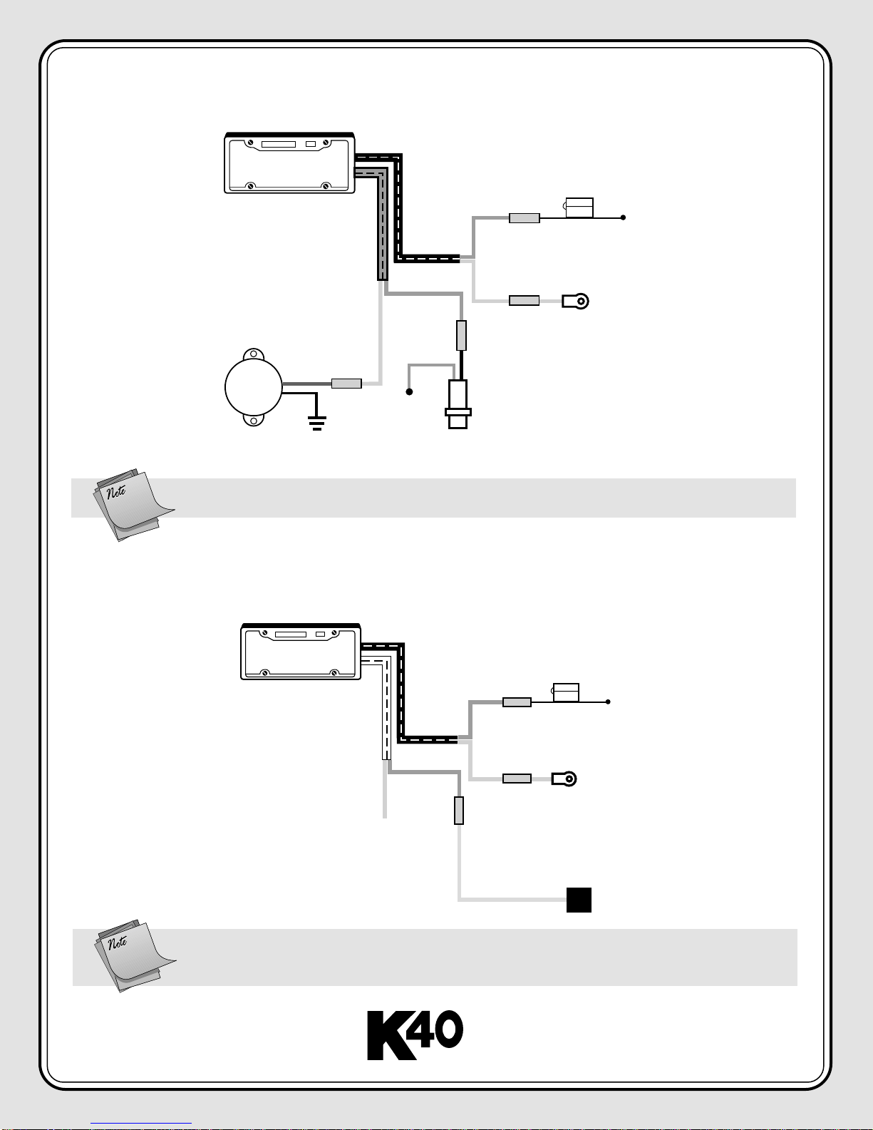
BLACK
ZIP CORD
PIEZO
BEEPER
COPPER
SILVER
3AMP
COPPER
LASER
DEFUSERPLUS
CLEAR
ZIP CORD
BLACK
RED
SILVER
GREY BLACK
LASER
ALERT
L.E.D.
CHASSIS
GROUND
FUSE
CONNECTION
+12V
IGNITION
ON
TO +12 VOLT
IGNITION ON
FUSED SOURCE
LASER DEFUSERPLUS
BLOCK DIAGRAM
Note: When installing front and rear Laser DefuserPlus units,
use a separate 3amp fuse for each Laser Defuser.
LASER DEFUSERPLUS/K40 REMOTE RADAR SYSTEM
INTEGRATION DIAGRAM
BLACK
ZIP CORD
COPPER
SILVER
3AMP
COPPER
LASER
DEFUSERPLUS
CLEAR
ZIP CORD
CHASSIS
GROUND
FUSE
CONNECTION
+12V
IGNITION
ON
K40 REMOTE
RADAR VOLUME
CONTROL MODULE
YELLOW
SILVER
(NOT USED)
Note: When integrating front and rear Laser DefuserPlus units, both of the clear/copper
wires from the two units can be directly connected to the yellow volume control
module wire from the K40 remote Radar Detector.
This manual suits for next models
1
Other K40 Radar Detector manuals


