KAEL DC-MULTISER-1UH-DIN User manual

KAEL Mühendislik Elektronik Tic. ve San. Ltd.Şti.
www.kael.com.tr
DC MULTIMETER and ENERGOMETER
ISO 9001:2008
■
DC Current (with Shunt Resistance)
Programmable (50-100mV)
DC-MULTISER-1UH-DIN
■
DC Current 0-300V dc
■
DC Power
■
DC Energy
■
Relay Output
■
Digital input
■
Pulse Output
■
Analogue Output
(programmable)
■ RS 485 – MODBUS RTU
4-20mA 0-20mA
0-10V 2-10V
0-5V 1-5V
■
DC Current 0-1200V dc
■
Auxiliary Supply Voltage
85-265Vac or 100-300Vdc
■
Auxiliary Supply Voltagei
18-75Vdc
DC-MULTISER-1OH-DIN
DC-MULTISER-1OL-DIN
DC-MULTISER-1UL-DIN
■
■
■
■
■
■
■ ■
■ ■ ■ ■
■ ■ ■ ■
■ ■ ■ ■
■ ■ ■ ■
■
■
■
■
■
■
■ ■
■ ■ ■ ■
■ ■ ■ ■
■ ■ ■ ■
■ ■ ■ ■
1 2 1 1
1 2 1 1
1 2 1 1
1 2 1 1
DC-MULTISER-2UH-DIN
DC-MULTISER-2OH-DIN
DC-MULTISER-2OL-DIN
DC-MULTISER-2UL-DIN
Green Power Measurement Device,
■
Dimensions (105x90x59 mm)
■
■
■
■
■
■
■
■
■
Easy use via menus with shortcuts
■
DC current, voltage and power values can be simultaneously monitored.
■
Four different types of energy measurement as total, positive, negative and difference can
be fulfilled.
■ Secondary part of shunt resistance can be set between 50 mV and 100mV
■ Voltage, current and power alarms
■ Multiple alarms
■ Password protection
Measurements
■ Voltage
■ Current
■ Active Power
■ Active Energy
input and outputs
■ Relay output (1 pc)
■ Pulse output (1 pc )
■ Digital inputs ( 2 pcs )
■ Analogue output ( 1 pc )
■ RS-485 MODBUS-RTU
DC- MULTIMETER and ENERGOMETER MODELS

■
For DC energy management systems
■
For wind and solar energy systems
■
For industrial DC control applications
■
For DC warning systems
■
For vessel and yacht electrical systems
■
For Metallurgy, galvanoplastics and electro analysis industry
1- 1-Before starting the assembly of the device, ambient temperature and
humidity of the assembly location should be checked.
Otherwise the device may get damaged.
Storage Temperature: -10C....+70C
Ambient Temperature: 0C........+50C
Humidity: %15 - %95 (without condensation)
2-It should be taken care to ensure that the switchboard on which the device is to be
mounted should comply with IP20
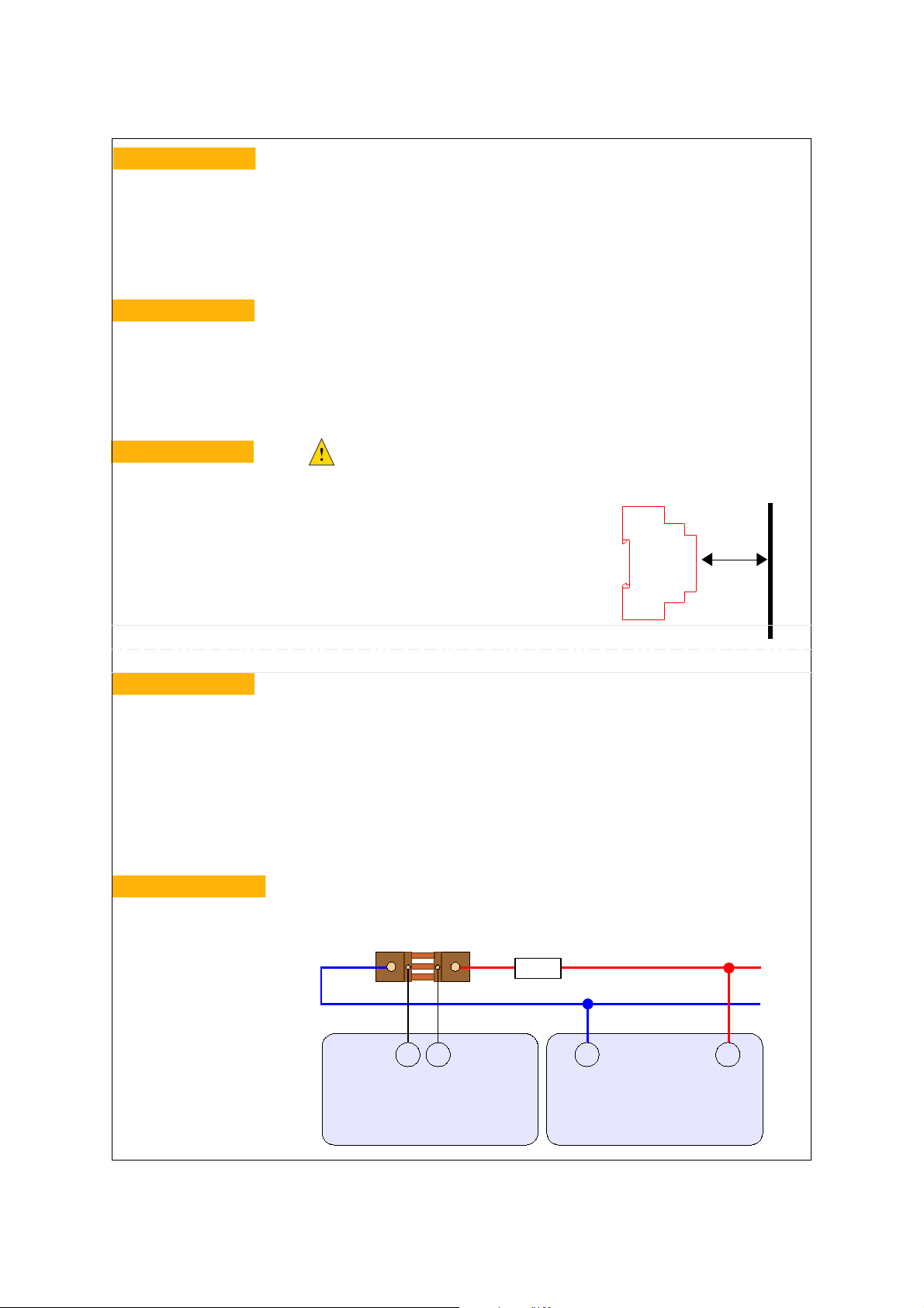
3-The device should be mounted on the assembly rail inside the switchboard.
4-Please allow a clearance of at least 50 mm between the front side of the device
and the switchboard cover or protection sheet.
50 mm
The connections of the device should be made when the device is deenergised.
The device should be connected as shown in the connection diagramme.
Please make the RS485 connection
Please do not energise the device before carrying out a check for all the connections by means of a gauge.
Current and voltage terminals comply with cables with a max. Cross-section of 2,5mm2
Pulse outputs, inputs and RS485 terminals comply with max. 1,5 mm2 cables
CAT5 (category 5) cable is recommended for RS485 connections
If the system presents power quality problems, insulation transformer or EMC filter should be used
for auxiliary power supply.
Switch board cover or
protection sheet
With our DC-MULTISER devices, dc current, voltage, active power and active energy may be measured. Moreover,
double-sided (positive-negative) current may be measured. The device allows the total, positive and negative operation
times to be monitored separately.
Before enabling this device, please read this manual carefully for the safety of both your system and yourself.
Please do not take any actions before contacting our company for any ambiguous matters.
Tel: 0.232.877 14 84 (pbx) Fax: 0.232.877 14 49
Plant: Atatürk mah. 78 sok. No:10 Ulucak köyü, Kemalpaşa - İZMİR
General
Fields of use
Assembly Instructions
Making the connections
+Vdc
-Vdc
U- U+
Voltage Measurement inputs
Please connect 0.6 – 1.5 mm² cable
Current Measurement Inputs
Please connect 1.5 – 2.5 mm² cable.
Please connect the load before shunt resistance. The load should be serial connected to the shunt resistance. One end
of the shunt resistance should be connected to the load and the other end to the negative of the system.
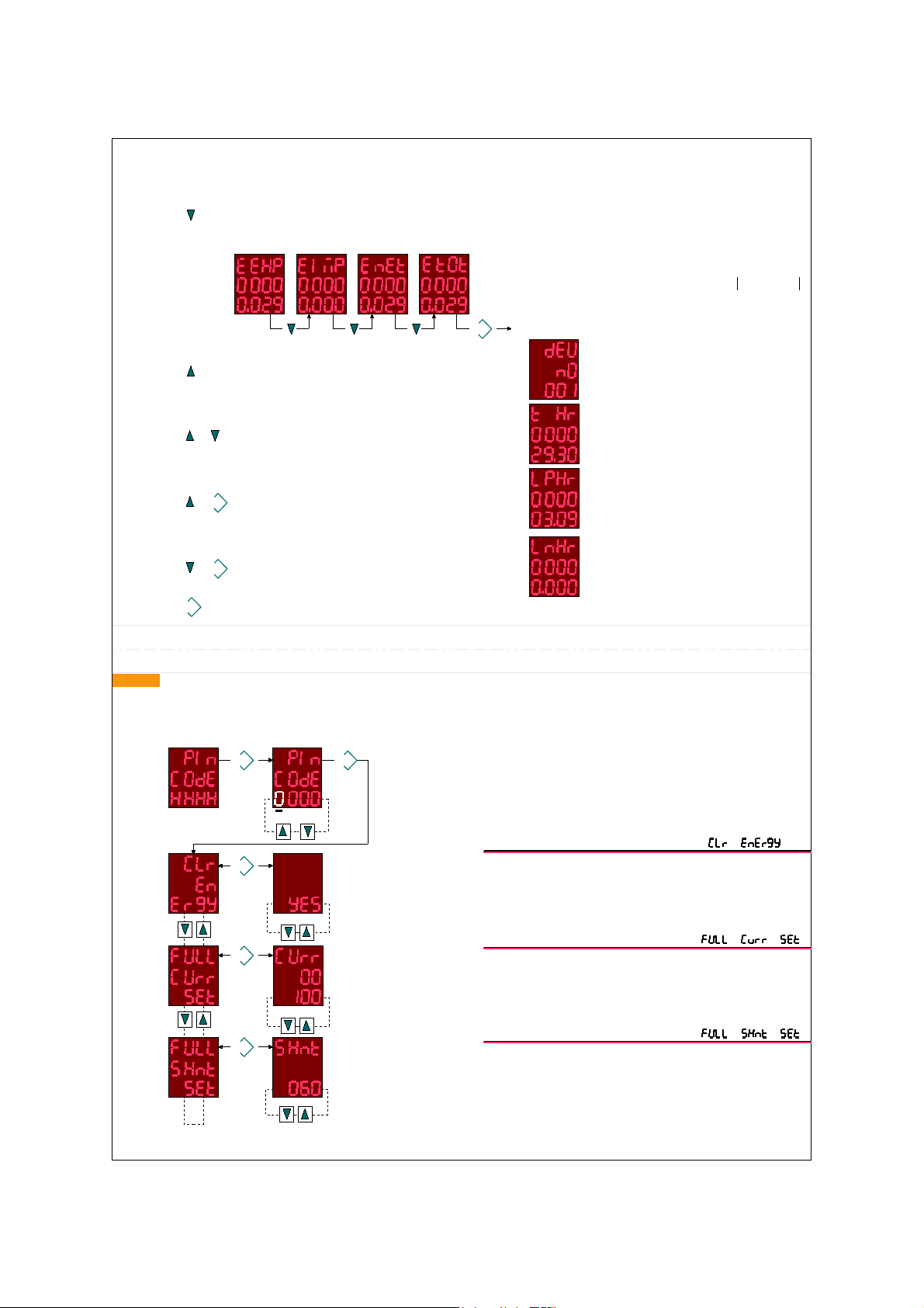
Secondary value of the shunt
resistance may vary between
50mV and 100mV. The relevant
value should be set from the
menu of the device.
Current and voltage inputs are
completely insulated from the system. Load
Current Connections
Measurement range for UH and
UL types 0-300 Vdc
Measurement range for OH and
OL types 0-300 Vdc
Voltage Connections:
DC-MULTISER DC-MULTISER
Connections

L / (-) N / (+)
Auxiliary Supply
Please connect 1.5 – 2.5 mm²
cables for models UL and OL.
18 – 75V dc
(+)(-)
L / (-) N / (+)
Auxiliary Supply
Please connect .5 – 2.5 mm²
cable for models UH ve OH.
(85 – 265Vac) & (100 – 300V dc)
(+)(-)
max.30Vdc
RO2
Relay Output
RO1
DC-MULTISER
Connect 1.5 – 2.5 mm² cable.
Contact current: max.3A/250Vac
or 3A/30Vdc
Com
PO
DC-MULTISER
Connect 1.5 – 2.5 mm² cable
Please make the connections
with CAT5 cables. Please
ground the cable shield.
RS485 Connections:
■
85 – 265V ac or 100 – 300V dc may be
applied for models UH and OH
■
18 – 75V dc may be applied for models OL and UL.
Auxiliary Power Supply Connections:
Relay Output Connections:
Pulse Output Connections:
AC/DC
AC/DC Power Supply
Relay
Power Supply
+
-
Digital Input Connections:
max.30Vdc
Com DI2
Connect 1.5 – 2.5 mm² cable.
Power
Supply
-
+
Optical
Insulation
Optik
izolasyon
DI1
Optical
insulation
Analogue output Connections:
DC-MULTISER DC-MULTISER
DC-MULTISER
■
DC-MULTISER has programmable analogue
output.
■
The output is optically insulated.
■
It may be set as 0 - 20mA or 4 - 20mA when it is intended to be used
as analogue current output.
■
It may be set as 0 -10V, 2 - 10V,
0 – 5V or 1 - 5V when it is intended to be used as
analogue voltage output
B
RS485
System
GND
RS485
Transformer
A
B
A
DC-MULTISER
AO2(+)
DC-MULTISER
Please connect 1.5 – 2.5 mm² cable.
AO(-)
Optical insulation
Gnd
ANALOGUE INPUT
for PLC or measurement
device
Load
for mA output: max load resistance >500
for V output: max load current 20mA
CAT 5
cable
ANALOGUE ......

MEASURED ELECTRICAL PARAMETERS
(dc current, dc voltage, dc power, dc energy )
able to perform measurements in kV, A, kA, W, kW, MW, GW, kWh, MWh, GWh units
SHORTCUT KEY PROPERTIES
Allows entry to energy display unit. By presing ▼ key export, import, net (difference) and total energy values may be accessed.
Returns to main screen by pressing SET key.
+
:
: device number is displayed for 3 sec. in models with RS485 properties
: operation time of the device is displayed for 3 sec
+ SET : operation duration of the device with positive current is displayed for 3 sec
+ SET : operation duration of the device with negative current is displayed for 3 sec
If Latch function is selected in models with alarm properties, alarm should be absolutely deleted by pressing
set key.If pressed for 3 sec. It goes to parameter and settings menu.
SET :
Export energy Import energy Net energy Total energy Export enegy = Positive Energy
Import enegy = Negative Energy
Net energy = (Positive Energy) - (Negative Energy)
Total energy = (Positive Energy) + (Negative Energy)
SET
Main screen
ENTRY TO PARAMETERS
If set KEY is pressed for 3 sec. password should be entered before entry to parameters menu. At this stage, HHHH is displayed in the line at the bottom of the screen while the password
screen flashes. When SET key is pressed, 0000 figures are displayed in the most bottom line and the screen begins to flash more rapidly. The flashing figures can bet set with ▼and ▲keys
and next digit can be entered by pressing SET key. When all digits are completed, if the password is correct the first parameter Clear Energy (CLR energy) section may be entered. If the
password is incorrect, the device returns to main measurement screen without entering to settings. The default value of the password is 0000. The user can change it.
SET
Blink
SET
Full scale setting of the current
(1 – 50.000A)
Shunt resistance setting
(50 – 100 mV)
YES : Clear energy
NO: Not clear energy
SET
SET
SET
Parameters
CLEAR ENERGY
CURRENT FULL SCALE SETTING
SHUNT RESISTANCE mV SETTING
This is where the line current maximum value is set. For ex: if
1000A/60mV shunt is used, then this value should be set as 1000 A.
This is the section where shunt resistance mV value can be set.
For ex: if 1000A/60mV shunt is used, then this value should be set
as 60 mV yapılmalıdır.
This is where all energies can be cleared.
In this case, pulses that are to be transmitted in the pulse output are
also cleared.
Note : Energies are reset when factory settings are enabled.

Voltage full scale setting
In UH and UL models (5 – 60 – 300V)
and OH and OL models (600 – 1000V)
SET
This is where the 4-digit password can be changed. When SET key is pressed,
0000 figure is displayed in the bottommost line and the screen begins to flash
more rapidly. The figure in the flashing digit may be set with ▼ and ▲ keys and
SET key is pressed to pass to the next digit. When all digits are completed the
new password becomes ready to use.
SET
This function enables to return to factory settings. When SET key is
pressed, Fab Set Wait (wait) is displayed and Fab Set Ok is displayed
when all settings are restored to factory settings.
SET
SET SET
SET
SET
SET
Parity : no , even , odd
Stop Bits : May be set as (1) , (1.5)
or (2).
Baud rate: It may be set as 2400,4800, 9600,19200,28800, 38400,57600 or
115200.
Device No : 001 .....255
SET
SET SET
SET
Relay Contact Position :
nO (normally switched on)
nC (normaly switched off)
Remote Access Permit
on : Access enabled
oFF : Access disabled
NOTE: When Remote Access is (on) other parameters in the menu
becomes inaccessible and previously set parameters become
disabled. This relay output may only be used via remote access.
ALARM RELAY SETTINGS
MODBUS RTU SETTINGS
RETURN TO FACTORY SETTINGS
PASSWORD SETTINGS
VOLTAGE FULL SCALE SETTINGS
It should be defined according to the maximum value by which
measurement is to be made. It may be set as (5 – 60 – 300V) in UH and UL
models and (600 – 1000V) in OH and OL models. For ex: if 30 Vdc will be
measured as maximum in the system then this value may be set as 60 V

SET SET
SET
SET
SET
SET
SET
SET
SET
SET
SET
SET
Over Voltage Set Value ( Volt Over Val):
It can bet set between 0.1 and 300 in UH and UL models.
It can be set between 0.1 and 1200 V in OH and OL
models.
Over Voltage Alarm Permit (Volt
Over EnbL) : YES ; alarm mode
enabled
NO ; alarm mode disabled
Over Voltage Alarm Mod setting (Volt Over tYPE) :
Over Voltage Delay Time (Volt Over dELy) :
It may be set between 1 – 300 sec. If the measured voltage
exceeds the set voltage value, the relay contact is released
at the end of the delay time.
Over Voltage Mistake Repair Time (Volt Over dLy0) :
It may be set between 1 – 300 sec.
Over Voltage Hysteresis Value (Volt Over
HySt): May bet set between % (1 – 30)
Exit from Over
Voltage settings
Alarm mode: when alarm is set alarm relay is pulled. When
alarm is disabled alarm relay releases.
Latch mode: when alarm mode is set alarm relay is pulled.
Alarm relay remains pulled even the alarm is disabled. If latch
mode iset in models with alarm function, alarm should be certainly
disabled by pressing the set key.
Momentary mode: In this mode, as an extra
the time seen in the adjacent box is displayed .
It may bet set between 300 msn and 5000msn.
When alarm is set, alarm relay remains pulled
until the end of this time then it is released.
This function may be used when continuous
alarm is not intended.
Low Voltage Set Value (Volt Undr Val):
It may be set between 0.1 and 300 V in UH and UL
models. It may be set between 0.1 and 1200 V in OH and
OL Models.
Low Voltage Alarm Permit (Volt Undr
EnbL)
YES ; alarm mode enabled
NO ; alarm mode disabled
Low Voltage Alarm Mode setting (Volt Undr tyPE) :
Alarm mode: when alarm is set alarm relay is pulled. When
alarm is disabled alarm relay releases.
Latch mode: when alarm mode is set alarm relay is pulled. Alarm
relay remains pulled even the alarm is disabled. If latch mode iset
in models with alarm function, alarm should be certainly disabled
by pressing the set key.
Momentary mode: In this mode, as an extra
the time seen in the adjacent box is displayed .
It may bet set between 300 msn and 5000msn.
When alarm is set, alarm relay remains pulled
until the end of this time then it is released.
This function may be used when continuous
alarm is not intended.
LOW VOLTAGE SETTINGS
OVER VOLTAGE SETTINGS

SET
SET
SET
SET
SET SET
SET
SET
SET
SET
SET
SET
Low Voltage Delay Time (Volt Undr dELy) :
It may be set between 1 – 300 sec. If the measured voltage
falls below the set voltage value, the relay contact is
released at the end of the delay time.
Low Voltage Mistake Repair Time (Volt Undr dLy0) : It
may be set between 1 – 300 sec
Low Voltage Hysteresis value (Volt Undr
HySt) :It may be set between % (1 – 30).
Düşük Gerilim Ayarlarından
ÇIKIŞ
Over Current Set value ( Curr Over Val):
It may bet set between (max. 50.000A) 0,1 and 50,000 A
depending on the maximum value of shunt resistance.
For ex: It may be set as max. 100A for 100A/60mV shunt.
Over Current Alarm Permit (Curr Over
EnbL) : YES ; alarm mode enabled
NO; alarm mode disabled
Over Current Alarm Mode setting (Curr Over tYPE) :
Over Current Delay Time (Curr Over dELy) :
It may be set between 1 – 300 sec. If the measured voltage
exceeds the set voltage value, the relay contact is released
at the end of the delay time.
Over Current Mistake Repair Time (Curr Over
dLy0) : It may be set between 1 – 300 sec.
Over Current Hysteresis Value (Curr Over
HySt) : It may bet set between % (1 – 30) .
Aşırı Akım Ayarlarından
ÇIKIŞ
Alarm mode: when alarm is set alarm relay is pulled. When
alarm is disabled alarm relay releases.
Latch mode: when alarm mode is set alarm relay is pulled. Alarm
relay remains pulled even the alarm is disabled. If latch mode iset
in models with alarm function, alarm should be certainly disabled
by pressing the set key.
Momentary mode: In this mode, as an extra
the time seen in the adjacent box is displayed .
It may bet set between 300 msn and 5000msn.
When alarm is set, alarm relay remains pulled
until the end of this time then it is released.
This function may be used when continuous
alarm is not intended.
OVER CURRENT SETTINGSI

SET SET
SET
SET
SET
SET
SET
SET
SET SET
SET
SET
LOW CURRENT SETTINGS
LOW POWER SETTINGS
Low Current Set Value (Curr Undr Val):
It may bet set between (max. 50.000A) 0,1 and 50,000 A
depending on the maximum value of shunt resistance.
For ex: It may be set as max. 100A for 100A/60mV shunt.
Low Current Alarm Permit (Curr Undr EnbL) :
YES ; alarm mode enabled
NO; alarm mode disabled
Low Current Alarm Mode Setting (Curr Undr tyPE) :
Alarm mode: when alarm is set alarm relay is pulled. When
alarm is disabled alarm relay releases.
Latch mode: when alarm mode is set alarm relay is pulled.
Alarm relay remains pulled even the alarm is disabled. If latch
mode iset in models with alarm function, alarm should be
certainly disabled by pressing the set key.
Momentary mode: In this mode, as an extra
the time seen in the adjacent box is displayed .
It may bet set between 300 msn and 5000msn.
When alarm is set, alarm relay remains pulled
until the end of this time then it is released.
This function may be used when continuous
alarm is not intended.
Low Current Delay Time (Curr Undr dELy) :
It may be set between 1 – 300 sec. If the measured current
falls below set current value, relay contact is released at the
end of the delay time.
Low Current Mistake Repair Time (Curr Undr dLy0) :
It may be set between 1 – 300 sec.
Low Current Hysteresis Value (Curr Undr
HySt) : It may be set between % (1 – 30).
Exit from Low Current
Settings
Over Power Set Value ( Povr Over Val):
It may be set as the power value at which the relay should be
released when over power is supplied.
Over Power Alarm Permit (Povr Over
EnbL) : YES ; alarm mode enabled
NO ; alarm mode disabled
Over Power Alarm Mode Setting (Povr Over tYPE) :
Alarm mode: when alarm is set alarm relay is pulled. When
alarm is disabled alarm relay releases.
Latch mode: when alarm mode is set alarm relay is pulled.
Alarm relay remains pulled even the alarm is disabled. If latch
mode iset in models with alarm function, alarm should be
certainly disabled by pressing the set key.
Momentary mode: In this mode, as an extra
the time seen in the adjacent box is displayed .
It may bet set between 300 msn and 5000msn.
When alarm is set, alarm relay remains pulled
until the end of this time then it is released.
This function may be used when continuous
alarm is not intended.

SET
SET
SET
SET
SET SET
SET
SET
SET
SET
SET
SET
LOW POWER SETTINGS
Over Power Delay Time (Povr Over dELy) :
It may be set between 1 – 300 sec. If the measured power
exceeds the set power value than the relay contact is
released at the end of the delay time.
Over Power Mistake Repair Time (Povr Over dLy0) : It
may be set between 1 – 300 sec.
Over Power Hysteresis Value (Povr Over
HySt) : It may be set between % (1 – 30)
Low Power Set Value (Povr Undr Val):
It may be set to the value where the relay should be
released when low power is supplied.
Low Power Alarm Permit (Povr Undr
EnbL) : YES ; alarm mode enabled
NO; alarm mode disabled
Low Power Alarm Mode Setting (Povr Undr tyPE) :
Alarm mode: when alarm is set alarm relay is pulled. When
alarm is disabled alarm relay releases.
Latch mode: when alarm mode is set alarm relay is pulled.
Alarm relay remains pulled even the alarm is disabled. If latch
mode iset in models with alarm function, alarm should be
certainly disabled by pressing the set key.
Momentary mode: In this mode, as an extra
the time seen in the adjacent box is displayed .
It may bet set between 300 msn and 5000msn.
When alarm is set, alarm relay remains pulled
until the end of this time then it is released.
This function may be used when continuous
alarm is not intended.
Low Power Delay Time (Povr Undr dELy) :
It may be set between 1-300 sec. If the measured power
falls below the set power value, relay contact is released at
the end of the delay time.
Low Power Mistake Repair Time (Povr Undr dLy0) : It
may be set between 1 – 300 sec
Low Power Hysteresis Value (Povr Undr
HySt) : It may be set between % (1 – 30)
Exit from Low Power
Settings
Exit from Over
Settings

SET SET
SET
SET SET
SET
SET
SET
SET
SET
SET
SET
PULSE OUTPUT SETTINGS
ANALOGUE OUTPUT SETTINGS
Analogue output enabled
Analogue output disabled
Analogue Output Permit
Pulse Types
Pulse output disabled
Total energy
Export Energy
Import Energy
Analogue Parameters
Voltage (V)
Current (A)
Power (W)
Voltage output type
V
V
V
V
Current output type
mA
mA
The device allows the below
parameters be set as analogue output.
t (msn)
t (msn)
Ps
Energy
5 – 24V
Max 30V
PuLS timE : Pulse time (Ps)
It may be set between 50msn – 900 msn .
Pulse OFF Time (Po) is fixed at 1000 msn.
dEAL : 1 pulse equivalent energy
It may bet set between 0,1kWh – 1kWh – 10kWh – 100kWh –
10000kWh – 50000kWh
Operation Range Setting
In this mode operation is carried out disregarding the symbol of
the measured value
In this mode, measred value may be set between (+) % 100 .......
This menu is displayed when PErC is selected in the Analogue measurement
range(An rAng). This screen does not appear in other modes
In this mode, output may be given at any value between (+) % 100 ....... (-) % 100
for measured value
Ps Ps
dEAL
dEAL
dEAL
1000ms 1000ms
(%) Upper Limit
(%) Lower Limit
Exit from parameter
programming menu
(-) % 100 and output is given accordingly. This will be described in
details in the following menu below.
In this mode output is given only for the measured values between
(+) % 100 - (-) % 100. This mode is the same as the operation
mode when (PerC) mode is set with the widest limits.
NOTE1 : (%) Upper Limit Value should be greater than (%) Lower Limit Value
(%) Upper Limit Value cannot be set as % 0.
NOTE2 : When measured value is outside the (%) lower limit value, Analogue
output will be V/1V or 0mA/4mA. Analogue output may be max. 6V, 12V,
24mA.

For 0 - 20mA I(analogue) =
(Measured Value)
4 +
x 100% - Lower Limit (%)
Upper Limit (%) - Lower Limit (%)
For 4 - 20mA I(analogue) =
(Measured Value)
x 100% - Lower Limit (%)
Upper Limit (%) - Lower Limit (%)
x 20mA
x 16mA
For 0 - 5 V V(analogue) =
(Measured Value)
x 100% - Lower Limit (%)
Upper Limit (%) - Lower Limit (%)
x 5 V
For 1 - 5 V V(analogue) =
(Measured Value)
x 100% - Lower Limit (%)
Upper Limit (%) - Lower Limit (%)
x 4 V
1 +
For 0 - 10 V V(analogue) =
(Measured Value)
x 100% - Lower Limit (%)
Upper Limit (%) - Lower Limit (%)
x 10 V
For 2 - 10 V V(analogue) =
(Measured Value)
x 100% - Lower Limit (%)
Upper Limit (%) - Lower Limit (%)
x 8 V
2 +
Current Outputs
Voltage Outputs
Measurement Value Analogue output value
2,5 V 5 V
= 5 V
= Voltage
(V) ) = 0 - 10
(V)
))
= =
Example 1:
Voltage Full Scale Setting
(Analogue Parameters)
(Voltage Output Type
(Analogue Operation range
setting
(PERC)
PERC
( upper limit % ) = 100 %
( lower limit % ) = 0 %
0 V 0 V
-2,5 V 0 V
Measurement Value Analogue output value
2,5 V 7,5 V
) = 5 V
) = Voltage
(V) ) = 0 - 10
(V) )) = =
Example 2:
Voltage Full Scale Setting
(Analogue Parameters)
(Voltage Output Type
(Analogue Operation range
setting
(PERC)
PERC
(upper limit % ) = 100 %
( lower limit % ) = -100 %
0 V 5 V
-2,5 V 2,5 V
for 0 - 10 V V(analogue) =
(Measured Value)
x 100% - Lower Limit (%)
x 10 V
Upper Limit (%) - Lower Limit (%)
V(analogue) =
(- 2,5 )
x 100 - (-100 )
x 10 V
100 - (-100 )
( 5 ) = +2,5V
(Full Scale Value )
(Full Scale Value )
(Full Scale Value )
(Full Scale Value )
(Full Scale Value )
(Full Scale Value )
(Full Scale Value )

= 15,73mA
Measurement Value Analogue Output Value
300 V 20 mA
) = 300 V
) = Current
(A) ) = 4 - 20
(mA) )) = =
Example 2:
Voltage Full Scale Setting
(Analogue Parameters)
(Current Output Type
(Analogue Operation range
setting
(PERC)
PERC (upper limit % ) = 100 %
( lower limit % ) = 0 %
220 V 15.72mA
0 V 4 mA
4 +
For 4 - 20mA I(analogue) =
(Measured Value)
x 100% - Lower Limit (%)
x 16mA
(Full Scale Value )
4 +
For 4 - 20mA I(analogue) =
Upper Limit (%) - Lower Limit (%)
( 220 )
x 100 - 0
100 - 0
x 16
( 300 )
Factory Set Values
MOD US RTU
Current Full Scale Setting : 100A
Shunt Resistance mV Setting : 60mV
Voltage Full Scale Setting : 300V /
1000V Password setting: 0000
Baud Rate : 9600
Stop Bits : 1
Parity : no
Device No : 1
: 300V / 1000V
: no (disables)
: alarm mode
: 10 sec
: 10 sec
: 30%
: 150V / 500V
: no (disabled)
: alarm mode
: 10 sec
: 10 sec
Over Voltage Set Value ( Volt Over Val)
Over Voltage Alarm Permit (Volt Over EnbL)
Over Voltage Alarm Mode Setting (Volt Over tYPE)
Over Voltage Delay Time (Volt Over dELy)
Over Voltage Mistake Repair Time (Volt Over dLy0)
Over Voltage Hysteresis Value (Volt Over HySt)
Low Voltage Set Value (Volt Undr Val)
Low Voltage Alarm Permit (Volt Undr EnbL)
Low Voltage Alarm Mode Setting (Volt Undr tyPE)
Low Voltage Delay Time (Volt Undr dELy)
Low Voltage Mistake Repair Time (Volt Undr dLy0)
Low Voltage Hysteresis Value (Volt Undr HySt)
: 30 %
: 100A
: no (disabled)
: alarm mode
: 10 sec
: 50A
: no (disabled)
: alarm mode
: 10 sec
: 10 sec
Over Current Set Value ( Curr Over Val)
Over Current Alarm Permit (Curr Over EnbL)
Over Current Alarm Mode Setting (Curr Over tYPE)
Over Current Delay Time (Curr Over dELy)
Over Current Mistake Repair Time (Curr Over dLy0) : 10 sec
Over Current Hysteresis Value (Curr Over HySt) : 30 %
Low Current Set Value (Curr Undr Val)
Low Current Alarm Permit (Curr Undr EnbL)
Low Current Alarm Mode Setting (Curr Undr tyPE)
Low Current Delay Time (Curr Undr dELy)
Low Current Mistake Repair Time (Curr Undr dLy0)
Low Current Hysteresis Value (Curr Undr HySt)
: 30 %
: 30.000VA / 100.000VA
: no (disabled)
: alarm mode
: 10 sec
: 10 sec
: 30 %
: 15.000VA / 50.000VA
: no (disabled)
: alarm mode
: 10 sec
: 10 sec
Over Power Set Value ( Povr Over Val)
Over Power Alarm Permit (Povr Over EnbL)
Over Power Alarm Mode Setting (Povr Over tYPE)
Over Power Delay Time (Povr Over dELy)
Over Power Mistake Repair Time (Povr Over dLy0)
Over Power Hysteresis Value (Povr Over HySt)
Low Power Set Value (Povr Undr Val)
Low Power Alarm Permit (Povr Undr EnbL)
Low Power Alarm Mode Setting (Povr Undr tyPE)
Low Power Delay Time (Povr Undr dELy)
Low Power Mistake Repair Time (Povr Undr dLy0)
Low Power Hysteresis Value (Povr Undr HySt)
: 30 %
RELAY CONTACT POSITION : nO (normally ON)
Remote Access Permit : oFF (Access disabled)
Pulse Type: OFF
Deal : 1kWh
Pulse Time: 100ms
Analogue Output Permit
Parameter
Output type
Operation Range Setting
PERC % upper limit
PERC % lower limit
:no (disabled)
:VOLT (voltage measurement):
0 – 10 V
: PERC
: +100%
: 0%
ANALOG OUTPUT PULSE OUTPUT RELAY OUTPUT
ALARM SET VALUES

Technical Information
1.
Measurements
Parameter Measurement Range Description
Voltage
Accuracy
0,5 %
0 ~ (±) 5 V
0,1 %0 ~ (±) 60 V
0,1 %0 ~ (±) 300 V
Current
0,1 %
0 ~ (±) 50.000 A
0,5 %
0 ~ (±) 600 V
0,5 %0 ~ (±) 1000 V
For 50 mV and 100mV Shunt Output
Power
0,5 %0 ~ (±) 60.000 kW
Energy
0,5 %0 ~ (±) 99.999.999,99 kWh
2.
Measurement Inputs
Parameter Description
DC Voltage
300 KΩ DC-MULTISER-1UH-DIN , DC-MULTISER-1UL-DIN , DC-MULTISER-2UH-DIN , DC-MULTISER-2UL-DIN
2,5 MΩ
15 KΩ
May be used with shunt. Can be progrramed between 0 ~ (±) 50.000 A/ 50 – 100mV
DC Current
Input impedence
Operation Voltage
: 5 – 24Vdc max. 30Vdc
3.
Digital Input (1 pc)
4.
Relay Output (1 pc)
Operation Voltage
Max Load Voltage
Max Load Current
: 1NO and max.5A/250
Vac : 250 Vac/30Vdc
: 5A
5.
Analogue Output (1 pc)
Voltage Output Type
Current Output Type
Accuracy
Load Capacity
: 0-10V, 2-10V, 0-5V, 1-5V
: 0-20mA, 4-20mA
: 0.2%
: In current type, max. load resistance
750 Ohm
: In voltage type, load current max. 20
mA
Updating Duration: 200ms
6. RS485
Type
Protocol
Baud rate
Stop Bits
Parity
: Half dublex
: Modbus RTU
: 2400,4800,9600,19200,28800,38400,57600 or 115200 :
(0.5) , (1) , (1.5) or (2)
: no , even , odd
Device No
: 1 .....255
7.
Operation Voltage
(DC-MULTISER-1UH-DIN, DC-MULTISER-1OH-DIN, DC-MULTISER-2UH-DIN, DC-MULTISER-2OH-DIN)
(DC-MULTISER-1UL-DIN, DC-MULTISER-1OL-DIN, DC-MULTISER-2UL-DIN, DC-MULTISER-2OL-DIN)
Operation Voltage(Un): 85 – 265 Vac or 100 – 300 Vdc
Operation Voltage (Un): 18 – 75 Vdc
Operation Frequency: 50/60 Hz
DC-MULTISER-1OH-DIN , DC-MULTISER-1OL-DIN , DC-MULTISER-2OH-DIN , DC-MULTISER-2OL-DIN
Device Protection Class : IP 20
Terminal protection class : IP 00
Ambient Temperature
: - 5 °C .... + 50 °C
: to automat rail
Conneciton Type
Dimensions
: 105x90x59 mm
8.
Environment
105 mm 59 mm
34 mm
90 mm
This manual suits for next models
7
Table of contents
Other KAEL Multimeter manuals
Popular Multimeter manuals by other brands

KYORITSU
KYORITSU KEW MATE 2000A instruction manual

GW Instek
GW Instek GDM-8251 user manual

Gossen MetraWatt
Gossen MetraWatt METRAport 32 XS operating instructions

NI
NI PXIe-4081 Calibration guide

Keysight Technologies
Keysight Technologies U1251B quick start guide

Chauvin Arnoux
Chauvin Arnoux C.A 6550 user manual