Kaishan KRSD Series User manual

PN: 96002015000010
Release 2016, Version: A
KRSD Series
Rotary Screw
Air
Compressor
Instruction
Manual
(Controller MAM-6090)

KRSD series Page 2
TABLE OF CONTENTS
1. Safety Information…………………...………………………………………………4
1.1 Safety Alert Symbols………………………………………………………………4
1.2 Safety Precautions………………………………………………...………………...5
1.3 Pressure……………………………………..……………………………………….5
1.4 Fire and Explosion…………………………..……………………………………...6
1.5 Moving Parts………………………………………………..………………………6
1.6 Hot Surfaces…………………………….………………………….……………….6
1.7 Proper Compressed Air Applications......................................................6
1.8 Electrical Shock……………………………………………….…………………….7
2. General Information……………………………………………………………………8
2.1 Introduction…………………………………………………………………………8
2.2 The Compression Cycle…………………………………………………………….9
2.3 Compressor Lubrication and Cooling System…………………………..……...10
2.4
Compressor Discharge System…………………………………….……………..10
2.5 Air-end, Inlet Valve and Filtration System…………………………………….11
3. Fluid Information……………………………………………………………………..12
3.1 Fluid Guide………………………………………………………………….……..12
3.2 Fluid Change and Recommendations……………………………………....……13
4. Installation……………………………………………………………………………..14
4.1 Compressor Mounting, Support and Location…………………………………14
4.2 Ventilation and Cooling……………………………………….…………………14
4.3 Piping Connection………………………………………………………..............15
4.4 Fluid Level Inspection………………………………………….…………………16
4.5 Electrical………………………………………..…………………………………17
4.6 Motor Rotation Inspection…………………………………………...…………...17
4.7 Fan Rotation Inspection …………………………………………….……………18
5. Operation…………………………………………………………………….………...19
5.1 Routine Operation…………………………………………….…………………..19
5.2 Electronic controller basic operation…………………………………………20
5.3 Program structure…………………..…………………………… ………………23

Page 3KRSD series
5.4 Technical parameters….…………………………………………………………41
5.5 Alarms………..…………………………………………………………………43
6. Servicing………………………………………………………………………………..44
6.1 Fluid Change……………………………………………………………..……..44
6.2 Air Filter……………………………………………………………………….…..44
6.3 Fluid Filter………………………………………………………………………....45
6.4 Air/Oil Separator………………………………………………………………….45
6.5 Fluid sampling procedure……………………………………………………….45
6.6 Maintenance Schedule…………………………………………………………….46
7. Troubleshooting Guide.………………………………………………………………48
8. Standard Terms and Conditions ……………………………………………….…..51

KRSD series Page 4
Safety Information
Thank you for choosing Kaishan Compressor. Please read this instruction manual carefully
before using the compressor. This manual must be kept in the safe place for future
reference. Kaishan Compressor’s authorized distributors provide maintenance service for
KRSD series rotary screw compressors. A certified technician is required to ensure
compressors maintenance is safely handled. By following the instructions in this manual,
the user will minimize possibility of an accident throughout the useful life of this
equipment.
1.1 SAFETY ALERT SYMBOLS
Key hazards are used throughout this manual. The level of hazards seriousness is
symbolized as follows:
This symbol identifies immediate
hazards which will result in severe
personal injury, death or substantial
properly damage.
This symbol identifies hazards or
unsafe practices which could
result in personal injury, death or
substantial property damage.
This symbol identifies immediate
electrical hazards which will result
in severe personal injury, death or
substantial properly damage.
This symbol identifies hazards or
unsafe practices which could
result in personal injury or
substantial property damage.
This symbol identifies immediate
hot surface hazards which will
result in severe personal injury.
NOTICE
Identifies important installation,
operation or maintenance
information which is not hazard
related.
1.2 SAFETY PRECAUTIONS

Page 5KRSD series
This manual describes the safety precautions, structure, and functions of all systems and
components, as well as the operation and maintenance methods for the KRSD series rotary
screw air compressors. The owner and operator shall read the manual carefully. Only after
thorough understanding should the machine be operated for the first time. This manual
gives you a general description of the mechanical and electrical systems and maintenance.
However, if you have any questions about operating and maintenance of the compressor,
please contact your authorized distributor or our service department personnel.
Do not modify the compressor and/or controls in any way except with written factory
approval. While not specifically applicable to all types of compressors with all types of
prime movers, most of the precautionary statements contained herein are applicable to most
compressors and the concepts behind these statements are generally applicable to all
compressors.
Failure to follow any of these precautions may results in severe personal injury,
death, property damage and/or compressor damage
1.3 PRESSURE
A properly sized pressure relief valve must be installed in the discharge piping ahead
(upstream) of any shutoff valve (block valve), heat exchanger, orifice, or any potential
blockage point. Failure to install a pressure relief valve could result in the rupturing or
explosion of some system components. Relieve all pressure internally to the compressor
prior to servicing. Do not depend on check valves to hold system pressure. Do not change
the pressure setting of the pressure relief valve, restrict the function of the pressure relief
valve, or replace the pressure relief valve with a plug. Over pressurization of system or
compressor components can occur resulting in death, severe personal injury, or property
damage. Do not operate the compressor at pressures in excess of its rating. Never use
plastic pipe, rubber hose, or soldered joints in any part of the compressed air system.
Failure to ensure system compatibility with compressor piping is dangerous
1.4 FIRE AND EXPLOSION

KRSD series Page 6
Clean up any spills of lubricant or combustible liquid immediately. Keep sparks and flame
away from the compressor. Do not permit smoking during servicing, such as checking or
adding fluid. Wipe down spills immediately using industrial cleaner as required. Do not use
flammable material for cleaning purposes. Do not operate the compressor in a hazardous
environment unless the compressor has been specially designed for that environment. Wear
personal protective equipment including safety goggles and clothing during servicing the
compressor. Never use a flammable or toxic solvent for cleaning the air filter or any parts.
1.5 MOVING PARTS
Keep hands, arms and cloths away from the coupling and fans of the compressor. Do not
remove any guards or cabinet panels or attempt to service any compressor part while the
compressor is operating.
1.6 HOT SURFACES
Do not touch any hot surface and parts during the compressor’s operation. Keep all body
parts away from air/oil receiver tank, steel tubing, air end and after-cooler. Wear personal
protective equipment including gloves while servicing the compressor.
1.7 PROPER COMPRESSED AIR APPLICATIONS
Air from this compressor will cause severe injury or death if used for breathing or food
processing. Air used for those processes must meet OSHA and applicable industry
regulations. This compressor is designed for use in the compression of normal atmospheric
air only. No other gases, vapors or fumes should be exposed to the compressor intake, nor
processed through the compressor. Keep personnel away from the compressed air discharge.
Use compressed air for cleaning purpose only with effective chip guarding and personal
protective equipment which meet OSHA standard and/or any federal, state, local codes,
standard and regulation.
1.8 ELECTRICAL SHOCK

Page 7KRSD series
Never start the compressor unless it is safe to do so. Do not attempt to operate the
compressor with a known unsafe condition. Tag the compressor and render it inoperative
by disconnecting and locking out all power at the source or otherwise disabling its prime
mover so others who may not know of the unsafe condition cannot attempt to operate it
until the condition is corrected. Install, use and operate the compressor only in full
compliance with all pertinent OSHA regulations and/or any applicable Federal, State, and
Local codes, standards and regulations. Never assume it is safe to work on the compressor
because it is not operating. Many installations have automatic start/stop controls and the
compressor may start at any time.
NOTICE
- Follow all maintenance procedures and check all safety devices on schedule.
- Use the correct compressor fluid at all time
- Do not rely on the discharge check valve to isolate the compressed air service line
- Keep panels closed at all times, and stay away from hot surfaces to prevent
hazards
NOTICE
These instructions, precautions and descriptions cover KRSD series air
compressors. As a service to our customers, we often modify or construct packages
to the customer’s specifications. This manual may not be appropriate in those cases.
Every effort has been taken to ensure complete and correct instructions have been included
in this manual. However, possible product updates and changes may have occurred since
printing this manual. Kaishan Compressor USA reserves the right to change specifications
without incurring any obligation for equipment previously or subsequently sold.

KRSD series Page 8
General Information
2.1 INTRODUCTION
The KRSD series offer models with power ranging from 30 hp to 50 hp. These direct
driven compressors have standard full load pressure rating from 100 psi to 175 psi (7 bar to
13 bar). The compressor is a single stage, positive displacement, fluid-flooded rotary screw.
A complete package consists of following:
Compressor (Air End)
Electric motor
Starter
Air Inlet System
Compressed air Discharge System
Lubrication and Cooling System
Capacity Control System
Instrumentation Panel
Air and Fluid Cooling System
Air/ Fluid separation tank (Reservoir)
All components are assembled on a structural steel base with enclosure. The control panel
is located in the front of the enclosure door panel. Acoustical enclosure is one of the
standard features for all compressors.
NOTICE!
Dismantling the compressor’s enclosure may void its warranty.

Page 9KRSD series
2.2 THE COMPRESSION CYCLE
The compressor housing contains of two rotors; Male and
Female rotors. The male rotor has five lobes and female rotor
has six flutes. They are constantly and precisely meshed, and
housed in the cylinder with two parallel adjoining bores. All
parts are machined to exacting tolerances. The rotors provide
positive-displacement internal compression smoothly and
without surging. As the rotors rotate, air is drawn into the
cylinder through the inlet port. A volume of air is filled and
trapped as the rotor lobes pass the inlet port in the cylinders.
Compression occurs as the male rotor rolls into the female
flute, progressively reducing the space thereby raising the
pressure. Compression continues until the lobe and flute pass
the discharge port. The compressed air is then discharged into the air/oil separator tank.
There are five complete compression cycles for each complete rotation of the male rotor.
When the compressor is operating, a partial vacuum is produced at the compressor inlet.
Fluid is injected into the compressor unit and mixed with the air. The fluid has three basic
functions:
•As a coolant, it controls the rise in air temperature normally associated with the heat
of compression.
•It seals the leakage paths between the rotors and stator and also between the rotors
themselves.
•It acts as a lubricating film between the rotors allowing one rotor to directly drive
the other, which is an idler.
After air/fluid mixture is discharged from compressor to the reservoir, fluid is separated
from the air in the separator tank. Compressed air then flows through the after-cooler for
moisture removal while the lubricant is being cooled by the fluid-cooler for re-injection.

KRSD series Page 10
2.3 COMPRESSOR LUBRICATION AND COOLING SYSTEM
The lubrication and cooling system consists of a reservoir, centrifugal fan, fan motor,
aluminum finned fluid-cooler and after-cooler, thermal valve & fluid filter. High pressure
forces the lubricant through a series of direction changes in the reservoir where it is
separated from the air. The fluid is then delivered to the thermal valve and fluid-cooler.
Cooled fluid will be filtered before being re-injected back into the compressor.
Ambient air is being forced through the cooler fins by the centrifugal fan, which cools the
fluid and compressed air in the cooler tubes. The after-cooler helps separate the water
content in the discharge air, and through the automatic condensate drain, the water will be
drained. This avoids water contamination problems downstream (in service lines). Cooler
fins must be kept clean at all times.
Fluid from reservoir circulates to the thermal valve. The thermal valve is fully closed when
the fluid temperature is below 70°C (158°F). Fluid (below 158°F) will bypass the thermal
valve and inject directly to the airend. As the discharge temperature rises above 80°C
(176°F), due to heat of compression, the thermal valve begins to open and fluid will be
circulated to the cooler.
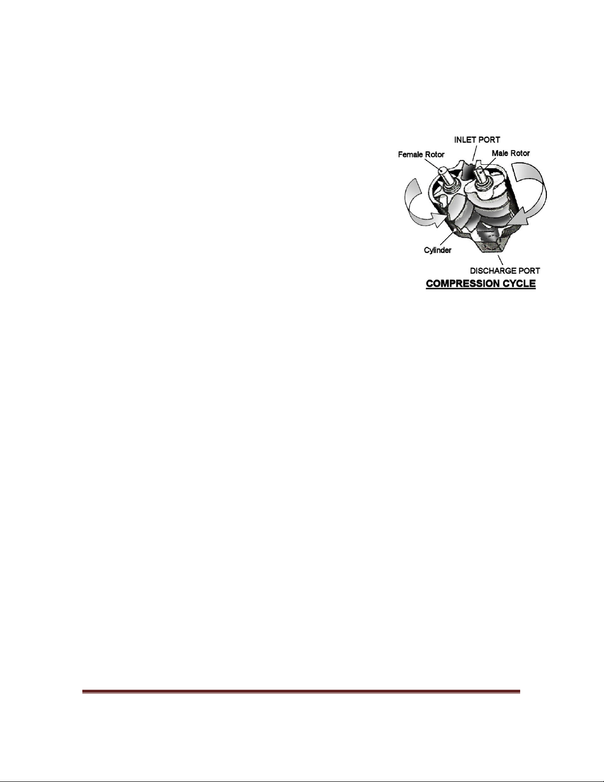
2.4 COMPRESSOR DISCHARGE SYSTEM
Air/fluid mixture has been forced into reservoir after compression. The reservoir has two
basic functions:
•It acts as a primary fluid separator.
•It serves as the compressor fluid sump.
The compressed air/fluid mixture enters the reservoir and is directed against the internal
baffle. Turbulent flow occurs, and velocity is significantly reduced, thus causing large
droplets of fluid to form and fall to the bottom of reservoir. Fluid collected in the reservoir
will then be returned to the compressor due to the pressure differential.
The sight glass enables the operator to visually monitor the reservoir fluid level. Fluid is
added to the reservoir by removing the fluid filling cap after all system pressure is relieved.
The fluid level should remain at the top red lines on the sight glass. Fluid refill is required
once its level drops below the lower red line.
The minimum pressure check valve assures the reservoir maintains a minimum pressure
between 58 psig and 72 psig (4Bar and 5Bar) during unloading conditions. This pressure is
necessary for air/fluid separation and fluid circulation.

Page 11 KRSD series
2.5 AIREND, INLETVALVE AND FILTRATION SYSTEM
The compressor inlet system consists of a air filter, inlet valve. & SKKairend. The inlet
valve controls the air intake volume. It is also acts as the check valve to prevent the reverse
pressure and rotation when compressor is shutting down.
Air end
Inlet valve
Casing for air filter

KRSD series Page 12
Fluid Information
3.1 FLUID GUIDE
KRSD compressors are filled & tested with Kaishan lubricant. Refer Figure 3-1 for filler
port, sight glass, quarter-turn valve location on the reservoir. The compressor is filled with
the manufacturer’s recommended quantity of Kaishan fluid. Inspection of the reservoir
fluid level during installation or operation is recommended.
Figure 3-1: Fluid Fill Location
Do not use different fluid. Using different fluid will void compressor’s warranty.
Air/Oil Separator Tank
Fluid Fill Port
Sight Glass
Fluid Drain Valve

Page 13 KRSD series
3.2 FLUID CHANGE RECOMMENDATIONS
LUBRICANT FLUID CHANGE FLUID FILTER
CHANGE SEPARATOR
CHANGE
KTL8000
Every 8,000 hours
or as indicated by
sampling report
Every 2,000 hours
or as indicated by
Delta P
Every 8,000 hours
(4,000 hours for
“spin on” type
separator) or as
indicated by Delta P
KTL4000 FG Every 4,000 hours
or as indicated by
sampling report
Every 2,000 hours
or as indicated by
Delta P
Every 8,000 hours
(4,000 hours for
“spin on” type
separator) or as
indicated by Delta P

KRSD series Page 14
Installation
4.1 COMPRESSOR MOUNTING, SUPPORT AND LOCATION
Compressor should be located on a flat surface in a clean, well-lit and well-ventilated area.
The location must have sufficient access for maintenance equipment and lifting vehicle.
Four feet (4’) of clearance around the compressor is recommended for daily inspection and
easy access to all compressor components. The area must have sufficient lighting for
technicians to safely operate the compressor as well as perform maintenance work. The
location should be free from standing water.
The compressor’s base must be installed on a level surface that can support the gross dead
weight of the machine. Rubber pads with 5 - 15mm thickness or pliable material should be
placed under the bottom of the base if floor surface is uneven or irregular. A stationary
compressor will prevent accidents such as broken piping or electrical connections.
NOTICE!
Brand new compressor has “Orange Color” shipping bracket installed under
airend assembly. Please remove the bracket after the unit is installed.
Removal or paint over of safety labels will be a safety hazard. This could result in
personal injury or property damage. Warning signs and labels should be conspicuous
and on a bright legible surface. Do not remove any warning, caution or instructional
material attached with unit.
4.2 VENTILATION AND COOLING
Ambient temperature should not exceed 40°C (104°F). High ambient temperatures
may result in high air temperature shutdown.

Page 15 KRSD series
NOTICE!
Do not install and operate compressor if the ambient temperature is below
2°C (35°F). Severe ambient modifications must be installed with the unit for
lower ambient temperatures.
The compressor air inlet must be located in the opposite direction to other compressors or
heat generating equipment. The object is to avoid hot air being drawn into the system. Do
not block the exhaust air from cooler or fan. Hot exhaust air must be vented outside through
a duct to prevent high ambient room temperature. The compressor room must be properly
ventilated to avoid compressor high temperature shutdown.
Maintain clean & fresh air, dust free, metal particle free and chemical vapor
free in the compressor’s room. Housing the compressor within a poorly
ventilated enclosure will cause higher operating temperature.
Under no circumstances should a compressor be installed in an area exposed to
toxic, volatile or corrosive atmosphere, nor should toxic, volatile or corrosive
agents be stored near the compressor.
All models are intended for indoor installation; however, it is possible, with certain
modifications, to accommodate some outdoor locations. Models with standard enclosure
are water-resistant but not water tight. Shelter is needed to protect the unit from rain, snow
and freezing temperatures. An optional weather hood or air grille could be installed to
protect compressor against blowing rain and snow as well as cabinet heater additions if
ambient temperature will be below 2°C (35 F).
4.3 PIPING CONNECTION
Before installation, review the complete air systems layout, which includes compressor(s),
receiver tank, dryer(s), line filter(s), pipe size, water drain and isolator valves. Never join
pipes or fittings by soldering. Never use PVC pipe or non-genuine rubber hose in the air
system. Use flexible connections to prevent pipe load from being transmitted to the
compressor. Never use a different pipe size other than the manufacturer specification for
the compressor unit.

KRSD series Page 16
A service line shut off valve must be installed after the compressor air outlet connection
with a pressure relief valve installed to release compressed air to the atmosphere. For a
single compressor and air receiver tank, manual shut off valves are typically being installed.
A union connector must be installed after the ball valve (quarter turn, shut off valve) at the
compressed air outlet. This will allow unit isolation for maintenance.
Make sure system pressure is relieved by confirming that sump pressure
gauge is reading zero prior to servicing. Failure to relieve system pressure
could result in death or serious injury and property damage.
A receiver tank should be installed if compressed air demands fluctuate. Service line piping
is recommended to be sized to match the compressor’s discharge connector. All piping &
fittings should be rated to withstand greater pressure than the discharge pressure. Isolation
valves & drain valves are installed to isolate the compressor when service is required.
These valves should have water drip legs with the drain direction facing downward to the
floor. Piping should all line up properly with an adequate loop radius or bend radius given
for easy installation and to prevent bending stress, flow restriction and damage due to
thermal expansion. Piping support brackets must be mounted independent of the
compressor and motor. This will avoid damage caused by vibration.
Pressure relief valves are sized to protect the system. Never change the pressure setting or
tamper with the valve. Only the valve manufacturer and their authorized representatives are
allowed to make such changes.
Pressure relief valves are used to protect system integrity in accordance with
safety standards. Failure to provide properly sized valves will result in death or
serious injury.
Pressure relief valves are installed prior to any potential blockage point such as shutoff
valves, heat exchangers and discharge silencers. Ideally, the valve should be threaded
directly into the pressure point it is sensing, not connected with tubing or pipe. Always
direct discharge from relief valves to a safe area away from personnel.
4.4 FLUID LEVEL INSPECTION
Inspect the fluid level when the compressor is in shut down mode. Fluid level is indicated
on the reservoir sight glass. The maximum fluid level is at the top red-mark. Add fluid until
the top red-mark is reached.

Page 17 KRSD series
4.5 ELECTRICAL
Before installation, the electrical supply should be checked for adequate wire size and
capacity. User must comply with national & local electrical codes. The codes specify the
surrounding clearance requirement for the electrical panel. Wiring work should be
undertaken only by a qualified electrician in compliance with OSHA, national or local
electrical code. KRSD compressor includes wiring diagrams for user reference. Refer to the
electrical control schematic in the parts manual for wiring diagrams. A dedicated and fused
disconnect switch or circuit breaker should be purchased for the installation. Any
unreasonable voltage imbalance (5%) between phases must be eliminated and low voltage
problems must be corrected to prevent excessive current draw. Air compressors must be
grounded in accordance with applicable codes, regulations and requirement.
Kaishan Compressor would like to emphasize the importance of providing
adequate grounding for air compressors. The common practice of grounding
units to a building’s structural steel may not provide adequate grounding
protection, as paint and corrosion build-up may exist.
All electrical supply cables must be adequately sized to prevent overheating due
to current draw.
Enclosure panels and drive grille must be fastened in place before starting the
compressor and never removed before lock out / tag out of the main power
supply.
A knock out hole is provided for an incoming power connection. If a different location for
the starter hole is needed, the certified technician must make sure to keep control box clean
after the hole is created. The original hole must be capped if another hole is used. Inspect
incoming voltage to match the compressor’s specification. Inspect motor starter and
overload heater sizes. Check electrical connections L1-L2-L3 for tightness and cleanliness.
4.6 MOTOR ROTATION INSPECTION
Motor rotation must be checked after the wiring has been installed. Operating the
compressor in incorrect rotation will result in severe damage to the compressor and
warranty coverage will be voided. Motor rotation can be viewed through the opening in the
drive grille. The drive motor end of the compressor is marked with an arrow noting the
proper rotation.

KRSD series Page 18
To inspect rotors rotation, pull out the “EMERGENCY STOP” button and press once,
quickly press the “START” and “STOP” button in sequence, allowing the motor to turn 2
or 3 revolutions. Observe the drive shaft for correct direction. If reverse rotation is observed,
disconnect the power supply, reverse power input leads at the motor starter. Recheck for
proper rotation.
4.7 FAN ROTATION INSPECTION
Fan motor rotation should be inspected. KRSD compressors use an axial fan for cooling.
Fan rotation is inspected through an arrow shaped observation hole above the fan motor.
The fan must rotate in the direction indicated by the arrow.
NOTICE!
Always inspect fan rotation through the observation hole. Never assume the fan
rotation is correct based on the induced air flow across the coolers. A centrifugal
fan can pull the airflow across the coolers when rotating in either direction;
however, incorrect rotation will cause high discharge temperature.

Page 19 KRSD series
Operation
5.1 ROUTINE OPERATION
Provisions should be made to have the instruction manual readily available to the
operator and maintenance personnel. If, for any reason, any parts of the manual
become illegible or if the manual is lost, have it replaced immediately. The
instruction manual should be read periodically to refresh one’s memory. This
may prevent a serious accident.
Before compressor start up, inspect fluid level in reservoir. After start up, observe the
control panel screen for operation status. Ensure the compressor is running at its optimum
level.
Close the service valve to plant air distribution system. Allow pressure to build up within
the reservoir until compressor fully unloads. Press the stop button.
NOTICE
Always close the service valve when compressor is not being used. It prevents
back pressure from the service line and avoids leakage due to check valve failure.
NOTICE
Emergency shutdown. Press the emergency stop button or pull the circuit breaker
at the main power terminal.

KRSD series Page 20
Operation
5.2 BASIC OPERATION
5.2.1. Screen display and basic operation
Power up screen: Boot up screen, after 5 seconds:
Normal display screen:
Icon touch screen display:
Line Pressure
Discharge Temperature
Current
Voltage
Fan Status
Compressor Status
Total Run Hours
Total Load Hours
Run Parameters
User Parameters
Factory Parameters
Calibration Set
Sequence Parameters
Configuration Parameters
Maintenance Parameters
VSD Settings
Touch Calibration
Schedule Setup
Schedule Activate
Fault History
Motor VSD
Fan VSD
Date and Time Set
Return
Other manuals for KRSD Series
1
This manual suits for next models
2
Table of contents
Other Kaishan Air Compressor manuals
Popular Air Compressor manuals by other brands

Clarke
Clarke RANGER 6/500 Operation & maintenance instructions

EINHELL
EINHELL CC-AC 35/10 12V Original operating instructions

Parkside
Parkside PKO 270 A1 Operating and safety instructions

DeWalt
DeWalt D55143 instruction manual

Jenny
Jenny Reciprocating Air Compressors Operation and maintenance manual

DeWalt
DeWalt D55250 instruction manual