DIGITAL
LIGHT METER
Instruction Manual
KG-75
To prevent an electrical shock hazard to the operator
and/or damage to the instruments, read this instruction
manual carefully before using the instrument. WARNINGS
with the symbol on the instrument and this instruction
manual are highly important.
For Safety Measurements!!
Thank you for purchasing "KG-75 DIGITAL LIGHT
METER". To obtain the maximum performance of this
instrument, read this Instruction Manual carefully, and
take safe measurement.
Introduction
Confirm if the following items are contained in the
package in good condition. If there is any damage or
missing items, ask your local dealer for replacement.
1. Unpacking And Inspections
3. Safety Precautions
4. Name Illustration
・Do not replace the battery with the wet hands.
Electric shock may occur.
Do not keep the instrument in the following place.
・The place where has the water splash
・The place where applies the hard shock
・-10℃or less, 50℃or more, 70%RH or more
・The place where has the condensation
・The place where is exposed to direct sunlight
Cautions for safekeeping
−
1
− −
2
− −
3
−
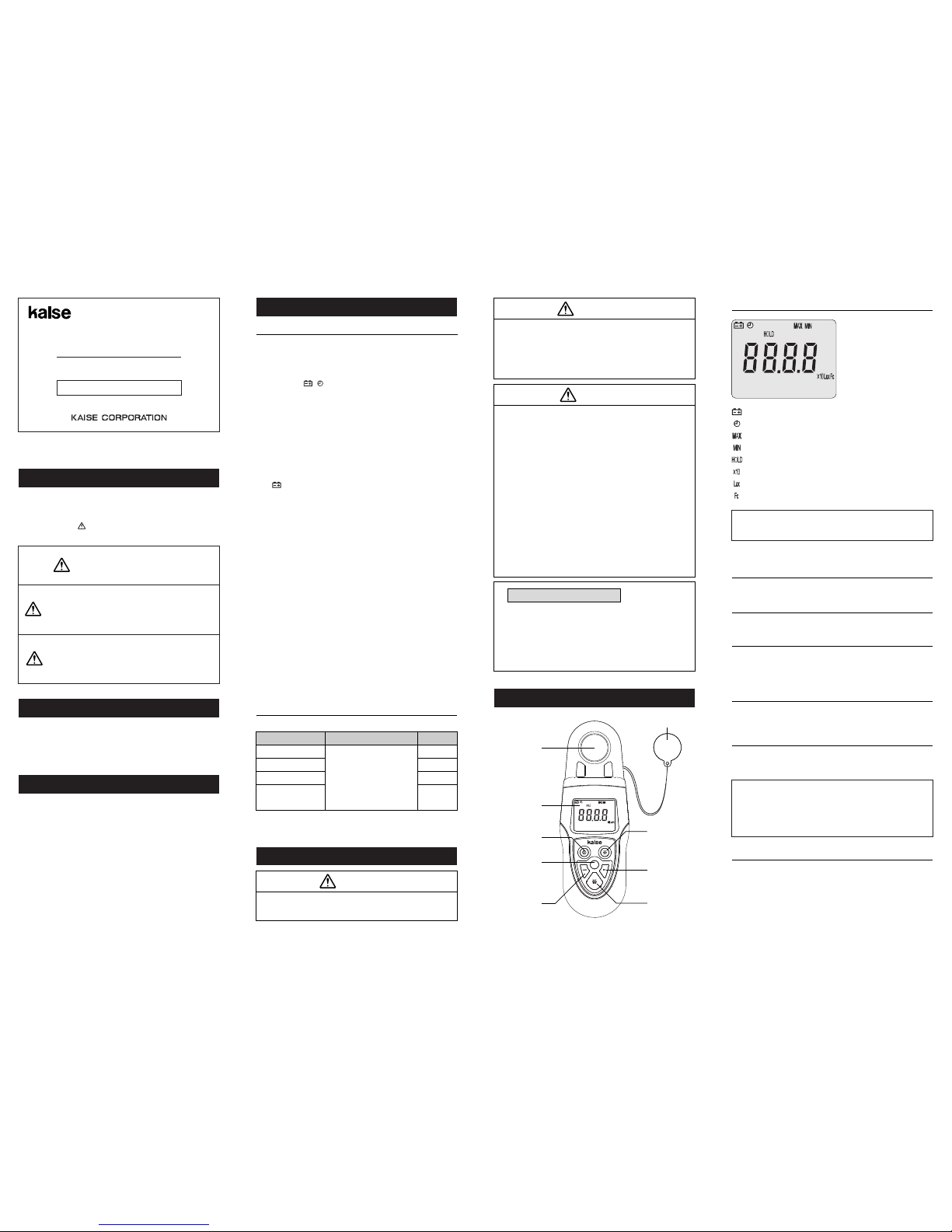
4-1. LCD
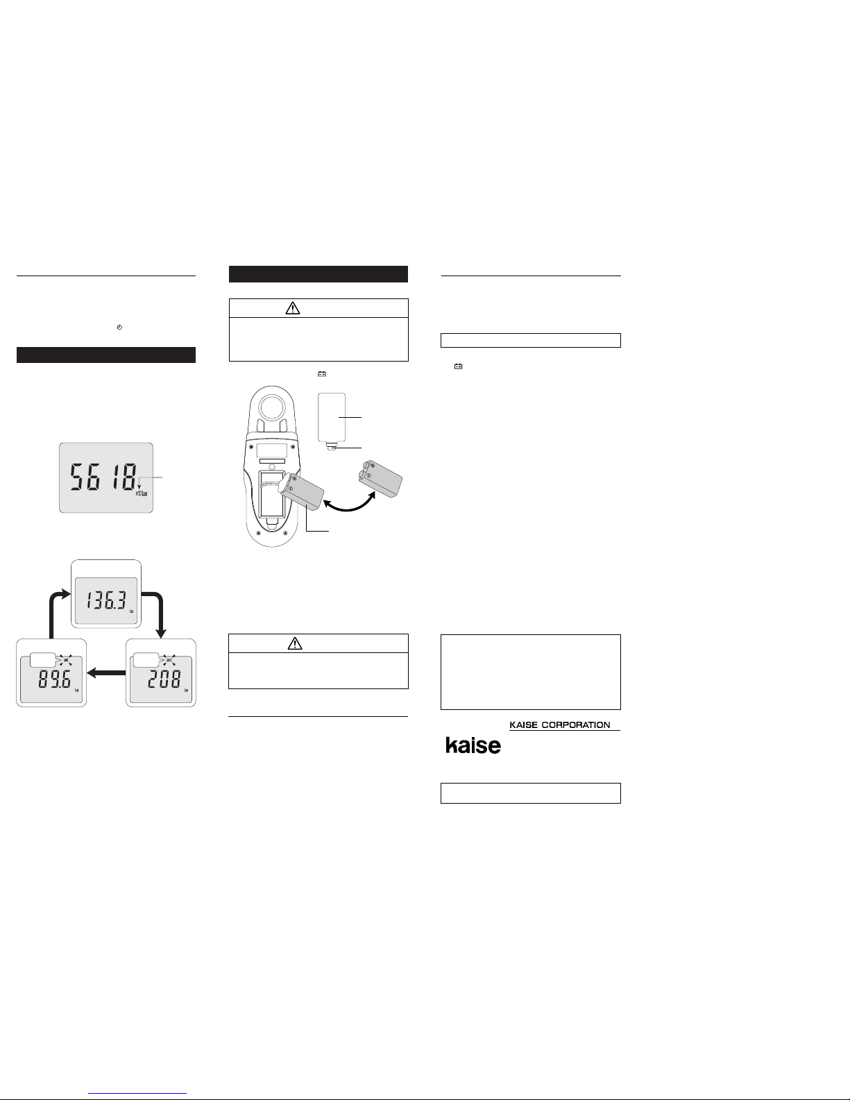
Fig-2
1. Digital Light Meter
2. 9V 6F22 Battery
3. Instruction Manual
1 pce.
1 pce.
1 pce.
LIGHT METER KG-75
HOLD
Sensor
Sensor Cap
LCD
POWER Key
MAX/MIN
Key
LIGHT Key
HOLD Key
LUX Key
FC Key
ANGLED INCIDENT LIGHT CHARACTERISTICS : not specified
TEMPERATURE COEFFICIENT : Accuracy at 23℃±5℃×0.1/℃
Range
0.00 to 19.99Lux
20.00 to 199.9Lux
200 to 9999Lux
1000 x 10 to
9999 x 10Lux
0 to 300Lux :±6%±3dgt
301 to 4000Lux : ±6%
4001 to 99990Lux : ±10%
Accuracy
Resolution
0.01Lux
0.1Lux
1Lux
10Lux
(23℃±5℃, <80%RH in non-condensing)
2-2. MEASUREMENT SPECIFICATION
2. Specifications
1.
2.
3.
4.
5.
6.
7.
8.
9.
10.
11.
12.
13.
14.
15.
16.
17.
18.
19.
20.
DISPLAY (LCD) :
a. Numerical Display : Maximum reading 9999,
11mm high
b. Units and Symbols : Lux, Fc,×10,MAX, MIN,
HOLD, ,
SENSOR : Silicon photodiode and filter
MEASURING RANGE : 0 to 99990Lux, 0 to 9999Fc
×10 sign when exceeding 9999Lux
Example : 99990Lux →display 9999 and ×10
RANGE SELECTION : Auto Ranging
OVERRANGE INDICATION : "OL" appears when the
upper limit of measuring range is exceeded
SAMPLING RATE : 2.5 times/second
BATTERY WARNING :
" " indication at approx. 6.8V or less
DISPLAY HOLD : Hold indicating values by HOLD Key
AUTO POWER OFF :
Power turns off automatically after
approx. 10 minutes (cancelable)
OPERATING TEMPERATURE & HUMIDITY :
0℃to 40℃, less than 80%RH in non-condensing
STORAGE TEMPERATURE & HUMIDITY :
-10℃to 50℃, less than 70%RH in non-condensing
ALTITUDE : Up to 2000m
POWER SUPPLY : 9V 6F22 x 1
POWER CONSUMPTION :
Normal : 3mA, With LCD Backlight : 4mA
OPERATING POWER SUPPLY VOLTAGE :
approx. 6.8V to 9.6V
CONTINUOUS OPERATING TIME : approx. 60 hours
DIMENSIONS : 192(H) x 67(W) x 44(D)mm
WEIGHT : Approx. 198g (include battery)
ACCESSORIES :
9V 6F22 Battery x 1(Installed), Instruction Manual
OPTIONAL ACCESSORIES : 1026 Carrying Case
2-1. GENERAL SPECIFICATIONS
Fig-1
The symbol in this manual
advises the user of an electrical
shock hazard that could result
in serious injury or even death.
WARNING
WARNING
・Keep the instrument away from babies or children.
・Do not attempt to disassemble or modify the
instrument.
・Do not heat or disassemble the battery. Do
not put the battery into the fire or water.
WARNING
・The shock such as dropping or beating might
damage the instrument and may cause the trouble.
・Do not get the instrument wet. Keep dry.
・Do not polish the case with the fluid that
contains alcohol to prevent the cracking.
・Remove the battery when the instrument is
out of use for a long time. The exhaust battery
might leak electrolyte and corrode the inside.
・Do not use any battery that have wrong rated
specification.
・Install the battery with the correct polarity as
shown in the plus○+ and minus○− indications.
・Dispose the exhausted battery in accordance
with the local government rule after applying
adhesive tape to both electrodes for
insulation.
The symbol in this manual
advises the user of an electrical
shock hazard that could cause
injury or material damages.
CAUTION
CAUTION
The symbol listed in IEC 61010-
1 and ISO 3864 means "Caution"
(refer to instruction manual).
Measurement units
1Lux : Equal to one lumen per square meter.
1Fc : Equal to one lumen per square feet.
1Lux ≒0.09290Fc 1Fc ≒10.764Lux
Press this key to turn on / turn off.
4-2. POWER Key
Press this key to turn on / turn off the LCD backlight.
4-3. LIGHT Key (Backlight LCD)
Press this key to hold displayed value on LCD.
("HOLD" lights up).
To release it : Press HOLD Key again.
4-4. HOLD Key (Display Hold)
Press this key to select the unit of Lux.
("Lux" lights up).
4-5. LUX Key
Press this key to select the unit of Fc (Foot-Candle).
("Fc" lights up).
4-6. FC Key
MAX/MIN measurement is possible by pressing this key.
Normal Measurement →MAX Measurement ("MAX" lights up)
→MIN Measurement ("MIN" lights up) →Normal Measurement
4-7. MAX/MIN Key (MAX/MIN)
: Low battery warning
: Auto power off
: MAX measurement
: MIN measurement
: Display Hold
: Measurement value exceeds 9999Lux
: Unit of Lux
: Unit of Fc (Foot-Candle)
Tear off the Display Film on LCD when using this
instrument for the first time.