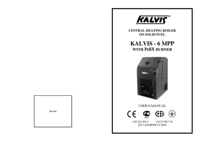
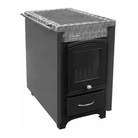
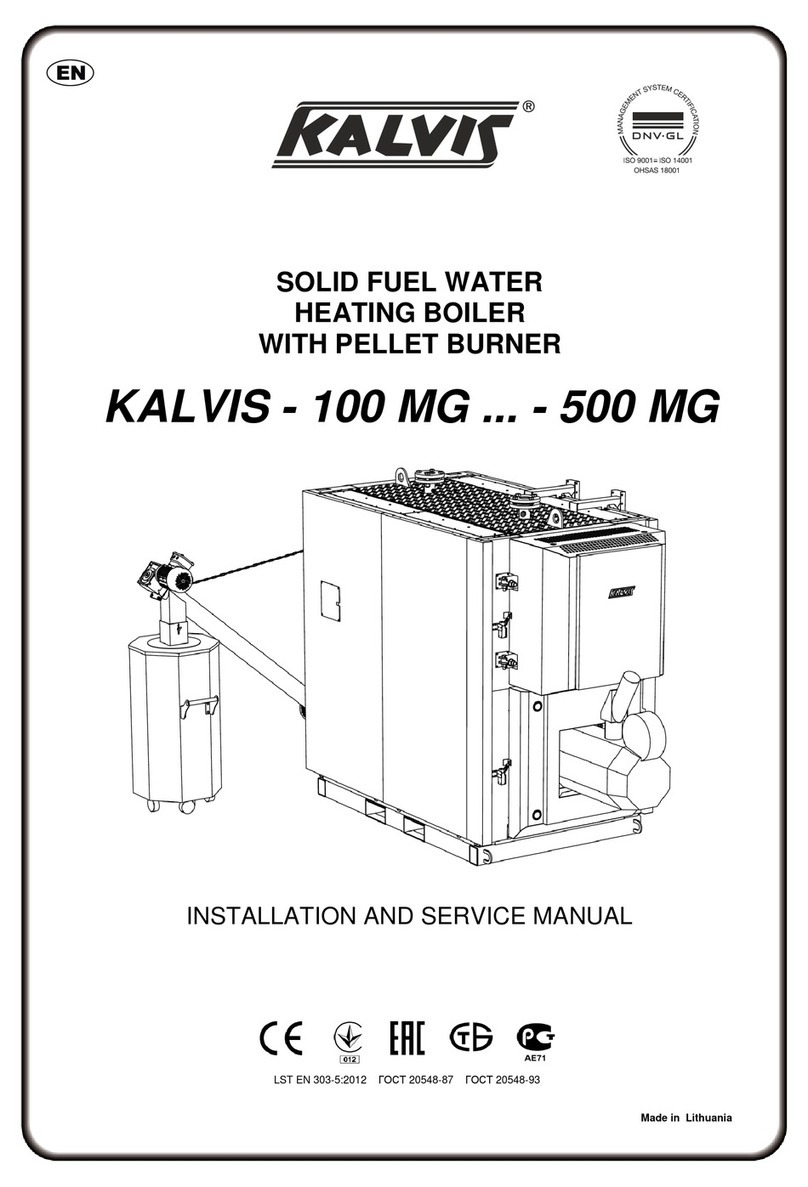
Kalvis K-2-70 Manual

CENTRAL HEATING
SOLID FUEL BOILER
KALVIS - 2 - 70
TECHNICAL CERTIFICATE, INSTALLATION
AND MAINTENANCE MANUAL
Made in Lithuania
Pagaminta Lietuvoje
Изготовлено вЛитве
LST EN 303-5:2012 ГОСТ 20548-87 ГОСТ 20548-93

- 2 -
CONTENTS
Dear Buyer....................................................................................................3
1. Recommendations ....................................................................................4
2. Intended use...............................................................................................4
3. Main technical data....................................................................................5
4. Design description.....................................................................................5
5. Transportation and storage........................................................................7
6. Boiler installation......................................................................................7
6.1. Fire precaution........................................................................................8
6.2. Requirements for chimney .....................................................................8
6.3. Connection to heating system...............................................................10
6.4. Air draught regulator installation .........................................................11
6.5. Connection of boiler cooling system....................................................11
7. Boiler operate..........................................................................................12
7.1. System preparation for heating.............................................................13
7.2. Boiler start up firing .............................................................................13
7.3. Air draught regulator adjustment..........................................................14
7.4. Boiler firing..........................................................................................14
7.5. Boiler extinguishing.............................................................................15
7.6. Boiler cleaning......................................................................................15
7.7. Frequently Asked Questions.................................................................16
8. Boiler disposal.........................................................................................17
9. Safety requirements.................................................................................17
10. Wearing parts.........................................................................................18
11. Fuel types and properties.......................................................................18
12. Scope of delivery...................................................................................18
13. Acceptance certificate ...........................................................................19
14. Warranty and guarantee service conditions...........................................19
Sales mark ...................................................................................................20
Boiler installation report.............................................................................21
Notes on warrant and non-warrant repairs performed...............................22
Application for guarantee service...............................................................23

- 3 -
KALVIS - 2 - 70 EN 2022.08.22
DEAR BUYER
We are very pleased that you have purchased our manufactured central
heating boiler. This versatile product is designed for space heating.
For combustion you can use a variety of solid lump well dried fuel. If desired,
the boiler is easy to adapt for stoking in mechanized way, with pellets. The
boiler is manufactured using modern materials and technologies.
We believe that if you carefully read this guide, properly install
and operate the boiler, it will cause no troubles in handling, and serve
you reliably, safely for a long time.
We wish you a warm and comfortable life!

- 4 -
1. Recommendations
In order the boiler served long and without troubles and you did not loose
the right for guarantee service, please observe the following main rules:
Attention: It is strictly prohibited to start up the boiler having no prior filled
boiler with thermal water.
1. Boiler installation, adjustment, operator training can be performed by a
firm, attested for such jobs and having qualified specialists or by
representative authorized by manufacturer. Installation note has to be done
in this certificate, installation report.
2. It is necessary to install the boiler into such heating system, which be able to
maintain the return water temperature not less than 60 ºC.
Attention: If you fail to meet this requirement, corrosion will occur due to
condensate which will significantly reduce service life of the body and
ceramic tiles.
3. Optimum operation of the boiler is achieved at close to nominal power.
4. If boiler power is too high and it has to be operated at lower than nominal
power, we recommend to install the boiler with accumulation tank.
5. Use fuel no damper than 25 %. In the case of higher fuel dampness, boiler
power drops, fuel consumption rises.
6. Having the heat demand lower than boiler nominal power, in order to
avoid the permanent loaded fuel smoldering (the resins may start
accumulating inside the boiler), do not load the furnace in full. We
recommend to load only one thirds of furnace.
Note. This operation manual is compiled following the requirements provided for
in EN 12171 Building Heating Systems. Operation, Maintenance and Use
Document Preparation Procedures. Heating Systems Needing no Trained
Operator.
2. Intended use
Solid fuel water heating boiler "Kalvis-2-70" (hereinafter referred to as the
“boiler”) is used for heating of various premises where central heating system is
installed with forced circulation and closed or open expansion system.
The boiler operates most efficiently under nominal taken thermal power,
if operating with lower power, the accumulation capacity is recommended to
use *5 (see page 5).

- 5 -
KALVIS - 2 - 70 EN 2022.08.22
3. Main technical data Table 1.
Boiler model
K-2-70
Nominal power (QN) *1
kW
70
Heated area
class B buildings *2
m2
602...1470
class C buildings *2
322...770
Fuel consumed
logs *3
Size of logs L x Ø, up to
cm
L50 x Ø15
Position of logs in furnace
lengthwise or
crosswise
Fuel loading openings size:
in front
mm
310 x 540
on top
mm
310 x 540
Furnace volume
dm3 (l)
467
Fuel charge combustion duration (QN) *4
hrs
4
Efficiency rate during operation at nominal power, no less than
%
82
Boiler class under EN 303-5
2
Boiler water capacity
l
198
Recommended min volume of accumulation vessel *5
l
1260
Water pressure in boiler, no more than
bar (MPa)
1,5 (0,15)
Max permissible water temperature
for opened heating system
ºC
95
for closed heating system *5
80
Min return water temperature during operation
ºC
60
Hydraulic resistance
mbar
8,5
Operating ambient temperature
ºC
3 ... 40
Temperature regulator adjustment range
ºC
65 ... 90
Adapted cooling coil type *6
AAG17
Cold water used for excessive heat
dissipation parameters: *6(*7)
pressure
bar
≤ 0,2
temperature
ºC
≥ 15
Required smoke draught from the boiler
no less than
Pa
35
no more than
40
Exhausted flue temperature at nominal output, up to
ºC
203
Exhausted flue quantity at nominal output
kg/s
0,058
Connection sockets dimensions:
flue channel
mm
Ø250
heating system
in
G2-B
drainage
in
G½
Overall dimensions (netto/brutto),
not bigger than
height
mm
1660 / 1863
width
mm
985 / 940
length
mm
1675 / 1720
Mass (netto/brutto), no more than (10%)
kg
1041 / 1066
*1Firing with 18 –20 % damp birch firewood. It is not recommended to fire with firewood damper than 25 %.
*2According to STR 2.01.02:2016 Energy Performance Projecting And Certification Of Buildings requirements
calculated amount of energy expressed for class B and C energy performance buildings.
*3As alternative fuel may be used coal, lump wood waste, chip or peat briquettes.
*4Fuel charge combustion duration depends on fuel type, moisture, outdoor temperature and other factors.
*5It is not recommended in the opened heating system to mount boiler with accumulation tank. Intensive boiler stoking
at 80 °C will cause the water inside of the boiler boiling, will appear the stranger noises.
*6For the boiler with installed emergency cooling system.
*7Available for installation having purchased separately (manufacturer UAB "Kalvis").
4. Design description
Note: Since boiler construction is under constant improvement, non-essential
deviations from this manual are possible.

- 6 -
Picture 1.
1. Hearth service door. 2. Primary air supply valves. 3. Internal cast iron door. 4. Hearth.
5. Decorative thermal insulation panels. 6. Fuel loading door. 7. Body. 8. Top loading cover. 9. Cooling
coil installation location *. 10. The pipe of the safety valve (G1). 11. Boiler lifting loop. 12. Service cover.
13. Ignition damper. 14. The inlet water pipe. 15. Flue with smoke draught damper. 16. Thermometer **.
17. Air draught regulator. 18. Pressure gauge **. 19. Removable spiral turbulators (16 pcs). 20. Fireclay
bricks. 21. Combustion chamber. 22. Secondary air supply valve. 23. Secondary air pipe. 24. Return water
pipe. 25. Water drain pipe. 26. Grounding screw. 27. Clean hole cover. 28. Bottom thermal insulation
panel. 29. Fire grate. 30. Ash drawer.
* Can be installed if purchased separately.
** The boiler is equipped with a thermometer and pressure gauge (0-120 °C, 0-4 bars) which are
indicative and do not replace the mandatory units for the heating devices.
The boiler body (7) (see picture 1), welded from special steel sheets, has cavities
in which water is heated. Boiler exterior is covered with decorative thermal insulation
shields. Boiler front has air draught regulator (17) controlling the primary air supply
valve (2), thermometer (16), pressure gauge (18) hearth service door (1), covering
inner cast iron door (3). Fuel loading chamber is closed by the door (6).
Inside the body, ignition damper is installed (13), opening the path for the smoke
to get directly to the chimney, it is used for boiler ignition and adding extra fuel; as
well as the fire grate (29). Under the fire grate, ash collection drawer is installed. In
the combustion chamber, fireclay bricks (12) are arranged as well as secondary air
pipe with openings for the air (16) maintaining high combustion temperature and
combusting CO. For more uniform distribution of heat between the heat exchanger
walls, removable turbulators (19) (16 pcs.) are installed.
In the boiler sidewalls, there are secondary air control valves (22) and ignition
damper adjustment handle installed.
In the back of the boiler, there is the water drain (25), return (24) and output (13)
water pipes, threaded G2-B, and the flue pipe with the smoke draught damper (15).
On the boiler, separately purchased safety valve (10) is installed, having an outer
one inch (G1) pipe thread.
In the boiler side wall, there is a flanged connector (9) used to install the boiler
cooling loop.
It is prohibited to change boiler construction without permission

- 7 -
KALVIS - 2 - 70 EN 2022.08.22
5. Transportation and storage
Boilers are stored and transported fastened onto wooden pallet and twisted with
polythene film, if nothing else is agreed in the supply agreement.
Boilers are allowed to transport exclusively in vertical position with any kind of
covered transport. If weather is dry, open transport is allowed. Extra measures have to
be taken to protect boilers from falling down, scratching against each other. During
loading/unloading/transportation it is prohibited to beat, turn, throw the boilers.
Boilers are stored in dry premises, without presence of chemically active substance
gases.
Note. Product packing (wooden pallet and polythene film) disposal actions shall meet
the environmental requirements and rules of the user’s country. In the extreme
case wooden pallet can be used as fuel for the boiler.
Picture 2. Boiler packing for transportation
6. Boiler installation
Boiler is to be installed in the premises meeting the relevant requirements of the
country where boiler has to be installed.
Boiler firing requires much air, therefore is necessary to ensure the sufficient fresh
air intake in the boiler operate premise.
Boiler is to be positioned upright or declined to front by no more than 1o. Premise
floor must be even, not flammable and capable to withstand the load up to 1,3 t/m².
It is recommended to install fume extraction hood above the boiler.
It is prohibited to install boiler in the living rooms or corridors.
Prior connecting the boiler to heating system and chimney, take into consideration
the fact that the boiler will has to be maintained (cleaned, adjusted etc.). Minimum
distances between the boiler and walls necessary for its maintenance and fire
precaution are shown in picture 2.

- 8 -
6.1. Fire precaution
•Put the boiler on the refractory base;
•Metal tubes are used to connect boiler to chimney, these tubes have to be made of
metal sheet no thinner than 1,5 mm and covered with heat insulating material.
Warning! In the case draught in the chimney is too strong and if wood chips,
sawdust, chaff or another powdery materials are used as fuel, smoldering
unburned fuel particles (sparks) can come out of the chimney during fuel loading
or after fuel has burnt and having shaken remaining fuel.
If roof or its constructions are made of easily flammable materials or there are
similar constructions, building materials, fuel etc. found closer than 20 m from the
chimney, it is strictly prohibited to use the mentioned powdery materials!
6.2. Requirements for chimney
Chimney construction and boiler connection to chimney options see picture 3.
Requirements:
•chimney draught shall be no less than it is specified in the main technical data
table (see page 5);
•hole of the chimney shall have cross-section no less than boiler's flue cross-
section;
•boiler needs the separate chimney hole. Nothing else should be connected to the
same hole;
•if the chimney is connected with extra elbow, its cross-section cannot be less than
the cross-section of fume escape from boiler hole with bending radius no less than 100
mm;
•tube between the boiler flue and chimney shall be no longer than 1,5 m, it must be
rising towards the chimney, providing the possibility for its cleaning;
•seal the gaps at connection and chimney entrance places.
Note that:
•smoke, after getting into the chimney from the boiler flue pipe, continues cooling,
vapor, contained in the smoke, condenses by settling on the chimney walls,
especially in unheated loft and external part of the chimney;
•acids of the condensate and heat-cold erosion can disintegrate chimney in a couple
of years;
•not cleaned soot can ignite in some time and, if the chimney is unmaintained or
roofing is easily flammable, it may cause the fire.
We recommend:
•to install stainless steel insert inside the chimney. Correctly installed insert protects
chimney from condensate impact and improves draught;
•the insert shall not reduce cross-section of the chimney hole significantly;
•joints between the parts of the insert have to be sealed together (not by soldering);
•the condensate collector has to be installed in the bottom;
•fill the gap between insert and chimney walls, at least where chimney is outside
the building, with fireproof heat insulation material. Plaster the gap on the top and
cover with tin at a gradient;

- 9 -
KALVIS - 2 - 70 EN 2022.08.22
Picture 3.
•winterize the chimney with the fireproof heat insulation material in a cold loft.
•if the fire is set out inside of the chimney, close the air feeding to the chimney and
call firemen;
•make the openings in the chimney joint in a suitable place, for periodical cleaning
of soot (once a month).
•it is recommended to have boiler examined by qualified chimney expert once a
year.
Notice. In the case of poor chimney draught, as a last resort to improve it, all or a
part of turbulators (19), located between the heat exchanger walls can be
removed, thus dramatically reducing boiler operating performance.

- 10 -
6.3. Connection to the heating system
The many of heat consumer's boiler houses connection diagrams are becoming
increasingly complexes. There are connected a few of alternative heat generators - the
solid fuel or gas boiler, extra pellet burner, electric heating system, thermal pumps,
solar collectors and etc. For the premises heating there are used a several of radiators,
heating floor or air heating, there are mounted the accumulation tanks, various
equipment of the water preparation.
Therefore the proper setting of the boiler and formation of the boiler connection
diagram according to the customer requirements is allowed only for the qualified
engineers and experienced installers. The picture 4 is showing only the part of the
recommended boiler's connection to the heating system diagram, which ensures the
return water temperature not lower than 60°. Diagram not contained the auxiliary
technological equipment (valves, expansion vessel and other).
Picture 4.
The part of recommended boiler installation diagram, performing which, ensures the long
service life of the boiler, not allows to form the condensate. There are not shown the auxiliary
technological equipment of the boiler house (expansion vessel, valves and other).
Requirements for the connection:
•The valves, disconnecting the boiler from heating system installed in the system
tubes, must be fully opened. In order to avoid accident through negligence, take off
the grips of the valves after having opened them;
•In order to avoid the condensate formation, which can significantly reduce service
life of the boiler, there should be installed the such heating system, which enables
maintaining the return water temperature of no less than 60 C;
•It is necessary into the heating system, as much closer to boiler, to install the
protective valve (G½B), preventing the boiler housing against to pressure bigger
than 1,5 bar (0,15 MPa). In between the boiler and protective valve there is not
allowed to install any shut-off fittings;
Notice. If the system pipes contained the shut-off valves, which disconnects boiler
from the heating system, they should be fully opened. In order to avoid any
accidents caused by inattention, it is expedient to take away the valves grips,
having the valves fully opened.

- 11 -
KALVIS - 2 - 70 EN 2022.08.22
•Boiler can be connected into a heating system with membrane expansion reservoir,
vessel's permissible operation pressure could be up to 10 bar, air pressure should be
equal to the system pressure, for example 0,6 bar. Prepares the opened type heating
system, instead of membrane expansion vessel, there could be used the expansion
vessel of opened type.
•If boiler operates at the power less than the nominal power specified in the
technical specifications, the efficiency of the boiler reduces, environmental indices
become worse. Therefore it is recommended to use the boiler connection diagrams
with accumulation tank.
Notice. We not recommend to install the boiler with accumulation tank having the
opened type heating system. The boiler intensive firing, when temperature is
rising close to 80 °C, may cause the water boiling inside of boiler, may
appear as well the extraneous noise.
Attention! Having a risk of freezing or within the boiler repair, the water from the
system is drained over to drain socket (25) (see picture 1).
6.4. Air draught regulator installation
The air draught regulator (32) (see picture 1) (hereinafter referred to as regulator)
is screwed in, for sealing using oakum or sealing tape.
Connect the chain with primary air supply dampers (27) (see also chapter 7.3).
6.5. Connection of the boiler cooling system
According to the requirements of LST EN 303-5 standard par. 4.1.5.11.3, for
boiler operation it is necessary to install the devices used for dissemination of heat
excess, if, for the some reasons, the normal heat take-away is disturbed in the
heating system, in order to not to exceed the max boiler water temperature.
Note. For the boilers, operated in open expansion system, it is not necessary to install
the device for heat surplus dissipation in the boiler, because heat surplus is
dissipated in the form of steam through open expansion vessel.
For the boiler protection against to overheating, it is possible to install into the its
housing the emergency cooling coil. When the boiler heats over 95 C, temperature
valve opens and cold water, flowing from water supply through the coil, cools the
boiler. The cooling water is then directed to the sewage through pipes no thinner than
those installed on exit from the coil (water has to flow freely to the sewage).
During cooling coil installation:
•after having been unscrewed the screws, take off the cover from the trimming
shield (or brake perforation away);
•after having been unscrewed the nuts, take the blind away;
•replace the sealing ring;
•insert and screw in the cooling coil (according to directions in the figure).
Attention ! Work carefully - the edges of the decorative shield's opening may become
sharp, do not injures.

- 12 -
Picture 5.
a) cooling water discharge branch (G ¾)*
b) temperature sensor screwing socket (G ½)
c) cooling water supply branch (G ¾)*
* a and c connections can be inter-changed
The temperature valve is connected to the cooling coil
(see recommended boiler house connection layouts).
Temperature valve has to be connected with no less than ¾
inch pipes, temperature sensor of the valve is inserted into
socket „b“ (see fig. 5).
The temperature valve used shall have the following
parameters:
Min water temperature 10 ºC;
Opening temperature 95 ºC;
Max water temperature 110 ºC;
Max water debit 6,5 m³/h;
Max water pressure 10 bar.
If the electric power supply is interrupted in the house with the local water supply
system (water is supplied by hydrophore) boiler overheat can occur (stopped heating
system circulation pumps) it is necessary to have the extra water supply to the cooling
system.
Attention ! Emergency cooling coil cannot be used for hot water preparation.
7. Boiler operate
Boiler can be operated by adult persons well familiarized with boiler construction
and this technical certificate.
The recommended fuel moisture should not exceed 25 %.
Attention! When boiler is fired with damp fuel (firewood or chips), formed condensate
combines with combustible gases resulting in acids, which reduce service life of
the boiler significantly. Besides that, this is inefficient, because given efficiency
rate cannot be reached, so much more firewood is consumed.
If damp fuel is used for stoking, the specified efficiency factor cannot be reached,
so much more firewood is needed.
Notice. User is allowed at its discretion to use other solid fuel, but requirements of
chapter 6.1 should be not violated and with meaningless claims to the
manufacturer on the output.
Notice. If in the room, where the boiler is operated, there are more air using
equipment, than the sufficient fresh air intake into the room must be ensured for
all equipment.

- 13 -
KALVIS - 2 - 70 EN 2022.08.22
It is prohibited! To fire the boiler with:
- small fraction (dust) of waste wood, because is a risk of explosion or sparks
emission from the chimney;
- rubbish (household waste);
- with opened ignition damper (8).
Attention! In order to prevent the smoke entering in the room, the upper fuel loading
cover (8), furnace's and fuel loading doors (1, 6) and service covers (12, 27) has
to be tightly closed, except in cases of boiler ignition, refueling or boiler
cleaning.
Attention! The ignition damper (13) (see picture 1) within the boiler firing must be
fully closed !
Attention! The flue duct (15), and other boiler surfaces not covered by the thermo
insulation shields (5) becomes very hot during operation. Do not touch them.
Attention! Don’t overheat (boil) water in the boiler.
7.1. System preparation for heating
Prior to boiler start firing make sure does the system is filled with thermal water
and de aerated. We recommend to apply the de salted, soft, or at least rainwater. If
there will be used the prepared "soft" water, than the boiler housing will serve for the
longer time. As well it is necessary to make sure does the valves, which are
disconnecting the boiler from the system, are not closed.
7.2. Boiler start up firing
Before starting the boiler, open the smoke draught damper (15) (see picture 1),
ignition damper (13), through the doors (1 and 3) put crushed dry wood or chips onto
fire grate (29) and set on fire. Secondary air hole valves (22) have to be closed. Valves
are adjusted when temperature in the boiler reaches 60 °C.
When combustion starts, after ignition load is burnt, add more fuel into loading
chamber (see below how to add more fuel), close the ignition damper (19).
The more fine chopped logs burns more effective and increases the boiler output.
Place firewood loosely into the combustion chamber (furnace) (30) so it could sag
down to the bottom of the chamber freely.
If coal is to be used, take 5 - 10 kg firewood and top with 10 cm coal. Coal is to be
poured layer by layer in a number of times, depending on fuel quality and desirable
heat volume.
Attention! When firing the boiler for the first time, also after the long period of non-
operation (after summer season), it is necessary to heat up the refractory
concrete parts for the moisture contained inside, converting into the steam, did
not disintegrate such parts. For this purpose there to be ignited not big amount of
the fuel. Fuel volume must be such that it will burned within 20 –30 min.
After 2 hours the boiler is ready for normal operation.

- 14 -
7.3. Air draught regulator adjustment
After the boiler reaches desirable temperature (70 ÷ 90 °C), comparing with the
readings of thermal gauge (16) installed in the boiler, set regulator (17) at similar
temperature
Note. Regulator’s dial misalignment with readings of thermal pressure gauge is
possible.
Shorten the chain so, that the primary air supply valves (2) would be closed or the
gap would be not bigger than 2 mm. Set the desired temperature by turning regulator
knob to relevant position.
As well the boiler may be supplied with different regulator, which has different
temperature's range marking.
7.4. Boiler firing
For adding more fuel into the boiler:
-Open the ignition damper (13) (see picture 1);
-Open hearth service door (1) and check fire grate (29) holes for clogging, preventing
air to enter the hearth (4). If needed, use poker to move the bottom layer of the fuel.
Close the door (1);
-By turning air draught adjuster handle (17), close the primary air supply valves (2)
located in the door;
-Open a little fuel loading door (6) and keep for 15...20 seconds (for how long to
keep the door a little opened, observe, when there is no more smoke in the
chamber);
-Open the door fully and add more fuel in the hearth;
-Tightly close fuel loading door (6) and ignition damper (13).
-According to the selected temperature, with the means of air draught adjuster (17),
open the primary air supply valves (2).
Notice. We recommend to refuel only having completely burned previous fuel load.
Otherwise refuel only in urgent cases if there is no other option.
Secondary air
The combustion process control not having the measuring devices could be done
by monitoring the color of the smoke going out of the chimney. The combustion
quality to be checked at water temperature ≥ 80º C. If the combustion process is good,
smoke than is thin, grey. If the smoke is thick and dark, means that fuel is not fully
burn, secondary air supply is insufficient. In such case open more the secondary air
valves. Using the birch logs moisture contain 25 %, the smoke ecological pollution is
the lowest (the carbon monoxide (CO) emission) is obtained when the secondary air
valves are open by 11 mm. Using other type of fuel for the secondary air supply valve
adjustment we recommend call to specialist, which have the gas analyzer. It is
appropriate to do so having the big quantity of homogeneous high-quality fuel.
Firing efficiency
During combustion remains the ash, which covers the fire grates. Accordingly
drops the burning intensity and boiler output. Therefore the fuel need to be poked. The

- 15 -
KALVIS - 2 - 70 EN 2022.08.22
burning coal to be pocked via poker through the gaps of the inner door. Large volume
of generated ash prevents primary air from entering, so ash has to be removed timely.
Lower door has two primary air valves installed. Upper valve assists with air
supply when ash clogs the ash holes.
If there is no need to open fuel loading door (6 and 8) during combustion, don’t
open it.
Boiler combustion needs much air, so enough volume of air has to enter into the
premises where boiler is installed.
Notice. In case of lower heat demand then boiler nominal output, in order to avoid
the permanent loaded fuel smoldering (inside of boiler may accumulates the resin,
do not load with fuel full furnace. We recommend to load one third of furnace.
Notice. When boiler is started to operate, during firing, on the internal boiler walls,
when there is no sooth layer yet, when firewood burns, water condensate forms,
which can look like the boiler is not tight and leaks water. Water steam condensate
disappears when the water temperature in the boiler raises up to 70 –80 °C with
the help of 4-way mixing valve. It is recommended to maintain water temperature
in the boiler as high as possible. If return water temperature is less than 60 °C,
water steam condenses on internal surfaces of the boiler, which combine with
combustion products and form chemically aggressive acids, under effect of which
boiler service life can be reduced significantly. In order to make sure that the
boiler is tight, stock it at high intensity for several hours, then, stop stocking and
make sure if amount of condensate increases. If it doesn’t, the boiler is tight.
Attention! If boiler is operated incorrectly, fuel is unsuitable, low chimney draught,
the dampers installed in the boiler can get stuck, so during the heating season
move the dampers: open and close several times all the valves installed in the
boiler.
7.5. Boiler extinguishing
During usual operation, boiler is self-extinguishing when fuel charge completely
burns out. If boiler has to be extinguished in the forced way, firstly, remove fuel from
the furnace (4). Throw burning fuel into a vessel with water –this will reduce smoke
in the premises. During forced extinguishing, open roods or windows to assure good
ventilation of the premises.
Attention! It is prohibited to pour the water onto burning fuel in the furnace.
7.6. Boiler cleaning
Ash, accumulated under the fire grate (29) (see picture 1), may prevent air supply
to the furnace (4). So, no rarely than before each second firing, remove the ash from
the ash tray (30) and scoop remaining ash.
Attention ! It is allowed to clean the boiler, remove the ash tray and scoop up the
remaining ash, having only the boiler fully extinguished and cooled down.
In order to assure the efficient boiler operation, it is necessary to clean periodically
the sooth from the internal surfaces of the boiler. Intervals between cleanings depend

- 16 -
on fuel quality (especially moisture), burning intensity, chimney draught and other
circumstances. It is recommended to clean boiler heat exchanger and combustion
chamber when sooth layer is up to 3 mm thick, but no rarely than 2 –3 times per
month. When cleaning, remove service covers (27) (see Fig. 1) and open the
remaining covers and doors; remove turbulators (19) and carefully clean the boiler’s
internal surfaces with scrapper and brush.
In order to remove the hardened scale, it is recommended to use the chemical
cleaners.
It is recommended to clean the chimney no rarely than every year and necessarily
before start of the heating season.
Notice. Is recommended to have a annual inspection of the boiler carried out by
qualified specialist of boilers supervision.
7.7. Frequently Asked Questions
I. What may happen when electricity breaks down during boiler’s working
process?
If there's no forced circulation, then water might get boiled, threat of the overheat
of the boiler, there's threat of explosion of boiler or pipes, threat of being scalded.
a) Lower intensity of burning process: close primary air valve; close fume valve
as much as you can, avoiding fume access to the premises;
b) In case of emergency, extinguish the boiler by removing fuel out of the
boilers burning chamber (put burning fuel to the utensil with water to get as
little fume as possible accessing the premises; open windows and doors). Do
not pour water into burning chamber, water can damage the boiler completely.
c) At winter time, if electricity failure lasts and there's threat of getting frozen,
let out the water from heating system and pipes.
II. Why during combustion process there's outsider noises (boiling water noise),
external decorations and flue changes their color?
Boiler is working above the nominal power, circulation pump is out of the order.
a) Check if smoke cessation and ignition valves are closed.
b) Check if air draft regulator is set properly and it's not set for too high
temperature.
c) Check if chimneys thrust is not to strong, half-shut fume thrust valve.
d) Maybe there's no water circulation: check if circulation pump is in working
order; check water pressure (level) in the system; check if systems is vented
properly; check for close system valve; check if water filters are not blocked.
e) Check out for worn out of door or lid sealing parts, replace them if needed.
III. Why boiler weeps, the fire goes out, smoke penetrates out of the boiler?
Boilers operating power is set to low or there's not enough draught from chimney,
that's why condensate accumulates.
a) In case of lower demand of heat, put less fuel to make sure that fuel is
burning not smoldering.
b) Use proper fuel - dry logs.

- 17 -
KALVIS - 2 - 70 EN 2022.08.22
c) Check if inbound waters temperature is not too low as has to be, adjust
mixing valve in order to assure inbound water temperature not lower
than 60 C.
d) Check chimneys draught, clean chimney, flue channels and the boiler itself;
check for ash level under the fire grades and clean.
e) Check out of door or lid sealing parts, replace them if needed.
IV. Why after boiler is lighted water pressure increase?
When boiler is heated up to nominal power water pressure exceeds permissible
limits.
a) There's possibility that extension vessel is not working or it's too small.
b) Maybe there's no water circulation: check if circulation pump is working
correctly; check water pressure (level) in the system; check if systems is vented
properly; check for close system valve; check if water filters are not blocked.
c) There's possibility that during fill up of the system permissible pressure limits
were exceeded, lower the pressure.
8. Boiler disposal
Dispose the boiler after expiration of its service life or if it is uninstalled due to
other reasons. Boiler is constructed from various materials, so:
•Bring electric appliances, if present, to electric appliances recycling organization;
•Metal parts go to metal scrap;
•Remaining materials go to landfill or waste storage sites.
Note. Disposal actions shall be in line with laws and rules of user’s country.
9. Safety requirements
The following is prohibited:
•To operate boiler without having filled heating system with water. Water in the
heating system has to be protected from freezing;
•To connect boiler into closed system without safety valve;
•To close supply or return water line valves when boiler is in operation;
•To dry fuel or other easily combustible materials near or on the boiler;
•To fire the boiler with the help of easily combustible fluids (petrol, kerosene etc.);
•To operate boiler with open doors or covers;
•To pour non-extinguished coal and ash near living or auxiliary buildings;
•To entrust boiler maintenance to minors or non-trained persons;
•To operate boiler without grounding the case;
•To touch electric installation of the boiler.
The following is necessary:
•Periodically (twice a year) check if grounding is working properly;
•Before cleaning the boiler disconnect it from electric power.

- 18 -
10. Fast wearing parts during boiler operation
Sealing parts from glass fiber; cast iron fire grates (29) and door (3); refractory
concrete bricks (20) can become worn, burn out, disintegrate while in use.
These parts are available for purchase at boiler manufacturer or its agents.
Note. It is advisable to use only manufacturer’s original spare parts.
11. Fuel types and their properties
Combustion heat of absolutely dry wood actually doesn’t depend on wood spice
and is equal about 4500 kcal/kg. So, as to assess different wood species, one should
take into consideration their comparative weight. Weight per cubic meter of various
firewood species is as follows:
- oak firewood - 500 kg;
- birch firewood - 450 kg;
- fir firewood - 330 kg;
- aspen firewood - 330 kg.
The damper is firewood the less is its caloric content. Wet firewood caloricity
reduction, compared with dry firewood (dampness ~20 %) is as follows:
- 30 % moisture - 10 15 %;
- 50 % moisture - 35 40 %.
Just cut tree contains 35 60 % water. Tree cut in the beginning of winter contains
least quantity of water. Hardwood contains less water.
Wood has to be cut and split to make firewood. Firewood, after one year spent in
garret is of 20 25 % moisture.
After two years it is 13 17 %, and this means that after drying less fuel is needed
than combustion with damp firewood.
Equal weight of firewood and peat give similar heat quantity.
1 kg of coal gives 2 3 times more heat than 1 kg of firewood, due to this reason;
coal change into hearth should not exceed 10 kg.
Volume of air needed to combust 1 kg of firewood is 4 5 m3, for coal –10 m3.
The poorer quality is fuel, the more ash it generates.
Combustion of 1 kg average caloricity coal gives about 6500 kcal (7,56 kWh).
12. Scope of delivery
1. Boiler "Kalvis-2-70" - 1 pcs.
2. Air draught regulator - 1 pcs.
3. Scraper - 1 pcs.
4. Ash removal scoop - 1 pcs.
5. Poker - 1 pcs.
6. Boiler technical passport - 1 pcs.
7. Wooden pallet for transportation - 1 pcs.
Notice. Security valve, cooling coil with temperature valve are not included into the
scope of delivery - to be purchased separately.

- 19 -
KALVIS - 2 - 70 EN 2022.08.22
13. Acceptance certificate
Solid fuel heating boiler "Kalvis-2-70" factory No.____________ meets drawings,
EN 303-5, ГОСТ 20548-87 and ГОСТ 20548-93 standard requirements and is fit for
use.
Boiler was tested with 4 bar (0,4 MPa) pressure.
Manufacturing date ___________________________
Supervisor ___________________________
14. Warranty and guarantee service conditions
Manufacturer guarantees that product is in line with technical documentation
requirements.
•If you correctly will install and operate the boiler in accordance with these
instructions, the following guarantee service period will be applied from the date
of purchase:
- for boiler case - 48 months.
- for completing parts - 12 months.
- for wearing parts (see chapter 10) - 6 months.
•Please take care for the installation works performing person or firm filled the
installation report.
•Manufacturer obliges to eliminate failures occurring due to its fault during the
mentioned period for free.
•Manufacturer takes no obligation for boiler operation and related consequences,
grants no warrant if the boiler is inadequately selected, poorly installed (see
chapter 6) or operated (see chapter 7) and this is found out during the visit at user.
In this case user shall pay for technicians’ arrival and repairs!
•No rarely than once a year perform revision of the boiler and its control
elements with the help of adequately qualify specialists.
•Keep purchase receipt or invoice throughout the warrant period.
•For warrant repairs apply to this service providing company, specified by seller.
•In the case of boiler failure, apply to the specified service; upon its arrival fill
the application form shown on the last page.
•We ask user to take care for after warrant repairs service employee made
relevant record in this certificate “Notes about warrant and non-warrant repairs”
and filled warrant repairs report
I familiarized with warrant repairs conditions. I am informed that in the case
boiler is installed and operated without observing the requirements given in this
manual otherwise I loose the right for warrant repairs.
Buyer:
(name, surname, signature)

- 20 -
SALES MARK
Boiler was sold by:
Company:
Sales date:
Address:
Telephone:
In the case of failure please call:
Company:
Address:
Telephone:
Manufacturer
UAB “Kalvis”
Pramonės 15, LT-78137 Šiauliai, Lietuva (Lithuania)
Telephone: +370-671-88891
E-mail: prekyba@kalvis.lt
Warranty service
Provided by a partner you bought a product
Table of contents
Other Kalvis Boiler manuals
Popular Boiler manuals by other brands

Worcester
Worcester Greenstar 12Ri instruction manual

Rinnai
Rinnai Q series troubleshooting manual

Viadrus
Viadrus HERCULES Green Eco Therm Series manual

Baxi
Baxi Maxflow Combi WM User operating instructions

Dunkirk
Dunkirk XEB-2 installation manual

Viessmann
Viessmann Vitodens 200-W System installation instructions

Worcester
Worcester GREENSTAR HIGHFLOW 440CDI ERP Installation, commissioning and servicing instructions

Nova Florida
Nova Florida DRAGO DUAL 23 Installation, use and maintenance

KOB
KOB PYROT KRT 150 Operation and maintenance instructions

Buderus
Buderus Logano plus GB102S User instructions

Lochinvar
Lochinvar Condensing Boiler Warranty

Baxi
Baxi 100 He User operating instructions