KAM KAP2020 USB User manual

MADE IN CHINA
Due to continuous product development, please ensure that you have downloaded
the latest instruction manual for this product from the Kam website at www.kam.co.uk
MANUAL VERSION 1.0
03/08/12
For the latest updates and information on the entire Kam range visit:
www.kam.co.uk
Kam products are manufactured by: Lamba plc, Unit 1, Southfields Road, Dunstable, Bedfordshire, United Kingdom LU6 3EJ
Telephone: (+44) (0)1582 690600 • Fax: (+44) (0)1582 690400 • Email: mail@lambaplc.com • Web: www.lambaplc.com
Due to continuous product development, specifications and appearance are subject to change. © Copyright Lamba plc 2012. E&OE.
KAP2020 USB
Rack mountable 4 channel mixer with USB playback

Thank you for purchasing this Kam product, we are sure that it will serve you for many years to come.
To optimise the performance of this product, please read these operating instructions carefully to familiarise
yourself with the basic operations of this unit. Please retain them for future reference.This unit has been tested at
the factory before being shipped to you.
To prevent or reduce the risk of electrical shock or fire, do not expose the unit to rain or moisture. To prevent a fire
hazard, do not expose the unit to any naked flame sources. Unplug this apparatus during lightning storms or if it is
unlikely to be used for long periods of time.
When installing the unit, please ensure you leave enough space around the unit for ventilation. Slots and openings
in the unit are provided for ventilation to ensure reliable operation of the product and to protect it from overheating.
To prevent fire hazard, the openings should never be blocked or covered.
If the unit is powered by the mains, always handle the power cable by the plug. Never pull out the plug by pulling
on the cable. Never touch the power cable when your hands are wet as this could cause an electric shock. Do not
tie a knot in the cable. The power cable should be placed such that it is not likely to be stepped on. A damaged
power cable can cause a fire or give you an electrical shock. Checkthe power cord periodicaly, if you ever find that
it is damaged, replace it before using the unit again. Contact your retailer for a replacement.
The voltage of the available power supply differs according to country or region. Be sure that the power supply
voltage of the area where this unit is to be used meets the required written on the unit.
The lightning flash symbol inside a triangle is to alert the user to the presence high voltage within the
unit’s enclosure that may be of sufficient power to constitute a risk of electrical shock to persons.
Caution: to prevent the risk of electric shock, do not attempt to open the unit. No user-serviceable parts
inside. Refer all servicing to qualified service personnel.
The exclamation mark inside a triangle is intended to alert the user to the presence of important operating
and maintenance instructions in the literature accompanying the appliance.
Select the installation location of your unit carefully. Avoid placing it in direct sunlight or locations subject to
vibration and excessive dust. Do not use the unit where there are extremes in temperature (below 41ºF / 5ºC or
exceeding 95ºF / 35ºC).
Unpacking and safety Please unpack your new product carefully. Your new product should reach you in perfect
condition. Please check that no damage has occurred during transit. If any damage is found, do not operate your
unit. Please contact the retailer you purchased it from immediately. If there is any damage to the mains cable do
not use the device. Always disconnect the unit from the mains supply when carrying out any cleaning of the unit.
Manufacturer declarations
In compliance with the following requirements: RoHS Directive (2002/95/EU) and WEEE Directive (2002/96/EU).
If this product is ever no longer functional please take it to a recycling plant for environmentally friendly disposal.
CE declaration of conformity
R&TTE Directive (1999/5/EU), EMC Directive (2004/108/EU), Low Voltage Directive (2006/95/EU).
The declarations are available on application from certification@lambaplc.com
Before putting the devices into operation, please observe the respective country-specific regulations.

Unpacking
Warning: After unpacking, and before plugging the AC cord in the wall outlet, check whether the AC mains voltage
and frequency is the same as this product (AC220-250V~ 50Hz). If the specified voltage or your AC plug should
not match the local conditions, do NOT plug the AC cord into the wall outlet and contact you dealer immediately.
Back Panel
1. Mains input and fuse holder. Use the supplied power lead to connect the unit to AC mains. Make sure
voltage and frequency stated on the unit comply with your local AC supply. The fuse can be accessed by the
small drawer in the AC inlet. To change the fuse, unplug the AC cord first, pull out the fuse drawer and
replace the fuse ONLY with a fuse of SAME voltage and rating. If the fuse blows again after replacement,
please contact your nearest retailer to get the unit checked out.
2. Power switch. Switches the unit on and off. Make sure to switch the unit off when not in use.
3. Balanced output. This is a balanced stereo output carrying the main output signal controlled by (32).
4. Main stereo output. This is an unbalanced output carrying the same signal as output (3).
5. Subwoofer output. This is a balanced mono output for connecting an amplifier driving a subwoofer system.
Please note that the subwoofer output runs in parallel to the main output, hence while the subwoofer upper
frequency limit can be adjusted by means of control (6), no lower frequency limit is introduced to the main
output (3).
6. Crossover frequency adjustment of internal active crossover. Together with the level control (7), this
allows to set the upper frequency limit of the subwoofer output (5). Choosing an appropriate crossover
frequency will avoid unpleasant interference effects with your main program speakers. Check your subwoofer
system specification to determine a suitable frequency.
7. Level control for subwoofer output (5).
8. Booth stereo output. This is an unbalanced output carrying the booth signal controlled by (33). This output
can be used for a 2nd zone which needs independent volume control, such as the DJ booth or the seating
area of a club.
9. Record output. This is an unbalanced stereo output carrying the same signal as the main output (3/4), but
not influenced by the main volume control (32). This is normally used for recording the output to an external
tape, CD or memory device.
10. FX Loop. These two ¼’’ jack (6.35mm) connectors allow you to add a stereo effects processor to the master
signal path. They interact with the top panel controls (41, 42, 43, 44 ). Please note that this effects loop is
NOT an insert path, but a parallel effects path, meaning effects like filters (which are of serial nature) are not
as effectively processed by the effects loop as effect like reverb or delay (which are of parallel nature).
11. Line inputs. These RCA connectors provide inputs for line-level signals to the assigned channels.
12. Phono Inputs. Depending on the position of the selector switches (13), these RCA connectors provide the
following inputs: (A) Position “PHONO”: input for phono-level signals to the assigned channels, featuring the
necessary RIAA equalization. (B) Position “LINE”: input for line-level signals to the assigned channels. Note
please ensure the correct line / phone level is selected before connection as failure to do so may cause
damage to the unit.
13. PHONO/LINE selector switches for PHONO inputs. These switches change the sensitivity of the PHONO
inputs between PHONO (RIAA equalized) and LINE level.
14. Microphone inputs for MIC1. This is a balanced ¼” jack (6.35mm) connector without phantom power
provision, hence only suitable for dynamic microphones. Please note that this connector is in parallel to the
top-panel mounted balanced Combo (XLR + ¼” jack) 6.35mm connector (18).
15. Microphone inputs for MIC2. Same as (14) but for microphone 2.

16. Talkover threshold control. The setting of this control determines at which microphone level the automatic
talkover starts to reduce the master output level. In addition, the amount of reduction can be determined with
the top panel TALKOVER control (34).
17. USB input. This allows the use of the mixer’s internal soundcard by connecting a PC to the mixer through this
port and routing the audio output signal to INPUT1 by means of the top-panel selector switch (22). Please
note that this is NOT a host interface with audio decoder, so this interface is not intended to directly connect
hard disks or USB sticks with audio content. This connector is only designed to act as an external USB 1.1
soundcard, to be connected to a PC. Apart from replaying audio from the PC, this interface is bidirectional
and also allows you to record the signal present at the record output (9) digitally into the PC. Also note that
this USB connection is not related to the top-panel USB socket (45).
Top Panel
18. Microphone inputs for MIC1+MIC2. This is a balanced Combo (XLR + ¼” jack ) 6.35 mm connector without
phantom power provision, hence only suitable for dynamic microphones. Please note that this connector is in
parallel to the rear-panel mounted balanced ¼” jack connector 6.35mm (14, 15).
19. On/Off (ON AIR) switches for microphone channels. Turns microphone channels on/off
20. Microphone level control. Sets the microphone level Microphone equalizer. Allows the adjustment of the
tonal balance for each of the two microphone inputs in three voice-specific frequency bands with an
adjustment range of ±12dB.
21. Microphone equalizer. Allows the adjustment of the bass, mid & treble frequencies of each microphone
channel.
22. Input selector for stereo channels. Switches between the inputs as indicated on the front panel. A LED
indicates the pressed position.
23. Gain control of input channels. Allows adjustment of the input sensitivity to compensate for different source
volumes.
24. 0dB LED. Facilitates proper setting of input gain levels. The LED lights up when the signal after the Gain
control (23) reaches 0dB.
25. Stereo channel equalizer. Allows the adjustment of bass, mid & treble for each of the stereo inputs with an
adjustment range of -26/+12dB, thus providing a virtual “kill” function for each frequency band if set to
minimum.
26. Channel fader for input channels. A high-grade dual rail 60mm fader adjusts the volume of the respective
channel.
27. CUE switch for stereo channels. Assigns the respective channel to the headphone bus for pre-fader-
listening (CUE). A LED indicates the pressed position.
28. Crossfader assignment switch. Allows to route a desired channel either to X (left crossfader side) or to Y
(right crossfader side) or directly to the master control without crossfader control
29. AUX Input for channel 4. This is a 3.5mm Mini-jack stereo socket which allows to connect sources like MP3
players etc. without removing the mixer from its mounting position.
30. Crossfader. A high-grade dual rail 45mm fader determines the mix ratio between the stereo signals routed to
X (assigned to the left crossfader side) and Y (assigned to the right crossfader side). If no signals are
assigned by means of the switches (28), the crossfader is disabled.

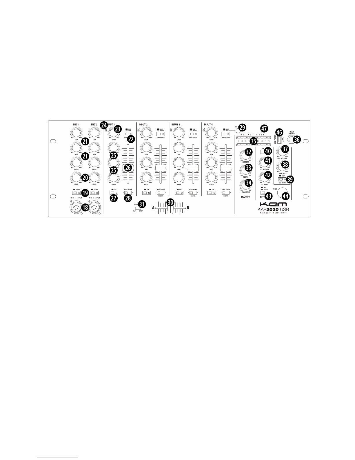
31. Crossfader Curve switch. Allows the transition characteristic of the crossfader between the X and Y signal
to be switches between smooth a flat and steep mixing curve.
32. Output level control. Determines the main output level present at outputs (3) and (4).
33. Booth level control. Determines the booth output level present at output (8).
34. Talkover control. This control allows to set the amount of damping applied to the stereo music signal when
speaking into a microphone connected to either the MIC1 or MIC2 input. The threshold level from which on
this damping is activated is set by the rear panel control (16).
35. Output level meter. Displays the output level at outputs (3) and (4).
36. Headphones output. A ¼” jack 6.35mm connector to connect a headphone. Turn the CUE volume (37) down
before plugging in any headphones.
37. CUE volume. Determines the signal volume at the headphone output (36). Always set this control to
minimum before putting on headphones, as sudden high-volume impact may damage your ears. See further
health advice below.
38. CUE Mix control. If the CUE mode (39) is set to “BLEND”, the headphone signal can be a mix of the main
output and the input(s) assigned to the CUE bus by means of switches (27). This control determines the mix
ratio between the main and the CUE signal.
39. CUE Mode switch. This control offers two pre-listening modes: (A) Split. In this mode, the master signal
appears on one ear cup of the headphones, the CUE signal on the other ear cup. (B) Blend. In this mode,
main and CUE signal are mixed with adjustable ratio by means of control (38). A LED indicates the pressed
position.
40. Effects PFL switch. Allows to pre-listen to the generated effect without the effect being activated by (44).
41. Effects Return control. Controls the level of the signal coming back from the external effects processor
through the respective connector (10).
42. Effects Send control. Controls the level of the signal being sent to the external effects processor through
the respective connector (10).
43. Effects Source switch. Decides whether the Mic or the Master signal is sent to the external effects processor
as an effects source.
44. Effects on/off switch. Activates the effect from FX Return (10). Once the effect is active, this switch is
backlit.
45. USB power socket. This socket provides 5V DC at a maximum of 500mA on a USD type A socket. Please
note (a) this is NOT a data connection, and simply designed to provide power to a USB powered device, like
an MP3 player. This connection can NOT be used to replay music (b) the maximum power is 500mA, this
socket is hence NOT suitable to provide power to tablet PC’s or mobile internet devices. Exceeding the
maximum 500mA power may result in damage of the internal transformer and subsequently failure of the
whole mixer. Accordingly, please check power consumption of any device you intend to connect and make
sure to not exceed 500mA.
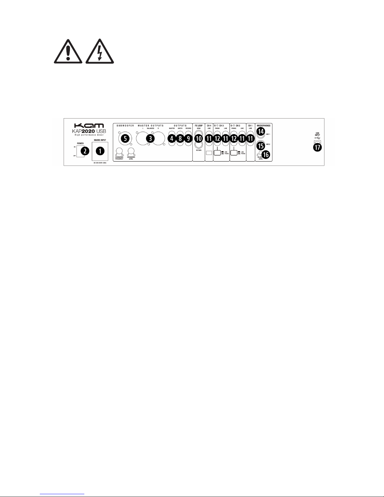
46. Power LED. Indicates whether the unit is switched on or off.
Connections
For connecting this unit to AC mains, please note:
•Check whether the AC mains voltage and frequency is the same as this product is specified for AC220-250V~
50Hz if the specified voltage or your AC plug does not match the local conditions, do NOT plug the AC cord
into the wall outlet and contact you dealer immediately.
•Do not operate this unit without the line cord earth ground connected. To do so may increase the risk of
electric shock and increase line cord conducted emissions.
For making audio signal connections, always remember that good and reliable connections are a basic
requirement for good sound and reliable operation. Bad soldering of cables can result in intermittent audio signals
or temporarily lost ground connections, hence always use good cables. In case of doubt about making proper
connections, please see check the standard pin assignments required for proper operation in the appendix of this
manual.
It is also essential that high-gain inputs are terminated properly to avoid excess noise contribution. Specifically, this
applies to the PHONO inputs. If these inputs are not used and the sensitivity is switched to “PHONO”, the inputs
shall be terminated with the supplied termination plugs (as factory-inserted at delivery).

Powering up
Following a proper power-up sequence protects your equipment – specifically speakers – and your ears. Follow
the below procedure:
•Turn down all output volume controls of any equipment in your audio system.
•Switch on your audio sources first (Turntables, CD Players, PC’s with soundcards, Tape decks, etc.)
•Switch on the audio mixer
•Switch on any audio processor between the mixer and the amplifier(s) [if any].
•Switch on the amplifier(s).
•Turn up the audio level on your sources if such controls are provided.
•Set the audio output of your mixer to a low level.
•Set the audio output of any audio processor between the mixer and the amplifier(s) to a medium level [if any
such processors].
•Turn up the volume controls of your amplifier(s) slowly.
•Make adjustments to all volume settings as needed.
For switching off, follow the reverse sequence – always switch off your amplifier(s) first, then any processors
between mixer and amplifier(s), then the mixer, then the sources.
Operation
Apart from using good equipment, good sound comes from using it correctly. Level setting mistakes are one of the
common reasons why even good equipment may not perform as desired. For setting levels, please be reminded
that two guidelines need to be followed:
•Avoid distortion by leaving some headroom. Never overrun any audio-equipment’s inputs. Level meters and
displays allow you to make sure that signals do not enter critical levels.
•Avoid unnecessary amplification by using as little attenuation as possible. For example, if you turn down the
input gain of a mixer to minimum, and then increase the main output of the mixer to maximum to drive your
amplifier properly, you will create unnecessary noise, as you first dispose of some already existing signal
level, and then later apply amplification (tainted with noise) to make it up.
Obviously, these two requirements are marking a levelling window that the operator must match to achieve a good
sound with as little distortion and noise as possible.
DANGER: Excessive volume levels on headphones or other sound systems may cause
hearing damage. Always turn the volume control to minimum when you switch the unit on,
and do not exceed healthy listening levels.
Maintenance and warranty
While we have chosen the best components to make this product is as rugged and reliable as possible, some
parts in audio products (potentiometers, faders, switches) are subject to wear which is a matter of usage and not of
time. While providing a one year warranty on the product, we have to limit the warranty on electro-mechanical
parts to 90 days from the date of purchase. In many cases, malfunction of electro-mechanical parts occurs due to
dust contamination, which may require cleaning of such parts. As the inside of such parts is not accessible, a
common practice is to use cleaning fluids in the shape of sprays. Please be reminded that many of such fluids
contain chemicals which may wash away the dust but at the same time corrode or damage contact surface and
may cause cosmetic damage to other parts. We hence explicitly exclude any claims for exchange of damaged part
due to mechanical or chemical impact.
Further to that, this unit does not need regular maintenance. The internal electronics are protected by a 5x20mm
fuse. The fuse can be accessed by the small drawer in the mains inlet. To change the fuse, unplug the power cord
first, pull out the fuse drawer and replace the fuse ONLY with a fuse of SAME voltage and rating. If the fuse blows
again after replacement, hand over the unit to qualified service personnel.

Technical Data
Mains Input EU version…...……………………………......……………AC220-250V~ 50Hz
Power consumption…………………………………………………………….……max. 18W
Fuse …………………………………………………..250v ac 500ma 20mm slow blow fuse
Frequency response…………………………….……………………..20Hz-20kHz ±1.0 dBu
S/N………………………………………………………………...……………………….>77dB
THD+N………………………………………………………… ……………..< 0.07% @ 1kHz
Dimensions…...…………………..….. W 254×H178x D 104mm (85mm mounting depth)
Weight ……………………………………………………………………………………..3.2 kg
Standards
This product complies with the following standards:
EU safety...........................................................................................EN 60065:2001 +A1
EU EMC................................................................... EN55103-1:1997, EN55103-2: 1997
US safety ………….…………..………………………………………………………UL60065
US EMC………………………..…………………………………………………..FCC Part 15
This product meets both the EMC Directive 2004/108/EC and the Low Voltage Directive 2006/95/EC.
Table of contents
Other KAM Music Mixer manuals