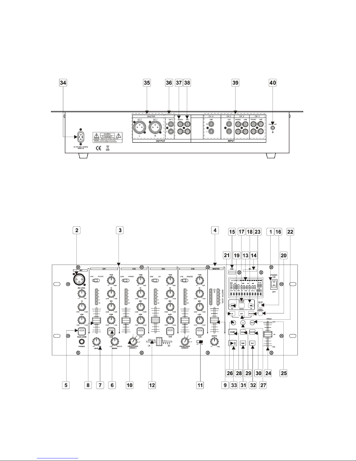
KAM KAP1200 USB User manual

KAP1200 USB
19 inch 5 channel mixer including USB & SD playback
9 input: 2 phono + 4 line + 1 mic + USB/SD
USB/SD select switch
Folder or track search / Loop and re-loop
Single or continuous playback
+/- 16% pitch control / Pitch bend
Brake and reverse effect / Manual BPM
Cue and Play controls
XLR front panel mic inputs
Talkover switch
Channel gain controls
2 band mic EQ / 3 band channel EQ
5 point LED master and PFL meters
Fader master level control / Dedicated booth output level control
Smooth 50mm channel faders / Assignable crossfader
Record outputs / 2 Master outputs (balanced/unbalanced)
M A N U A L V E R S I O N 1 . 0
07.06.10
For the latest instruction manual updates and information on the entire Kam range visit:
www.kam.co.uk
Kam products are manufactured by: Lamba plc, Unit 1, Southfields Road, Dunstable, Bedfordshire, United Kingdom LU6 3EJ
Telephone: (+44) (0)1582 690600 • Fax: (+44) (0)1582 690400 • Email: [email protected] • Web: www.lambaplc.com
If this product is ever no longer functional please take it to a recycling plant for environmentally friendly disposal.
Due to continuous product development, specifications and appearance are subject to change.
© Copyright Lamba plc 2010. E&OE.

Thank you for purchasing this product, we are sure that it will serve you for many years to come.
To optimise the performance of this product, please read these operating instructions carefully to familiarise yourself with the
basic operations of this unit. After you have read the instructions, please retain them for future reference.
This unit has been tested at the factory before being shipped to you.
To prevent or reduce the risk of electrical shock or fire, do not expose the unit to rain or moisture. To prevent a fire hazard, do not
expose the unit to any naked flame sources. Unplug this apparatus during lightning storms or if it is unlikely to be used for long
periods of time.
When installing the unit, please ensure you leave enough space around the unit for ventilation. Slots and openings in the unit are
provided for ventilation to ensure reliable operation of the product and to protect it from overheating. To prevent fire hazard, the
openings should never be blocked or covered.
Always handle the power cable by the plug. Never pull out the plug by pulling on the cable. Never touch the power cable when
your hands are wet as this could cause an electric shock. Do not tie a knot in the cable. The power cable should be placed such
that it is not likely to be stepped on. A damaged power cable can cause a fire or give you an electrical shock. Check
the power cord periodicaly, if you ever find that it is damaged, replace it before using the unit again. Contact your retailer for a
replacement.
The voltage of the available power supply differs according to country or region. Be sure that the power supply voltage of the area
where this unit is to be used meets the required written on the unit.
The lightning flash symbol inside a triangle is intended to alert the user to the presence high voltage within the unit’s
enclosure that may be of sufficient power to constitute a risk of electrical shock to persons.
Caution: to prevent the risk of electric shock, do not attempt to open the unit. No user-serviceable parts inside. Refer all
servicing to qualified service personnel.
The exclamation mark inside a triangle is intended to alert the user to the presence of important operating and
maintenance instructions in the literature accompanying the appliance.
Any modification carried out on the unit may invalidate the unit’s warranty.
If applicable, only use the stand, tripod or bracket specified or sold with the apparatus.
Select the installation location of your unit carefully. Avoid placing it in direct sunlight or locations subject to vibration and
excessive dust. Do not use the unit where there are extremes in temperature (below 41ºF / 5ºC or exceeding 95ºF / 35ºC).
Unpacking and safety: Please unpack your new product carefully, your new product should reach you in perfect condition. Please
check that no damage has occurred during transit. If any damage is found, do not operate your unit. Please contact the retailer
you purchased it from immediately. If there is any damage to the mains cable do not use the device. Always disconnect the unit
from the mains supply when carrying out any servicing or cleaning of the unit.
The serial number for this equipment should be located on the rear or underside of the unit. Please make a note of this number as
you will need it for your warranty, it is a good idea to keep a copy of the serial number for your own records.

Rear panel
Front panel

1. Power - Main power on/off switch.
2. Microphone section
Input socket via XLR.
Mic level - Adjusts the volume of the microphone.
High - Adjusts the treble tone control of the microphone.
Low - Adjusts the bass level of the microphone.
3. Channel section - Input selector, controls knobs & level meters Ch1 to Ch4.
Channel input selector switches select the input source to be assigned to the channel.
Ch1 switches between Line & Phono.
Ch2 switches between Line & Phono.
Ch3 switches between Line & CD.
Ch4 switches between Line & USB/SD.
Trim - Adjusts the input signal level.
High - Adjusts the treble level, the centre position is flat. Turn clockwise to increase to +12dB turn anti-clockwise to
reduce by -24dB.
Mid - Adjusts the mid level, the centre position is flat. Turn clockwise to increase to +12dB turn anti-clockwise to reduce
by -24dB.
Low - Adjusts the bass level, the centre position is flat. Turn clockwise to increase to +12dB turn anti-clockwise to
reduce by -24dB.
Peak level meter - The display holds the peak level for 2 seconds, display range -10dB - +6dB.
The peak level is determined by the position of the line fader.
4. Master level section - The master level slider controls the overall volume of the main output.
The master level led display shows the main output level, and the display peak is held for 2 seconds.
Display range - 5dB to +7dB.
5. Talk over - Press this switch and the main output level will drop by approx 14dB. This does not affect the microphone
level output (the button will illuminate when this function is in use) pressing the button again will restore the main output
volume again. Caution: using this switch will cause a sudden and major change to the master output level.
6. Headphone cue - Using this button will select which channel (1-4 can be monitored via the headphones, the button will
illuminate to show selected channel press again to de-select. Multiple channels can be monitored at the same time.
7. Headphone section - Connect headphones via the ¼ inch jack socket.
Volume control - This adjusts the volume level of the headphones.
Mixing control - This control when turned fully clockwise monitors the master output. When turned fully anticlockwise
this monitors the cue level of the selected channel, adjusting the position of this control can mix the cue & master
output, both can be monitored at the same time.
8. Channel fader volume - Controls the output level for each channel (1-4).
9. Master fader level - This controls the main master output level of the mixer.
10. Crossfade assign - A & B this assigns which channels are to be used with the cross fader, select between Ch1-4 on A
and Ch1-4 on B the cross fader will mix between the 2 selected channels.
11. Crossfade curve - There are 2 options of how the cross fader mixer / dips.
12. Crossfader - This mixes the output of the channels selected (example when fully left ch1 will play, when fully right
channel 2 will play, when central both channels can be heard through the main output.

13. Display
A. SD card/USB indicator
B. Track number - This displays the position, number of track of the USB or SD card, which is playing.
C. Operating mode - These indicate whether the USB or SD card player is in playing or paused mode.
D. Time mode indicators
Elapsed: Played time of the selected track.
Total remaining: Total remaining play time of the USB or SD card.
Remaining: Remaining play time of the selected track.
E. Minute, second and frame displays
These displays show the current time, the value changes depending on the time mode selected.
F. Time bar indicator - This is a graphical representation of the “minute, second and frame displays”(c).
G. BPM - Display the BPM of the track displayed.
H. Folder display
I. Program Indicator - This indicates the player is in programme mode.
J. Play mode indicators
Single: The USB or SD card player is in single mode.
Continue: The USB or SD card is in continue mode.
K. Loop indicator - This indicates the USB or SD card player is currently playing in a preset loop.
L. Repeat indicator
Repeat1: The USB or SD card player is playing the selected track repeatedly.
Repeat all: The USB or SD card player is playing the entire USB or SD card repeatedly.
M. Pitch indicator - When the pitch display, the pitch slider just have function.
N. Pitch display - This indicates the playback speed (pitch), from 16% to +16%.
O. ID3 communication display
P. Cue indicator - This indicates a new cue is set.
14. SD slot - Insert the SD card.
15. USB port - Insert USB stick.
16. SD/USB button - Use to select SD or USB input.
17. Folder/track - Press the button & when the button is illuminated it is in folder mode. Press the +/-buttons to select a
folder. When not illuminated it is in track mode, press the +/- buttons to select the track.
18. In folder mode pressing this button will move forward to the next folder, in track mode will move forward to the next
track (holding the button down will increase the speed of the track/folder skip).
19. In folder mode pressing this button will move backwards to the previous folder, in track mode will move backwards to
the previous track (holding the button down will increase the speed of the track/folder skip).
20. Single/cont - Press this button to switch between single/ continuous mode, in single mode it will play one track and
then stop. In continuous mode it will all tracks then stop.
21. Loop - In button will start the loop position and loop will be shown in the display.
22. Loop - Out button will determine the end of the loop, and the loop will play, press the out button again to stop the loop.
23. Re-loop - This button will restart the saved loop.
24. Pitch fader - This will increase or decrease the speed of the track.
25. Pitch button - When illuminated the pitch fader function is available.
26. Pitch bend + While pressed this will speed the track up and when released the speed will return to the normal position.
27. Pitch bend - While pressed this will slow the track down and when released the speed will return to the normal position.
28. Cue - In pause mode use the search buttons to find an exact cue point. Press play to set the cue position. Now
pressing cue, the track will return to the start of the cue point set.

29. Brake - When the button is illuminated a brake effect is activated, pressing the play button while the track is playing will
slowly bring the track to a stop. Pressing the play button in pause mode will start the track slowly the will climb to correct
speed.
30. Reverse - When this button is illuminated the track will play backwards.
31. Time - This button will toggle between time elapsed and time remaining, this will be displayed in the screen.
32. Tap - Press the tap button continuously to the beat of the music to activate the manual BPM counter, this will determine
the speed of the track and give a visual BPM (beats per minute) value in the display.
33. Play/pause - This button will play or pause the track.
34. Mains power cable input
35. Balanced outputs - Connect balanced XLR leads to the amp. Controlled by master volume slider.
36. RCA master outputs - Connect RCA/phono leads to the amp. Controlled by master volume.
37. Booth - Connect RCA/phono leads to the amp. Controlled by booth volume.
38. Rec - Connect RCA/phono leads to a tape deck or recording device.
39. Source inputs - Connect either phono or line level inputs here. Please note phono is for turntables only, these must not
be connected to a line level source input. Likewise line level source must not be connected to phono inputs.
40. Earth - Use this tag to connect the earth tag lead on turntables to reduce audio hum. This is for turntable earth only and
should not be used as a main earth grounding point.
Specifications
Input terminal (input level/impedance)
CD/line 300mV/22k
Phono 5mV/47k
Main mic 5mV/3k
Mic 5mV/3k
Frequency characteristics
CD/line/phono/mic 20Hz to 20kHz
SN ratio
CD/line 86dB (with effects off)
Phono 76dB
Mic 69dB
Total harmonic distortion rate
CD/line/phono 76dB
Cross talk Over 70dB
Channel equalizer
Hi +12dB, -24dB (13kHz)
Mid +12dB, -24dB (1kHz)
Low +12dB, -24dB (70Hz)
Microphone equalizer
Hi +12dB, -12dB (10kHz)
Mid +12dB, -12dB (1kHz)
Low +12dB, -12dB (100Hz)
Power supply voltage AC100-240v (10kHz)
Power consumption 20w
Operating temperature +5 c to +35 c
Operating humidity 5% to 85%
Table of contents
Other KAM Music Mixer manuals