K&M Burkhard Reuter RLA4GS User manual

Specifications
and Operator Manual of antenna
RLA4G/GS
Version: 1.4
Created: 20.06.2020
Konstruktion & Musterbau Burkhard Reuter Ziegelstraße 54 06862 Dessau-Roßlau

Specifications RLAG
Single loop dimensions: About 500 mm x 500 mm
Amplifier dimensions (W x H x D): 140 mm x 60 mm x 120 mm (without connectors)
Frequency range: 50 kHz … 30 MHz
Average noise level (without loops): <= -145 dBm/Hz (at 10 MHz)
IP3: >= +32 dBm (2x -6 dBm measuring tone at 10 MHz)
IP2: >= +80 dBm (10.0 MHz + 10.2 MHz -6 dBm measuring tone, 0.2
MHz measured difference tone)
Maximum output voltage: >= 1 Veff, 1 dB compression
Supply via HF cable: +6.0 V … +13.8 V, maximum +14.4 V!
Power supply: max. 80 mA
HF output: BNC 50 ohm
Weight: <= 1.5 kg
Environmental conditions: -20 ... +40 °C ambient temperature, <=100 % rel. humidity
IP65 (with connected loops and connection cable)
Compliance: CE according to DIN EN 55013, EN 55020, EN 60065
RoHS / WEEE Directive, ear-Reg. 27676700
Specifications RLAGS (only deviating from 4G)
Single loop dimensions: Diameter horizontal approx. 770 mm
Height incl. housing approx. 690 mm
Frequency range: 20 kHz … 30 MHz
Weight: <= 2.0 kg
Changes are reserved in the course of technical development!
VERSION DATE NAME K & M Burkhard Reuter Page 2 of 8
1.4 24.11.2021 B. Reuter RLA4G/GS

Safety precautions
Please always keep the following safety precautions in mind!
Never connect the device to any other voltage than indicated in the specifications. Under no
circumstances should the device come into contact with the mains voltage of 230 V ~!
It is essential to observe the lightning protection regulations for the outdoor operation of
electrotechnical systems! The antenna must be properly equipped with lightning protection when
installed outside a protected area (e.g. house). The HF bypass must be equipped with overvoltage
protection. In case of lightning hazard, immediately take the antenna out of operation and
disconnect it safely from other devices (remove HF connection)!
Observe the permitted temperature range for starting up the device! Do not switch the device on or
off again if this range is exceeded or fallen below!
When disassembled, always provide a safe placement on a flat, straight and solid base of
sufficient carrying capacity! The antenna is intended for outdoor installation on firmly anchored
components (mast, beams, roof, wall, ...). Observe the permissible wind load! Always transport the
device either in solid cardboard or wooden boxes (e.g. the delivery packaging), or transport it by
firmly gripping the amplifier housing! The device may cause injury in the event of a fall due to its
own weight!
Never expose the device to mechanical stress due to impact, pressure, vibration or shock which
exceed a normal level. Never carry or attach the antenna to the antenna elements.
Never open housings and never move screw connections on the housings, unless expressly
requested in the operator manual. This can lead to damage to seals or components connected to
the screw connections.
If you notice any damage to the device, immediately take it out of operation (remove power
supply)! If necessary, send it to the supplier for repairs.
Would you like to dispose the device due to damage or no more usability, send it back to the
supplier or return it to your local waste collection center. Never dispose of the appliance
elsewhere, such as household waste. It pollutes our environment!
The nameplate of the RLA4G is located inside the amplifier housing. It is visible after removing the
base plate.
VERSION DATE NAME K & M Burkhard Reuter Page 3 of 8
1.4 24.11.2021 B. Reuter RLA4G/GS

Operator Manual
The RLA4G is a cross loop receiving antenna for fixed outdoor installation. It operates broadband as a
non-tuned active antenna with an integrated amplifier. The power is supplied via the HF cable. The two
loops consist of coaxial cables for the symmetrical control of two differential current amplifiers with a low-
impedance input. The utilization of the latest components in the two amplifier branches guarantees very
low intrinsic noise values and high intermodulation resistance. The two reception loops are arranged at an
angle of 90° to one another. By adjusting the amplifiers, an electronic rotation of the receiving direction is
possible. The outer jacket of the antenna elements is grounded on the amplifier housing and shields the
actual loops (inner conductor) against interference radiation.
The amplifier is installed in a sealed aluminum housing. The HF currents of the antenna elements are lead
waterproof into the housing via RP-TNC coaxial connectors. The HF derivation to the RX takes place via a
sealed TNC housing bushing. The bottom of the housing has tabs with holes for screwing the antenna
onto flat construction elements (beams, straight roof surface, mast head with flat sheet metal or similar).
In addition to the HF connections of the amplifier, the antenna elements are also attached to a connection
housing (common ground point, HF voltage and current zero point). It is connected to the amplifier housing
via a connection rod. This means that all metal parts are at the same low-impedance potential and can be
grounded via the amplifier housing (lightning protection).
If lightning protection is not necessary (observe the relevant regulations!), grounding is not necessary to
operate the antenna. The connection to the receiver via the antenna cable is sufficient. However,
grounding can be useful to derive interference. On the other hand, it can also cause faults if the grounding
point is chosen unfavorably (e.g. equipotential bonding of the power supply, which often leads to high
interference currents).
So-called ground loops can occur if the antenna is (supposed to be) grounded (multiple, spatially spaced
ground connections, e.g. lightning rods and antenna cables), which can act as a reception loop. In this
case, further measures are necessary, such as choking the antenna cable (e.g. winding it onto a ferrite
toroid) or special grounding of the receiver end or the receiver. These measures are heavily dependent on
the environment and the additional wiring of your electronics and their necessity / effectiveness must be
determined empirically.
Power supply to the RLA4G is only possible via the HF cable ("remote power supply"). Any remote supply
device that can be looped into the antenna cable and that can supply the required voltages and currents
(see technical data) is suitable for this. The fed voltage’s level can be modulated with a data signal in order
to electronically control the direction of reception (for example using control units RSW2 or RSW3, see
description of these devices).
The RLA4G must be assembled vertically with the connection housing facing up. Slight deviations from the
vertical are permitted. The reception diagram is then eight-shaped in the horizontal (bidirectional with 2
wide reception lobes and two sharp zeros). Without a control unit (remote supply with constant voltage),
the main reception direction is approximately transverse to the direction of the connection socket for the
antenna cable (the zeros are approximately in the axial direction of the socket).
This direction also corresponds to the 0° setting on the control unit. The RLA4G is not suitable for direction
finding. The absolute deviation of the setting compared to the actual reception direction can be several
10°s. The purpose of the electronic rotatability is the orientation towards maximum suppression of
interference signals, as well as the reception of useful signals, which are at the zero position for antennas
with a fixed reception direction without the possibility of rotation.
If the degree display on the control unit should approximately correspond to the actual cardinal direction
(max. reception or zero point), the antenna must be "northed" once during assembly.
VERSION DATE NAME K & M Burkhard Reuter Page 4 of 8
1.4 24.11.2021 B. Reuter RLA4G/GS

Assembly of the antenna RLA4G
The RLA4G is supplied with removed antenna elements.
Component set for an antenna RLA4G
The component set consists of the following parts:
•4 pieces of antenna elements (each half of a loop), coaxial cable LMR-400 with TNC connectors of
reversed polarity (RP-TNC).
•Node (connection) housing made of plastic with 4 RP-TNC sockets.
•Amplifier housing made of bright aluminum with 4 RP-TNC sockets and normal TNC socket for the
antenna cable.
•Stainless steel connecting rod with a M5 nut screwed on each end.
All parts are made of weatherproof material (resistant to UV radiation and moisture) and are IP65 dust and
waterproof after proper assembly. The amplifier inside the aluminum housing is designed for a wide
temperature range (no electrolytic capacitors, components with an extended temperature range). All
components, with the exception of the coaxial connector for connecting the TNC socket for the antenna
cable, are arranged in an SMD version on a circuit board and sealed with synthetic resin.
The amplifier housing is bare metal in order to achieve a high reflectivity against solar radiation. This
keeps the amplifier from heating up as much as possible on hot summer days. The housing consists of a
body in which all parts are mounted and a screwed-on base plate with an inserted seal. There are tabs on
the floor panel for attachment to any support elements (mast heads, beams, roof surfaces, ...). Fastening
must be carried out using suitable countersunk screws (wood, self-tapping or threaded countersunk
screws of 4 mm in diameter).
Caution! When screwing the housing on, no forces may act on the tabs or the base plate (no "warping").
The mounting surface must be absolutely flat and level! If necessary, suitable supplements must be placed
to compensate.
There are 4 small holes in the bottom plate near the corners. They serve to equalize the pressure in the
housing in the event of major temperature changes, as well as to drain off any condensation that may have
VERSION DATE NAME K & M Burkhard Reuter Page 5 of 8
1.4 24.11.2021 B. Reuter RLA4G/GS

formed. At least one of the holes must be kept clear when mounting the antenna to a bracket. If the
antenna is not absolutely horizontal, this must be the hole furthest down (this is where condensation
collects).
Holes in the bottom plate provide ventilation and drainage
The assembly of the dismantled antenna is quite simple and should be carried out in the following order
(disassembly in reverse):
•Screw the connecting rod into the amplifier housing. There is an M5 spacer bolt on the top of the
housing, into which the threaded pin at the end of the rod fits. An M5 nut should already be
screwed onto the threaded pin, which must be screwed onto the rod as far as it will go (otherwise
screw on the nut so far). Screw the rod into the spacer of the amplifier housing until it stops
against the nut. Caution! Tighten only slightly loosely to a maximum hand-tight and hold it
straight, do not exert any torque or shear force on the spacer bolts!
•Similarly, screw the node housing onto the other end of the rod. Again, pay attention to the
presence and full screwing of the nut and the maximum light tightening.
•Align both housings (turn them against each other) so that the sides are parallel to each other. The
connectors on each side of both housings must point in the same direction (slight twisting by 1 - 2
degrees does no harm). Caution! The connecting rod must not be screwed firmly into the spacer
bolts on either side! Only turn to the right (clockwise when viewed from above) until the screw
connections are at most hand-tight. For final alignment of the housings, (loosely) turn to the left.
•Counter the nuts on the threaded rod against the spacer bolts on both housings. To do this, hold
the spacer bolts with a size 8 open-end wrench and use another wrench to turn the nut firmly
against the bolt. Never grip the housing during assembly! The spacer bolts are sealed on the
housing. If they are turned against the housing, the seal will be destroyed and moisture could
penetrate! Make sure that the housings remain parallel to each other.
•Screw on the antenna elements. The cables are already approximately semicircular, so that they
fit onto the sockets on either side of both housings without tilting. Bend a little if necessary.
Despite their relatively large diameter, the cables are easily bendable.
•Caution! Never bend them sharply, especially not at the connectors! It is best to screw one side
firmly onto a housing and then shape the cable so that the plug on the other side can be screwed
straight and easily onto the socket on the housing.
•Screw on the antenna cable. The cable to the receiver must have a standard TNC connector (not
reversed as with the antenna elements) at the antenna end. At the other end, a connector
VERSION DATE NAME K & M Burkhard Reuter Page 6 of 8
1.4 24.11.2021 B. Reuter RLA4G/GS

corresponding to the RX input is required (if an RSW control unit is used, a BNC connector).
Important notes: The TNC fittings should be tightened securely to ensure watertightness. Normally,
manual force should be sufficient (always ensure axial alignment / easy screwability without tilting the
connector!). If the force is too low (children, dainty adults, incomplete usability of the hands, ...), pliers can
be carefully used for help. However, excessive force must never be exerted, as this could damage the
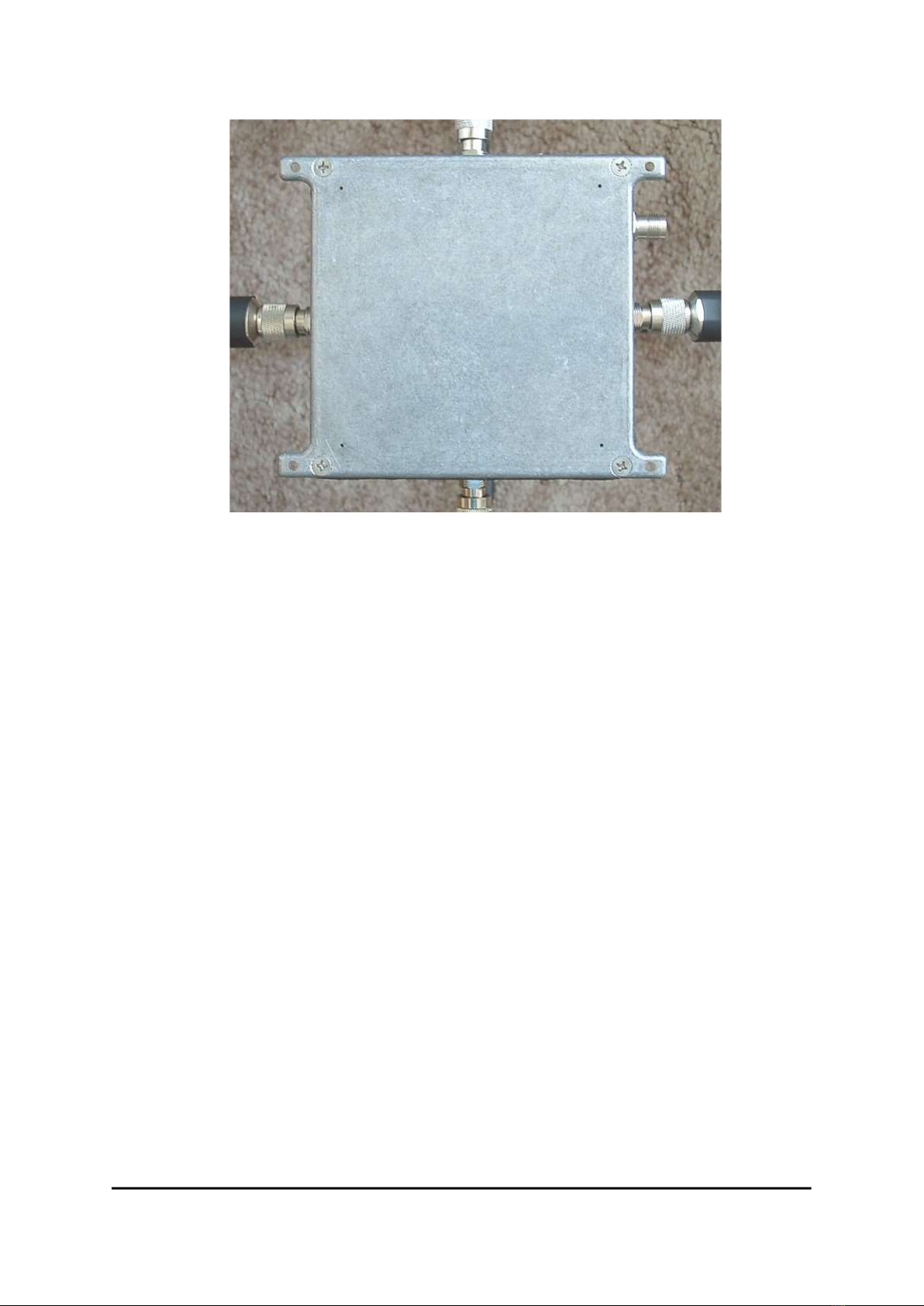
seals or even the thread of the connector! Also, the sockets in the housing must not be twisted, because
otherwise their sealing can be destroyed and the internal connections can tear off!
Never turn TNC connectors against each other! Only the union nut may be turned, never the plug
against the socket!
Reason: In the plug (the connector on the cable, in RP-TNC this is actually a socket) has spring elements
slotted in the axial direction. These press firmly against the corresponding contact surface of the socket
when the plug is inserted. If the plug is rotated in the process, the sharp-edged slots literally mill off the
contact surface of the socket.
So never, for example, apply the plug only slightly, so that the union nut just attaches, and then turn the
whole cable with plug and union nut on the socket. This is relatively easy because you can use the cable
as a lever. But it damages the spring elements and the socket!
Correct: Press the plug firmly onto the socket (push axially only, i.e. in the longitudinal direction!) until the
threads of the union nut and socket are against each other. Then unscrew the nut as far as easily
possible. Then push the plug on further, again turn the nut a little further and continue alternately in this
way until no further pushing on / turning of the nut is possible.
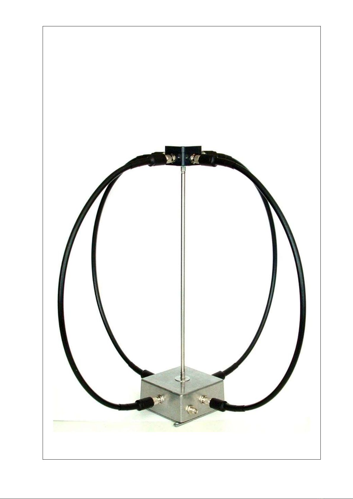
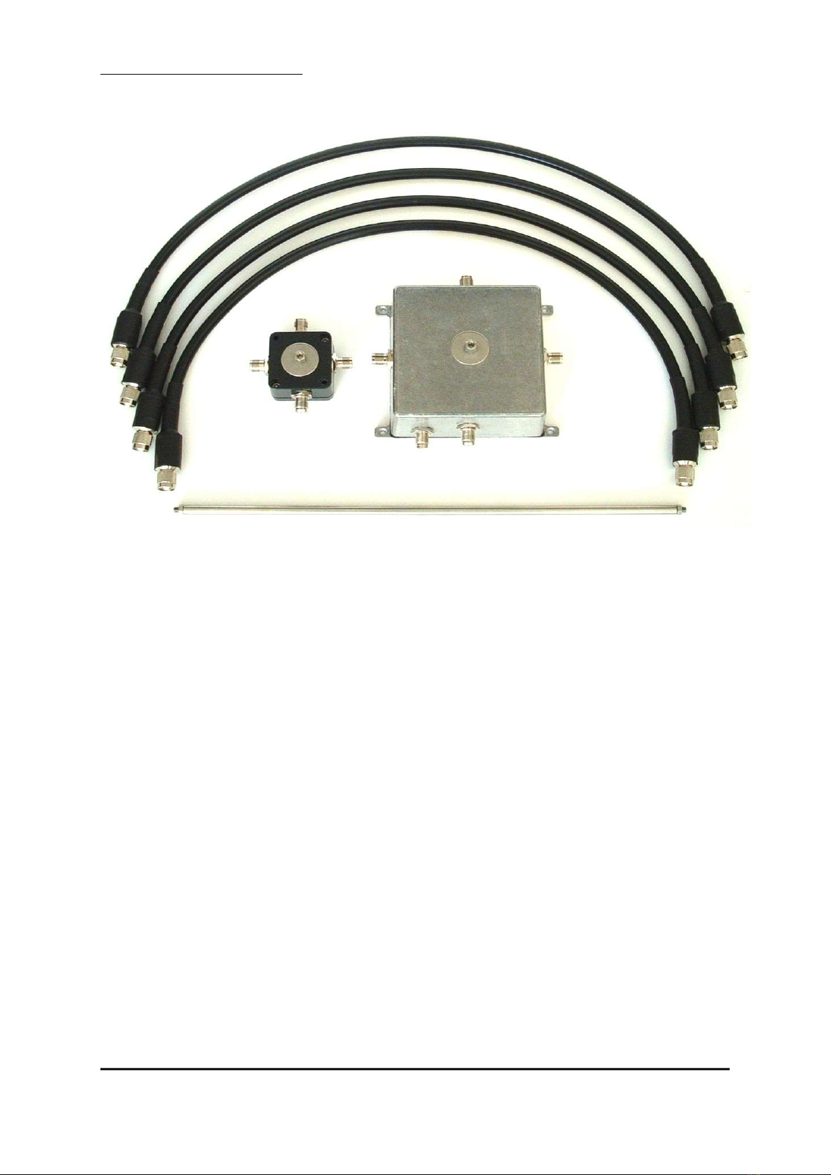
The most sensible thing to do with the RLA4G is to start by lightly screwing the cables to the top connector
housing and letting them hang straight down near the sockets on the amplifier housing. Then plug on there
as described and screw on tightly. Then tighten completely at the top. In this way, rotation of the plugs in
the sockets can be largely avoided.
After assembly, the shape of the coaxial cable can be straightened out a bit. Usually, the loops
automatically have a slightly "wobbly" shape because the upper housing is smaller than the amplifier
housing. Also, the cables are rarely exactly straight. This can be easily recognized by looking at the
connecting rod and, if necessary, straightening the cable accordingly. However, all these are purely
aesthetic flaws, the function of the antenna is not affected.
If the TNC connectors are dismantled and reassembled frequently, they should only be screwed on far
enough to ensure stable contact (protection of the threads). The connectors are made of brass, which likes
to jam a bit with wear. It is then helpful to use a small amount of acid-free grease (e.g. silicone grease).
If the antenna is likely to never be dismantled again, sealing the connectors by wrapping them with self-
vulcanizing sealing tape is highly recommended. Caution, pay attention to UV-stable material!
In case of strong wind load, the tip of the antenna (upper part with node housing) may start moving. All
internal connections are made with flexible strand, so that these small movements are absorbed.
Nevertheless, they put a strain on all components (especially the connection to the aluminum amplifier
housing), which can lead to material fatigue over time. In this case, the tip of the antenna should be
intercepted by attaching a support to the upper screw connection of the center pole to the node housing
(e.g. thick sheet metal strip with 5 mm hole guided laterally to a pole).
VERSION DATE NAME K & M Burkhard Reuter Page 7 of 8
1.4 24.11.2021 B. Reuter RLA4G/GS

Version RLA4GS
The GS version differs from the standard G version mainly in its larger diameter. The loop elements here
consist of 1 m long 12.7 mm (1/2") coax cables. Low-attenuation "Flex" or "Superflex" cable with a shield
made of solid, corrugated copper sheet (100 % shield coverage) is utilized. This results in very high
attenuation values against interfering radiation.
The increased loop diameter enables stronger reception on low frequencies. In conjunction with the
amplifier version RLA4 from version "J" (standard in all RLA4 from November 2021) the lower cut-off
frequency drops to approx. 20 kHz. The levels in the range from 50 kHz up to the lower KW range are
approx. 3 dB higher compared to version G with lower inherent noise power.
However, the larger loop circumference also increases the self-inductance of the loops and thus causes a
reduction in antenna current at high frequencies. This is partly compensated by the much thicker inner
conductor of the cables (lower ohmic resistance, reduction of inductance with increase of conductor
diameter). Overall, the reception performance of the RLA4GS above approx. 7 MHz (40 m band) is about
the same as that of the RLA4G.
RLA4G and RLA4GS
Assembly instructions
The coaxial cables are equipped with connectors according to standard "4.3-10". These are very robust
and waterproof connectors similar to the "N" standard. There are versions with knurled screw connection
for tightening by hand (as with TNC or N) and with hexagon nut (SW 22).
When mounting the cables without tools, follow the instructions as for version G with TNC connectors.
Basically, these also apply to the hexagon nut version. However, a tighter screw connection can be
achieved here by using an appropriate tool (open-end wrench). However, the tightening of the screw
connections must only be carried out with low force (only a little more than the nuts can be tightened by
hand)!
The instructions for absorbing movements under wind load must be observed in particular!
VERSION DATE NAME K & M Burkhard Reuter Page 8 of 8
1.4 24.11.2021 B. Reuter RLA4G/GS
This manual suits for next models
1
Table of contents
Other K&M Burkhard Reuter Antenna manuals