14000 Drummersitz
»Gomezz«
- Drummersitz für den Profi: sehr stabil und standsicher
- Feinstufig in der Höhe verstellbar in 10 mm-Schritten
-von min. 475 bis max. 675 mm
- Drehbewegung des Sitzes individuell und stufenlos
-einstellbar von leicht- bis zähgängig
- Bester Sitzkomfort durch hochwertige Polsterung und
-ergonomisch geformte Sitzfläche
- Unverlierbare Parkettschoner mit hervorragender Dämpfung
- Tourtauglich: platzsparend zusammenlegbar, Gewicht: 6,1 kg
- Sitz kann mit einem Körperschallwandler oder Rückenlehne ausgestattet werden
SICHERHEITSHINWEISE WARNHINWEISE
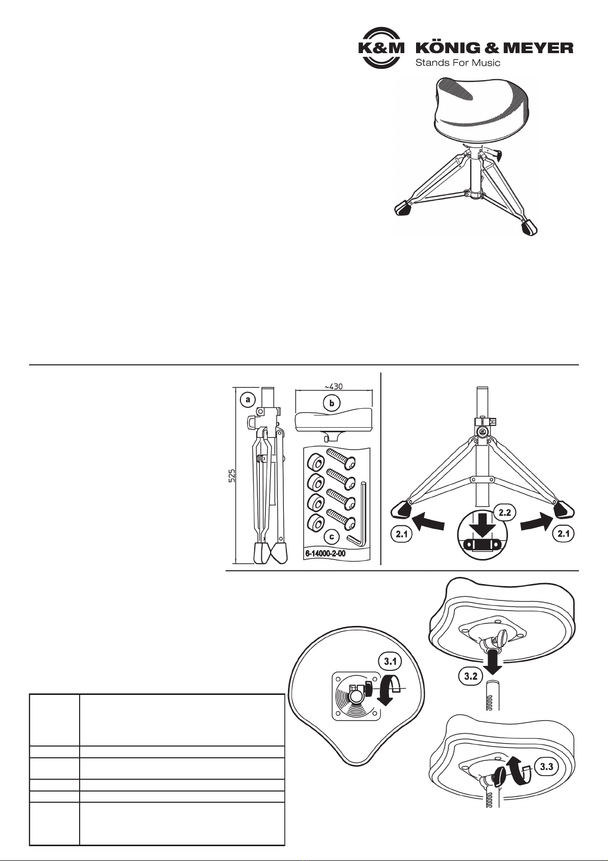
AUFSTELLANLEITUNG 1. BESTANDTEILE
3. POLSTERSITZ
2. FUSSGESTELL
- Gewarnt wird ausdrücklich vor der Benutzung als Steighilfe.
- Der Polstersitz ist mit dem Auszugrohr nicht verschraubt, sondern auf-
-gesteckt und festgeklemmt und kann sich beim Anheben evtl. lösen.
-Deshalb: Polstersitz und Auszugrohr getrennt transportieren oder
-Deshalb: Fußgestell und Sitz gleichzeitig festhalten
- Die Parkettschoner sind aus hochwertigem Material und weitestgehend
-frei von Weichmachern. Trotzdem sollte ggf. eine rutschfeste Unterlage
-unter die Füße gelegt werden, da diese auf empfindlichen Böden
-(z.B. Parkett) Spuren hinterlassen können.
1. BESTANDTEILE
Bitte Sichtprüfung vornehmen, ob alle Teile vollständig
vorhanden und soweit erkennbar in Ordnung sind.
aFußgestell,
bPolstersitz,
cZubehörbeutel: 1 - Distanzscheibe (4x),
cZubehörbeutel: 2 - Schraube M6 x 30 mm (4x),
cZubehörbeutel: 3 - Inbusschlüssel SW5
Prüfen Sie ebenfalls die Gängigkeit der beweglichen
Teile (Auszugrohr, Fußstreben, Rastknopf, Klemmhebel).
2. FUSSGESTELL
Fußgestell bitte aus Karton entnehmen.
2.1 Füße an den Parkettschonern fassen und
2.1 auseinanderziehen.
2.2 Untere Schelle bis zum Anschlag des Grundrohres
2.2 schieben.
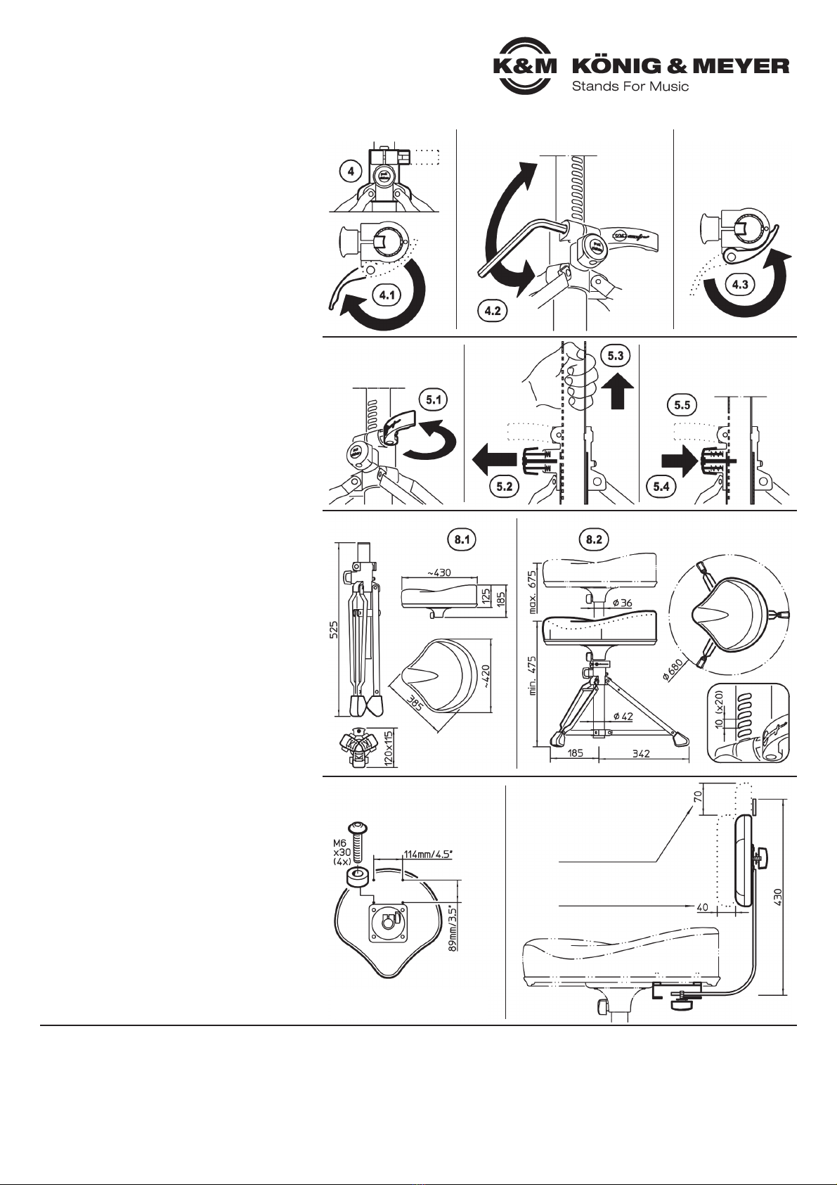
3. POLSTERSITZ
Polstersitz bitte aus Karton entnehmen
3.1 Flügelmutter an der Unterseite des Sitzes lösen.
3.2 Sitz bis zum Anschlag auf das Auszugrohr stecken.
3.3 Flügelmutter mehr oder weniger fest anziehen:
3.3 auf diese Weise kann die Drehbewegung des
3.3 Sitzpolsters von leichtgängig bis zäh eingestellt
3.3 werden (siehe Kapitel 6).
Es besteht die Möglichkeit auf der Unterseite des
Sitzes eine Rückenlehne (K&M Art-Nr. 14005) oder
einen sogenannten Körperschallwandler anzubringen
(siehe Kapitel 9. ZUBEHÖR).
Vielen Dank, dass Sie sich für dieses Produkt entschieden haben. Bitte lesen und beachten Sie vor
Aufbau und Betrieb dieses Produkts sorgfältig diese Anleitung. Sie informiert Sie über alle wichtigen
Schritte, um eine sichere Handhabung zu gewährleisten. Wir empfehlen, sie auch für den späteren
Gebrauch aufzubewahren.
KÖNIG & MEYER GmbH & Co. KG
Kiesweg 2, 97877 Wertheim, www.k-m.de
14020-019-02 Rev.09 03-80-140-00 12/20
- Max. 100 kg Tragkraft
- Auf geeigneten, tragfähigen und ebenen Untergrund achten
- Die Möglichkeit das Produkt zusammenzuklappen und zu verstellen,
-birgt Einklemmgefahren. Umsichtige und aufmerksame Handhabung bei
-Aufbau, Betrieb und Abbau sind unverzichtbar
- Der Druckknopf-Rastbolzen muss stets eingerastet sein - andernfalls
-besteht die Gefahr des ungewollten und unkontrollierten Einfahrens
- Der graue Klemmhebel muss stets geschlossen sein
- Für beste Standsicherheit werden die Füße maximal ausgebreitet:
-das ist der Fall, wenn die bewegliche Schelle 2.2 bis zum Anschlag nach
-unten geschoben wird
Material
Stahlrohre und Stahlstreben: verchromt
Schellen: PA-6 schwarz
Klemmhebel und Rastknopf: POM grau
Parkettschoner: TPE-Evoprene, schwarz
Polstersitz: Kunstlederbezug, schwarz
Tragkraft bis 100 kg
Maße Sitzhöhe: 475-675 mm, Fußkreisdurchmesser: 680 mm
Transportmaße: Sitz 430 x 420 x 185 mm
Gewicht 6,1 kg
Verpackung Einzelkarton: L x B x H 510 x 395 x 210 mm
optionales
Zubehör
Rückenlehne K&M 14005-000-02
Zur Montage sogenannter Körperschallwandler
Buttkicker®sind unterhalb des Polstersitzes vier
Gewindebuchsen M6 vorhanden
TECHNISCHE DATEN / SPEZIFIKATIONEN