GEGENERATOR STOP IN THE “AUTO” POSITIONNERATOR STOP IN THE “AUTO” POSITION
If the generator was started in the “AUTO” position, set the “POWER SWITCH” to the “OFF” position to stop
it. The generator will stop immediately, or press the emergency stop butto
MANUAL MODEMANUAL MODE
If it becomes necessary to start the generator without using the ATS automatic mode, set the ATS unit main
switch to “MANUAL”. After that you can start the generator.
BATTERYBATTERY
The ATS unit battery is charged automatically. The maximum charging current is 2A.
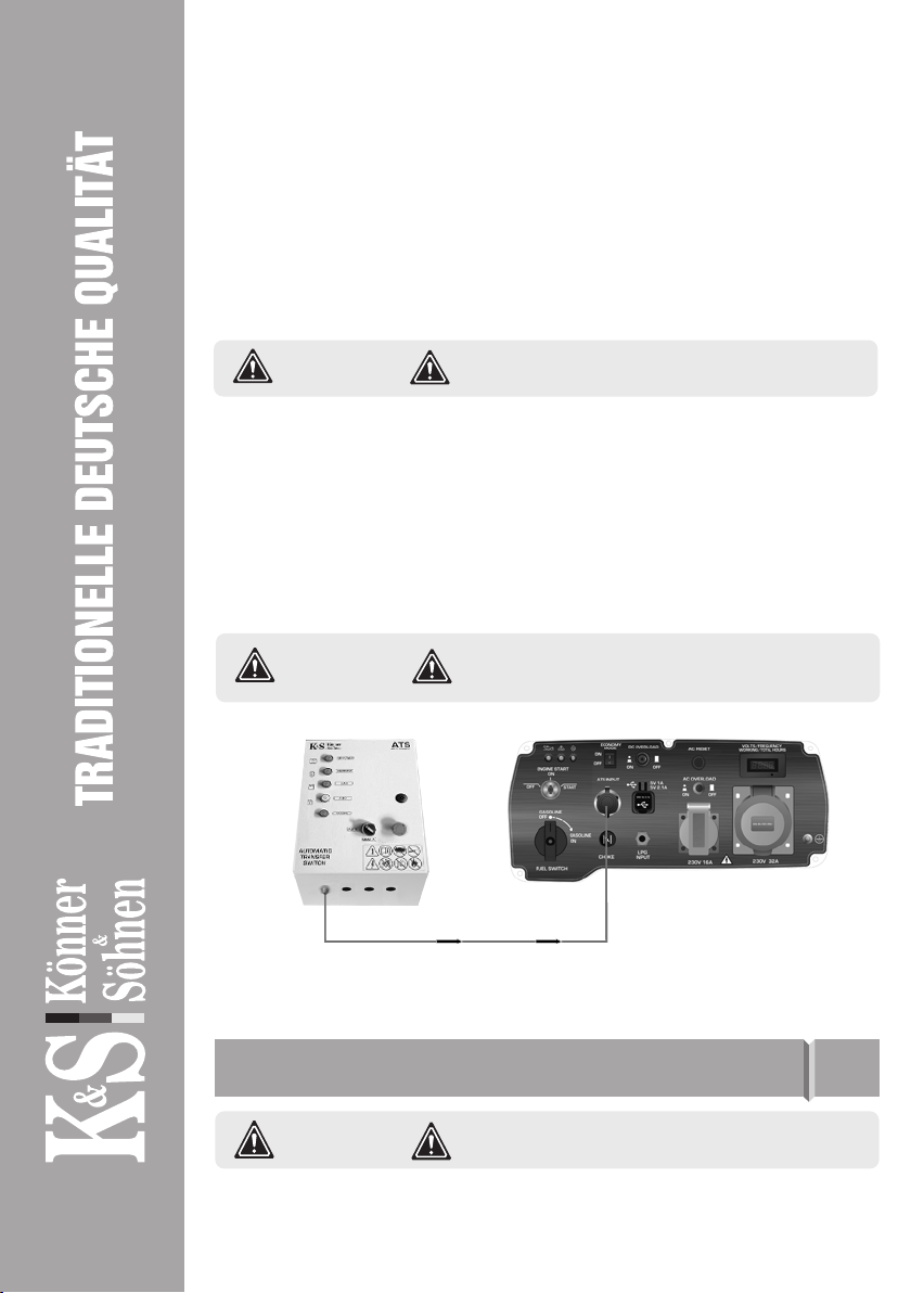
Connect the ATS unit as shown in Figs. 2-5.
AUTOMATIC MODEAUTOMATIC MODE
Turn the start key on the generator control panel to “ON” (for gasoline generators). Set the ATS unit main
switch to “AUTO”. The “AUTO” LED light indicates that the ATS system is in automatic mode.
When the main power supply is disconnected, the ATS system automatically starts the generator in 2
seconds. After 5 seconds following the generator startup, the system will switch over power consumers to
the backup power source (generator).
In case of unsuccessful startup, the ATS system attempts to start the generator three times with an interval
of 6 seconds between the attempts. If all three attempts are unsuccessful, the ATS unit will stop trying to
start the engine and signal an error.
OPERATING PROCEDURE 5
CONNECTION OF THE GENERATOR AND ATS
TO THE BUILDING POWER SUPPLY NETWORK 6
Use the control cable to connect the ATS unit to the power
generator; the generator must have a special connector
for connecting the ATS.
PLEASE NOTE!
It is forbidden to use the generator using LPG as fuel in
the mode of automatic start of ATS unit! It is dangerous
to leave the connected LPG cylinder open in the standby
mode, a gas leak can occur, which can lead to an explo-
sion!
ATTENTION - DANGER!
www.ks-power.de/en |3
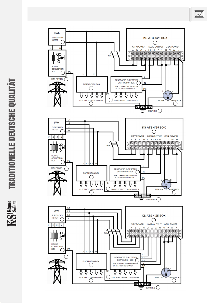
The wiring diagrams have been developed in accordance with the guidelines for planning, installation and
operation of emergency power systems developed by European power grid operators.
We recommend using three wiring options.
The generator must be connected via a 32A 230V CEE socket.
The generator must be grounded using either the screw connection or the PE pin in the generator CEE socket.
The PE pin (earth) in the generator sockets is connected to the generator housing. The N pin (neutral) in the
generator sockets is NOT connected to the generator housing and must be connected to the main earthing
busbar as a separate cable at the point of connection of the neutral from the generator on the AVR for the TN
power supply system. When switching power supply to the generator side as instructed, the ATS disconnects
not only the phase conductors, but also the neutral conductor of the external power grid.
DISCLAIMER:
These instructions are provided for reference only and must be adapted to the specific
circumstances and conditions on site during installation. The installation work must
be carried out by trained professionals with appropriate clearance and in compliance
with all applicable rules and regulations. We assume no liability for any consequences
resulting from inappropriate installation.