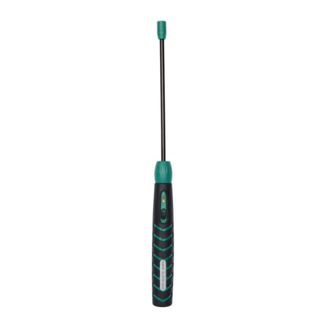
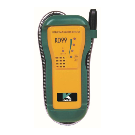
Kane CD100A User manual

2
PRODUCT FEATURES
1
. Flexible Gooseneck
2
. Visual Leak
indicator
3
. Low Battery
Indicator
4
. Power On Light
5
. Solid State semi-
conductor sensor
6
. Sensor Cover
7. Audible Leak Indicator
8. Tic Adjustment
(located on the side of
the unit)
9. Protective Boot
10. Gooseneck Clip
11. Socket for Optional
Earphone
12. Tip Light
Downloaded from Elcodis.com electronic components distributor

3
GENERAL DESCRIPTION
T
his instrument is an advanced combustible gas leak
d
etector, capable of locating many combustible, non
c
ombustible and toxic gases.
A
partial list of these gases include:
A
cetone Jet Fuel
A
lcohol Lacquer Thinners
A
mmonia Methane
B
enzene Naphtha
B
utane Natural Gas
E
thylene Propane
G
asoline - Petrol Toluene
H
ydrogen
I
ndustrial Solvents
T
he detector is factory calibrated for methane in air.
Downloaded from Elcodis.com electronic components distributor

4
Operation
1
. Turn the instrument on by rotating the thumbwheel
downwards in a non-contaminated environment. i.e.
Fresh Air.
2
. The green Power LED will be illuminated when the
unit is turned on. If the battery level is low then the
red LED will be steady and the tic rate will not be
adjustable. The battery will need replacing.
3
. Adjust to a slow uniform tic rate with the use of the
thumbwheel (approximately 2 ticks per second). This
sets the instrument to the background level, you
should start your testing by setting in fresh air. The
red LED indicator will flash in correspondence with
the tic rate. Please allow around 10 seconds for the
sensor to stabilise indicated by a steady tic rate.
However it may occasionally require up to 2 minutes
to stabilise under some conditions.
4
. The unit responds to gas with a variable audible
ticking sound. The audible tic increases in volume
when exposed to gases with 50 parts per million or
more. When gas is detected the tick rate will increase,
rotate the thumbwheel back to the steady tick,
resetting the instrument to this new background level.
Move the instrument into higher concentrations of
gas (indicated by increased tick rate) until the leak is
found.
Downloaded from Elcodis.com electronic components distributor

5
5
. The ‘Tip-light’ is used to see around the area of the
leak when in a dark environment.
6
. When this instrument is used in noisy environments,
look at the red LED which flashes more rapidly as the
tic rate increases. The optional earphone can be
plugged into the unit’s side if there is high
background noise or the operator does not want to
disturb other people. This also disables the speaker.
7
. If the tic rate becomes uncontrollable, it may be
necessary to change the sensor.
8
. The detector will respond to some leak finding
solution (e.g. Soap), so please use your detector first.
If over exposed to some gases, the detector may take
an extended period of time to return to normal.
Battery Replacement
1
. Remove the battery case cover.
2
. Replace the 9V alkaline battery. An alkaline battery
should always be used. Ensure the polarity of the
battery matches that shown in the compartment.
3
. Replace battery case cover.
Downloaded from Elcodis.com electronic components distributor

6
ELECTROMAGNETIC
COMPATIBILITY
T
he European Council Directive 89/336/EEC requires that
e
lectronic equipment does not generate electromagnetic
d
isturbances that exceed defined levels and has an adequate
l
evel of immunity to enable it to be operated as intended.
T
he specific standards applicable to this product are detailed
i
n the appendices.
S
ince there are many electrical products in use that pre-date
t
his Directive and may emit electromagnetic radiation in
e
xcess of the standards defined in the Directive there may be
o
ccasions where it would be appropriate to check the
a
nalyser prior to use. The following procedure should be
a
dopted:
•
Go through the normal start up sequence in the location
where the equipment is to be used.
•
Switch on all localised electrical equipment that might be
capable of causing interference.
•
Check that all performance are as expected. (A level of
disturbance in the performance is acceptable). If not
adjust the position of the instrument to minimise
interference or switch off, if possible, the offending
equipment for the duration of the test.
Downloaded from Elcodis.com electronic components distributor

7
A
t the time of writing this manual (April 1998) there is no
a
wareness of any field based situation where such
i
nterference has ever occurred and this advice is only given
t
o satisfy the requirements of the Directive.
Sensor Filter and Sensor Replacement
T
he sensor is housed at the tip of the gooseneck assembly.
T
o remove the sensor:
1
.Turn the unit off.
2
.Pull off the top half of the sensor housing. Pushing to
one side aids removal.
3
.With care move the ‘Tip-light’ LED to one side to
gain access to the sensor (small silver can).
4
.Unplug the sensor and replace it with a new one.
N
ote: The sensor can be fitted in either one of two ways
w
ithout affecting instrument operation.
5
. Realign the LED ensuring it sits above the sensor.
6
. Replace sensor cover by pushing it firmly in place.
Note ! the locating pin between the body and sensor
cap.
T
he sensor has a life greater than 3 years.
Downloaded from Elcodis.com electronic components distributor

8
Specifications
P
ower Suppl
y
1 x 9V battery (alkaline preferred)
S
enso
r
Solid state semi conductor
S
ensitivit
y
<50ppm methane
I
ndicators Audible: Adjustable tic rate
Visual: Flashing LED
W
arm-up 10 seconds
R
esponse Time Instantaneous
D
uty Cycle Continuous
B
attery Life 5 hours typical use
D
imensions
8 “ H x 4 “ W x 1.5” D
205mm x 100mm x 36mm
W
eight
15 oz / 460 gm
P
robe Length 18 inches / 460 mm
O
perative 0-50oC / +32-122oF
Protection Against Electric Shock
(in accordance with EN 61010-1 : 1993)
T
his instrument is designated as Class III, SELV.
Downloaded from Elcodis.com electronic components distributor
9
APPENDIX
ELECTROMAGNETIC
COMPATIBILITY
This product has been tested for
compliance with the following
generic standards:
EN 61000-6-3
EN 61000-6-1
and is certified to be compliant
Specification EC/EMC/KI/CD100A
details the specific test configuration,
performance and conditions of use.
P
lease Note: Batteries used in this instrument should be
disposed of in accordance with current
legislation and local guidelines
.
Downloaded from Elcodis.com electronic components distributor
Table of contents
Other Kane Gas Detector manuals
Popular Gas Detector manuals by other brands

Honeywell
Honeywell BW GasAlertMicro 5 user manual

Gas Detection
Gas Detection GD 2400 operating manual

Crowson
Crowson T4 User & Operator Manual

brennenstuhl
brennenstuhl BCN 1221 Directions for use

Riken Keiki
Riken Keiki SD-1DGH-AS operating manual

BW Technologies
BW Technologies GasAlertMicro 5 user manual