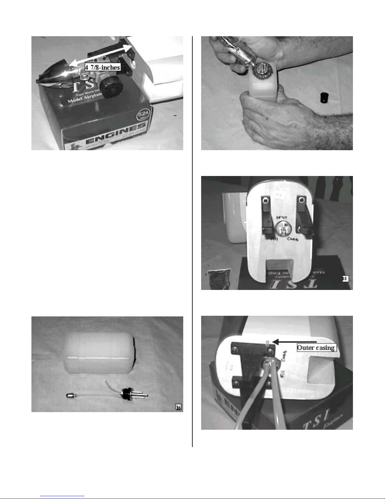
KANGKE INDUSTRIAL FUN-50 User manual

FUN-50
ARF
ASSEMBLY MANUAL
This Manuel is the sole property of Kangke Industrial USA, Inc. Reproducing any part without the
consent of Kangke Industrial USA, Inc. is a lawful violation.
Kangke Industrial USA, Inc. 65 East Jefryn Blvd. Deer Park NY 11729
http://www.kangkeusa.com E-mail: [email protected]
1-877-203-2377 fax 1-631-274-3296
Warranty: Kangke Industrial USA Inc. guarantees the kit to be free of defects in both material and workmanship at the date of
purchase. This warranty does not cover any parts damaged by use or modifications. In no case shall Kangke Industrial’s liability exceed the
purchase cost of this kit. Since Kangke Industrial has no control of final assembly and material used by user for final assembly, no liability
shall be assumed or accepted for any damage resulting from the use by user of final user-assembled products. This kit has been flight test for
normal use. If the plane will be used for extremely high stress flying, the modeler is responsible for reinforcing the high stress points. Inspect
this kit immediately after receiving it, report any missing and damaged parts within 10 business days otherwise the claim may be denied.

Congratulations!
Kangke Industrial USA, Inc. brings you one of the finest ARF fun-fly models available. Skilled
craftsmen combined with top grade materials and precision jigs have all come together to produce an
aircraft with outstanding flight qualities. If you follow the directions carefully the performance of this
aircraft will surely please you.
Specifications:
Length 56 in.
Wing Span 61 in.
Area 735sq. in.
Weight 5-6 lbs.
Engine (2 Cycle) 40-52
(4 Cycle) 60-70
Kit Contents:
Fuselage 1
Wing panel 2
Ailerons 2
Cowling 1
Canopy 1
PACK 1
Stabilizer 1
Elevator 2
Fin 1
Rudder 1
Dihedral brace 1
PACK 3
Fuel tank 1
Wheels 2
Tail gear 1
Tail wheel 1
Control horn 4
Control wire 4
Motor mount 1
Hardware pack 1
Pack 4
Manual 1
Decal kit 1
The following additional items will also be needed to build the CAP-SPORT
HOBBY ITEMS:
4 oz. 30 min. epoxy
Popsicle sticks
Hobby knife
Thin CA .5 oz.
Radio 4-channel min.
4 servos
RTV silicone
Motor
Muffler
Spinner
Fuel line
Screwdrivers
HOUSEHOLD ITEMS:
Alcohol
Masking tape
Ruler
Felt tip pen
Pliers
5/32 drill
1/8 drill
Clothes pins
Canopy glue
Paper towels
Read each step of the instructions carefully. Be sure you understand what is required and what the
procedure is before you glue or cut anything. How well you assemble this model will have a direct effect
on its flight characteristics.
2

WING ASSEMBLY
Remove the tape from the servo wire pull string
at the center of the wing. Work the string through
the exit hole in the wing bottom and secure.
Measure the dihedral brace, locate and mark its
center. Insert a pin in the edge of the brace at the
mark. Because there is no dihedral there is no top
or bottom to the brace.
Trial fit the dihedral brace in its box in both wing
panels. The brace should have a snug fit, sand
lightly if necessary.
The following steps must be done quickly before
the epoxy has time to set up. Read the procedure
and gather the materials before starting.
Mix a small amount of 30-minute epoxy. Spread
the epoxy in the dihedral box top, bottom, and
sides about 1 inch in on both wing panels. The
snug fit of the brace will push it down the box.
Apply epoxy to one half of the wing spar and
slide it into position. Spread the epoxy that oozes
out over the wing mating surface as well as the
other half of the wing spar. Slide the other wing
panel in place, remove the pin and wipe off the
excess epoxy with a paper towel moistened with
alcohol.
3

Stretch masking tape across the joint in such a
way as to apply pressure to the joint. Lay the
wing flat. DO NOT DISTURB THE WING
UNTILL THE EPOXY HAS FULLEY CURED.
FUSELAGE ASSEMBLY
Locate and insert a pin in the firewall on the top
of the fuselage.
Remove the elevators from the stabilizer. Locate
and draw a line down the center of the stabilizer.
Looking through the rudder slot for the line,
center the stabilizer in the fuselage. Using a piece
of string go back and forth between the ends of
the stabilizer adjusting it till it is centered and
square to the fuselage. DO NOT GLUE
Use a felt tip pen to mark the outline of the
fuselage on both the top and bottom of the
stabilizer. Remove the stabilizer. Cut through the
covering about 1/8-inch inside the lines and
carefully remove the covering exposing the wood.
{Be careful not to cut into the wood, as this
would weaken the structure}
4

Place the elevator link in the fuselage, hold it to
the rear with a rubber band. Open the link slot in
the rear center of the stabilizer.
Slide the stabilizer back into the fuselage, leaving
3/8-inch of bare wood exposed. Coat the wood
top and bottom with epoxy, slide the stabilizer
through the fuselage exposing the wood on the
other side, and coat the wood with epoxy. Center
the stabilizer and use the string as before to verify
its alignment. Wipe the excess epoxy with a paper
towel moistened with alcohol. Allow to cure
before proceeding.
Remove the rudder from the fin. Slide the fin into
the fuselage and with a felt tip pen outline the
fuselage. Remove the covering 1/8-inch down as
was done with the stabilizer.
Coat both sides of the wood on the fin with epoxy
{do not coat the inside of the slot or epoxy will be
pushed down on to the elevator link}. Push the fin
in the slot until it bottoms against the fuselage.
Wipe off excess epoxy with a paper towel
moistened with alcohol.
Install the engine mount beams. Locate the
engine on the beams with the back of the spinner
4-7/8-inches from the firewall. Remove the
engine
5

FUEL TANK
Pass the two metal tubes through the silicone
stopper. Place the large endplate on the outside
and the small endplate on the inside. Press the
screw through the outer plate and through the
silicone stopper, screw it into the inner plate do
not tighten. Slide the metal tubes so 1/2-inch
extends past the outer side of the silicone stopper.
Gently bend the long tube up to point into the
“bubble” at the top of the tank. Push the flop
weight into one end of the silicone tube. Cut the
tube so that when the other end is pushed on the
short metal tube the flop weight will be
approximately 3/8-inch from the back of the tank.
Slide the assembly into the tank, making sure to
get the vent tube in or near the top. Tighten the
screw until the stopper is tight in the opening. It is
best to label the vent and carb lines with a felt tip
marker on the outer plate to avoid confusion later.
Apply a 1/4-inch bead of RTV silicone around
the tank stopper.
Slide the fuel tank into position, wedge a piece of
foam in at the rear of the tank to hold it in
position. Allow the RTV to cure.
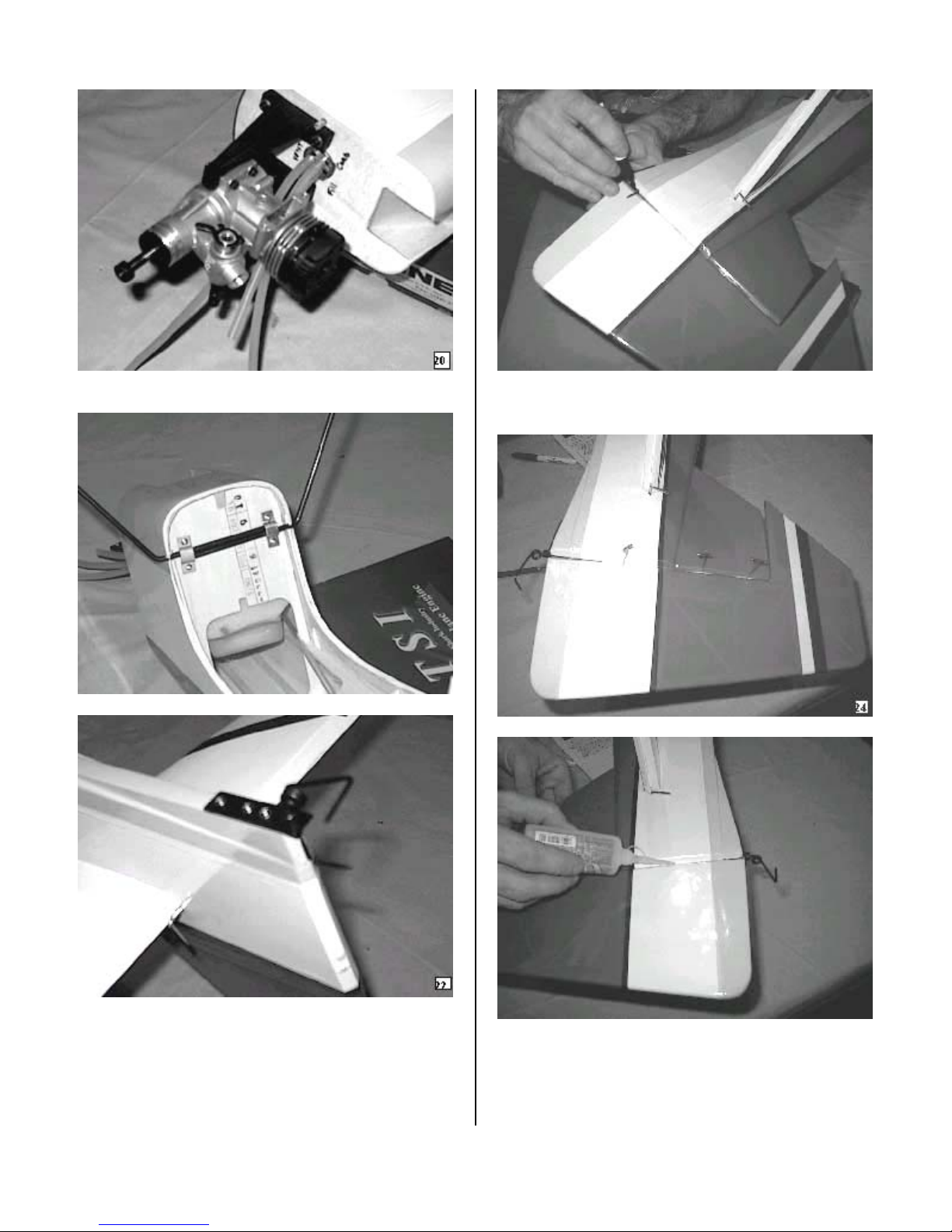
Drill a hole in the firewall and install the throttle
wire outer casing.
Install the fuel lines.
Install the engine with the supplied screws and
lock nuts.
6

Install the wire main landing gear with the
supplied straps and screws.
Install the tail wheel bracket as shown with the
provided screws.
With the rudder correctly aligned, mark and drill
the hole for the tail wheel tiller arm.
Insert pins on the centerline of each hinge to
prevent them from sliding too far in. Install the
hinges, rudder and tiller arm.
With the rudder correctly aligned, remove the
pins and place a drop of thin CA on each side of
each hinge.
Remove the covering over the elevator link holes
at the inside corner of each elevator half.
7

Use a toothpick to coat the inside of the hole with
epoxy.
With pins on the center of the hinges slide the
elevator half in position. Be sure to engage the
elevator link. {DO NOT CA THE HINGE}
Repeat the procedure for the other side.
With the two elevator halves in position and
properly aligned side to side, remove the pins and
CA the hinges.
Use the same procedure to install the ailerons on
the wing. Insert pins in the center of the hinge,
install and align the aileron, then apply one drop
of thin CA to each side of the hinge.
Because of the lightweight airframe, the FUN-50
was designed to use standard 40-ounce servos.
Our prototype used HITEC HS-425BB with
excellent results. Use these directions as a guide
and install the servos following your radio
manufactures instructions.
8

Open the elevator and rudder servo holes in the
rear of the fuselage. Test fit your servos and
install the appropriate length extension.
Install the servos following the manufacture
instructions. For the rudder side, fabricate a push
rod by making a “Z” bend 9 ¾-inches from the
threaded end. Install the control horn in such a
way that the clevis holes line up with the hinge
line and the tail wheel tiller arm is pinched.
The elevator push rod is made in the same
fashion. The length for the elevator is 5 ¾-inches.
Mount the control horn 3/16-inch in from the
inside edge of the elevator.
Test fit the aileron servos in the wing. Add the
servo wire extension and use the string to pull
through the wing. Fabricate the push rod by
making a “Z” bend 5-inches from the threaded
end. Mount the aileron bellcrank in the aileron
hard point so the push rod is as straight back as
possible.
Install the throttle servo in the servo tray as
shown. With the servo in the closed position close
the carburetor and fabricate the push rod using a
“Z” bend at each end.
9

Trim the canopy along the indicated lines.
Carefully position the canopy of the fuselage and
tape in place. Secure the canopy with the
provided screws.
Open the required holes for your engine {cooling,
carb, needle valve, and exhaust}. Align the cowl
with the spinner leaving a ¼-inch gap. Secure the
cowl with the provided screws.
Install the wheels on the axles using the collars
and set screws.
Install the tail wheel and collar.
Install the remainder of the radio gear following
the manufacture instructions. Open the holes in
the wing for the hold down screws. Install the
wind and belly pan with the provided screws.
BALANCE
The center of gravity must be located from 3 1/2
to 4 1/2-inches behind the leading edge of the
wing. Moving it to the forward side of the range
will increase the stability of the aircraft, moving it
aft will increase control response. We recommend
the forward position for initial flight tests.
The final step is the decals and covering. The
covering may have developed wrinkles and they
can be easily removed with a modelers heat gun.
10

Be careful when heating the covering not to twist
the control surfaces. Should a surface develop a
twist it can be easily removed by GENTLY
twisting while applying heat. Apply the decals
after the covering has been corrected.
CONTROL THROWS
Double check all controls move in the proper
direction
With your radio on, center all trims and adjust the
clevises so all control surfaces are straight.
Measure the control surface movement at the
widest part of each surface. Use the servo horns
and bell crank holes to adjust the control throw.
For your first flights the control throws should be
set to the following:
Elevator 3/4-inch up / down
Rudder 1 ½- inch right / left
Aileron 3/8-inch up / down
MOTOR SET UP
Be sure the motor is properly broken in using the
manufacture instructions. Set the throttle throw to
shut the motor off when the trim is pulled down
and idles reliably with the trim up.
After the motor is set, run one tank of gas at full
throttle, measure how much time it takes to run
the tank dry.
CONGRADULATIONS you are now ready for
test flights.
Before leaving for the field be sure your batteries
are fully charged and you have all the required
support equipment {fuel, starter, glow driver,
ect.}.
Although the FUN-50 will fly well in wind, wait
for a nice day.
At the field have a helper hold the airplane,
following the radio manufactures instructions
perform a range check of the radio. Do this with
the motor off, start the motor and do it again.
Perform this test EVERY TIME YOU GO TO
FLY!
TRIMING BASIC FLIGHT
The FUN-50 is NOT a trainer. A true aerobatic
aircraft, it goes only where you point it and will
not recover to level flight without control input. If
you do not have high performance experience
seek the help of someone who does.
Line up on the center of the runway and slowly
open the throttle, using the rudder to maintain
directional control. Once the tail is up apply a
little up elevator and allow the plane to gently lift
off the runway. Keep the climb angle and turns
shallow until you reach a safe altitude. Reduce
the throttle to about 60% power. With the
airplane flying away from you adjust the radio
aileron trim tab till the wing stays level. Turn and
line up the plane with the runway. Adjust the
elevator trim till the plane maintains level flight.
Once again with the airplane flying away from
you adjust the rudder trim till the fuselage tracks
straight {it may be necessary to correct the
aileron trim after this procedure}. Continue to fly
and trim until the aircraft is tracking well, land
before the fuel runs out. Carry a little power on
final approach until over the end of the runway,
then cut power to idle, hold the plane just off the
runway till the airspeed bleeds off and the plane
settles on. If the landing is too long add power go
around and try again, don’t try to force it to the
ground.
Now its time to zero out the trims. To do this
measure the control location, center the trim tab
on the radio and adjust the servo horn for large
changes, the control clevis for small changes. For
example if after the flight the rudder is 3/16 inch
to the right, center the radio trim and adjust the
clevis till the rudder once again measures 3/16
right. By doing this whenever you fly, setting the
radio trims at center will result in a well-trimmed
11

plane. Increase the control travel, as you become
more familiar with the flight characteristics until
loops take about 50 feet and knife edge can be
maintained with 80% stick deflection. Final roll
rate should be 300-360 degrees per second.
If you have followed the procedures in this
Manuel you will now be rewarded with one of the
finest flying sport models available. All primary
aerobatic maneuvers are at your fingertips and
the aircraft will perform them with ease.
12
Table of contents
Other KANGKE INDUSTRIAL Toy manuals
Popular Toy manuals by other brands

Hasbro Gaming
Hasbro Gaming Elefun FLYERS manual

Enabling Devices
Enabling Devices Farmer Mac user guide

Faller
Faller PLASTER SILO AND BUILDING-SITE TRAILER Assembly instructions

REVELL
REVELL B-17F "Memphis Belle" manual

Black Horse Model
Black Horse Model AT.6-Texan Instruction manual book

Enabling Devices
Enabling Devices Tic Tac Toe user guide