KANGKE INDUSTRIAL TIGER SHARK-40 User manual

TIGER SHARK-40
ARF
ASSEMBLY MANUAL
Kangke Industrial USA, Inc. 65 East Jefryn Blvd. Deer Park NY 11729
http://www.kangkeusa.com E-mail: [email protected]
Tel: 1-877-203-2377 Fax: 1-631-274-3296

Congratulations!
Kangke Industrial USA, Inc. brings you one of the finest Tiger Shark models available. Skilled
craftsmen combined with top grade materials and precision jigs have all come together to produce an
aircraft with outstanding flight qualities. If you follow the directions carefully the performance of this
aircraft will surely please you.
Specifications:
Length 54.5 in.
Wing Span 47.5 in.
Area 535 sq. in.
Weight 5.5-6.5 lbs.
Engine 40-52 2 Cycle
Kit Contents:
Fuselage 1
Wing panel 1
Ailerons 2
Canopy 1
PACK 1
Stabilizer 1
Elevator 1
Fin 1
Rudder 1
PACK 2
Servo tray 1
Servo block 2
Servo rails 2
PACK 3
Fuel tank 1
Wheels 3
Main gear 2
Nose Gear 1
Control horn 1
Control wire 6
Control rod 1
Bellcrank 1
Hardware pack 1
Clevises 5
Pack 4
Manual 1
Decal kit 1
The following additional
items will also be needed to
build the Tiger Shark
HOBBY ITEMS:
4 oz. 30 min. epoxy
Popsicle sticks
Hobby knife
Med. CA 1 oz.
Radio 4-channel min.
4 servos
Fuel line 20-inches
Motor (Tiger Shark .40/52)
Muffler
Spinner (Super Kraft 2.25”)
18-inch servo extension
Canopy glue
HOUSEHOLD ITEMS:
Paper towels
Alcohol
Masking tape
Ruler
Felt tip pen
Screwdrivers
Pliers
RTV silicone
Sewing thread
5/32 drill
1/4 drill
1/8 drill
1/16 drill
Clothes pins
Read each step of the instructions carefully. Be sure you understand what is required and what the procedure
is before you glue or cut anything. How well you assemble this model will have a direct effect on its flight
characteristics.
This manual is the sole property of Kangke Industrial USA, Inc. Reproducing any part without the consent of
Kangke Industrial USA, Inc. is a lawful violation.
Warranty: Kangke Industrial USA Inc. guarantees the kit to be free of defects in both material and workmanship at the date of purchase. This
warranty does not cover any parts damaged by use or modifications. In no case shall Kangke Industrial’s liability exceed the purchase cost of this
kit. Since Kangke Industrial has no control of final assembly and material used by user for final assembly, no liability shall be assumed or
accepted for any damage resulting from the use by user of final user-assembled products. This kit has been flight test for normal use. If the plane
will be used for extremely high stress flying, the modeler is responsible for reinforcing the high stress points. Inspect this kit immediately after
receiving it, report any missing and damaged parts within 10 business days otherwise the claim may be denied.
2

Note that because of the unique design of the Tiger
Shark, the assembly sequence is unusual when
compared to most other ARF designs. We at
KANGKE have found this to be the best sequence
and recommend you do not deviate from it.
FUSELAGE
Carefully trim the covering and remove the access
hatch as shown in the photo. Secure the loose edge
of the covering with a covering iron.
Locate the fin support block. Slide the block into
the rear of the fuselage. DO NOT GLUE!
Using a ¼-inch drill, make a hole through the
fuselage as far to the rear of the fin slot as possible.
Drill another ¼-inch hole 1-inch forward of the rear
of the fin slot. Remove the fin support block.
Using a razor knife, remove the balsa between the
holes making a slot. Reinstall the fin support block.
DO NOT GLUE!
Using a small saw blade, notch the rear of the fin
support block, as well as the fuselage 1/8-inch at the
center of the slot { this is for rudder bellcrank
clearance}. Remove the fin support block.
Using a razor knife, make a slot in the rear of the
fuselage opening for the rudder bellcrank support-
bearing tab.
Test fit the bellcrank in the rear of the slot DO NOT
GLUE!
3

Insert the rudder support block in the fuselage,
using a felt tip pen mark the outline of the fuselage
on the fin support block. Remove the support block.
Using a razor knife, slice and remove the covering
1/8-inch below the drawn line.
Mix a small amount of 30-min epoxy, coat the bare
wood on the fuselage and slide in the rudder support
block. Allow to cure.
Coat the bellcrank wire generously with petroleum
jelly to be sure glue does not stick to it, be careful
not to get any on the support tab. Using a tooth pick
work a small amount of 30-minute epoxy into the
support tab slot and install the bellcrank.
Be sure the bellcrank is in its slot and allow to cure.
If the bellcrank enters the fin slot, the fin will
prevent it from moving once it is installed.
4

Open the screw holes in the stabilizer and trial fit to
the fuselage. Mark the location of the elevator on
the stabilizer. Using a toothpick work a small
amount of epoxy into the hinge slots, wipe off the
excess with a paper towel moistened with alchol
and install the hinges and elevator.
Using the servo as a spacer, mark the location of the
elevator servo mounting blocks. Depending on the
servo used, some modifacation of the stabilizer
mount tab may be nessasary.
Remove the covering at the mount location and
epoxy the mount in place. Be sure the hard wood on
the mount will be against the servo mounting tabs.
Install the servo. Line up and install the elevator
bellcrank. Screw a clevis on to a threaded rod,
center the servo and mark the servo arm hole on the
rod. Make a “Z” bend in the rod and install.
Install the rudder control tab on the rudder
bellcrank.
Using the servos as spacers install the servo
mounting rails as shown with epoxy. Install the
rudder and throttle servos.
5

Locate and drill a 5/32-inch hole in the fire wall for
the throttle control wire and casing.
Drill a 5/32-inch hole next to the nose gear support
block. Rough the casing at both locations and epoxy
in place.
The fuel tank is mounted sideways. Trial fit the tank
in its opening {the offset of the tank goes to the
motor side} Mark the top to avoid confusion and
install the vent and pickup lines as shown. Do not
tighten the screw.
Apply a ¼-inch bead of RTV silicone around the
front of the tank. Press the tank into position and
while holding it there tighten the screw.[the rubber
plug will expand holding the tank in position while
the RTV cures]
Install the fuel and vent lines. Make a “Z”bend in
the end of the throttle wire and install the wire with
the motor.It is sometimes easier to install the motor
without the carburator then install the carb and
throttle wire.
Insert the nosegear through the fuselage, then the
retaining collar, nose gear block and finally the
6

steering bellcrank. Make a “Z” bend in the steering
control rod and install in the steering bellcrank.
With the servo centered and the nose wheel straight,
mark the control rod and install with another”Z”
bend as shown.
Trial fit the fin and rudder. When satisfied with the
fit, remove the rudder and using a felt tip pen, mark
the fuselage line on both sides of the fin.
Using a razor knife, cut and remove the covering ¼-
inch below the line.
Coat the rudder bellcrank with petroleum jelly.
Epoxy the fin in place using the lines as a guide.
Test fit for rudder clearance before the epoxy cures.
Clean the excess with a paper towel moistened with
alchol. When cured, install the rudder as was done
with the elevator.
Begin the rudder control rod by bending one rod 6
1/2-inches from the threaded end. Bend another rod
2 ¼-inches from the threaded end. Cut the rods ¼-
inch after the bend. Be sure not to cut the side with
the threads.
Insert the cut end into the hole in the wood dowel,
press the rod into the slot in the dowel. Wrap the
end tightly with thread and cover with CA. screw a
clevis on the rod. Repeat the process on the other
end.
Install the short end on the rudder bellcrank the long
end on the servo. Adjust the rod length till the
rudder is straight.
7

Run the servo extension through the fuselage, plug
in the elevator servo and install the stabilizer.
Cut a notch in the lock down tab of the access hatch
to clear the nose gear collar.
Install the access cover and secure with a screw.
Install the front wheel.
Begin the wing by installing the hinges and ailerons
using the same procedure as before. Make a mark
on the top of the wing 6-inches from the trailing
edge.
Line up the forward edge of the servo doubler with
the mark. Center the doubler on the wing and using
a felt tip pen trace its outline.
Using a razor knife, trim and remove the covering
1/8-inch inside the lines.
8

Epoxy the servo doubler in place. Cut the center out
as nessesary to fit the servo. Mount the servo
following the manufactures instructions. Fabricate
the control rods as before and install.
Cut the covering over the slots in the bottom of the
wing for the landing gear. Insert the landing gear
wire in the slot, and secure with straps and screws
as shown. Instal wheel collars and wheels as before.
Trim the canopy along the scribe lines. Sand the
edges smooth with fine sandpaper if nessasary. Trial
fit the canopy and when satisfied install with
canopy adheasive. The canopy may be tinted using
canopy dye from your local hobbie supplier. Be
sure not to let the dye temp exceed 140-degrees.
The exhaust cone must be painted and glued in
place using canopy adheasive.
WEIGHT AND BALANCE
Nothing affects the way a plane flies more than
weight and balance. Failure to perform this
procedure may result in an aircraft that is at best
difficult to control and at worst impossible to fly.
9

Even small changes in the balance point make large
changes in stability. For your first flights we
recommend using a balance point at the forward
end of the center of gravity {C.G.} range, this
location will provide the most stability. As your
comfort and skill increase slowly move the C.G. aft
to increase the control response.
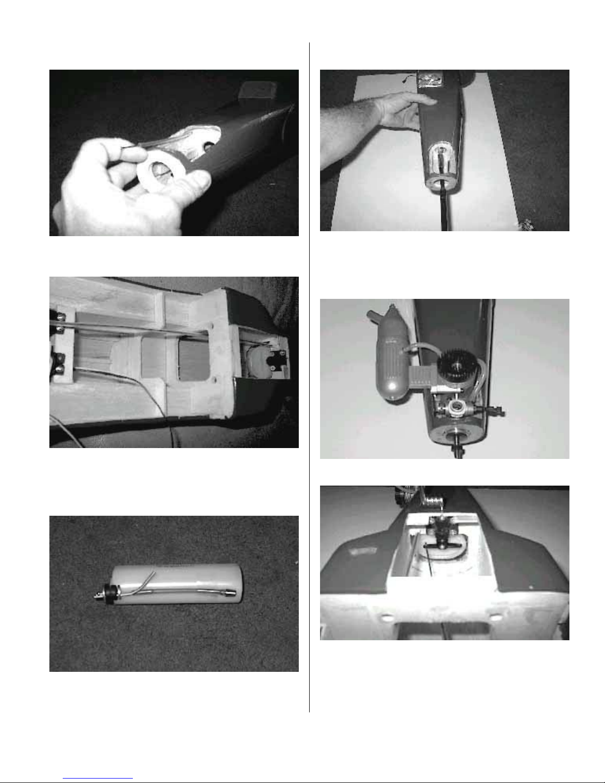
Lay a strip of masking tape along the top of each
wing as shown. Make two marks on the tape one 5
1/2-inches, one 6 1/4-inches back from the leading
edge of the wing. Repeat on the other side of the
fuselage. These marks represent the limits of the
C.G. range.
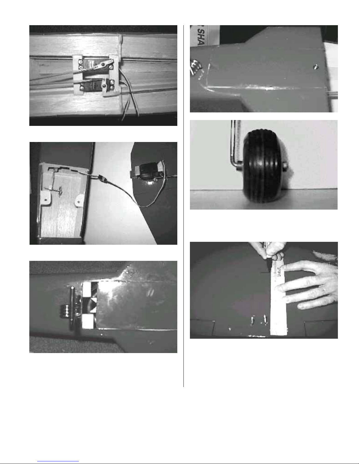
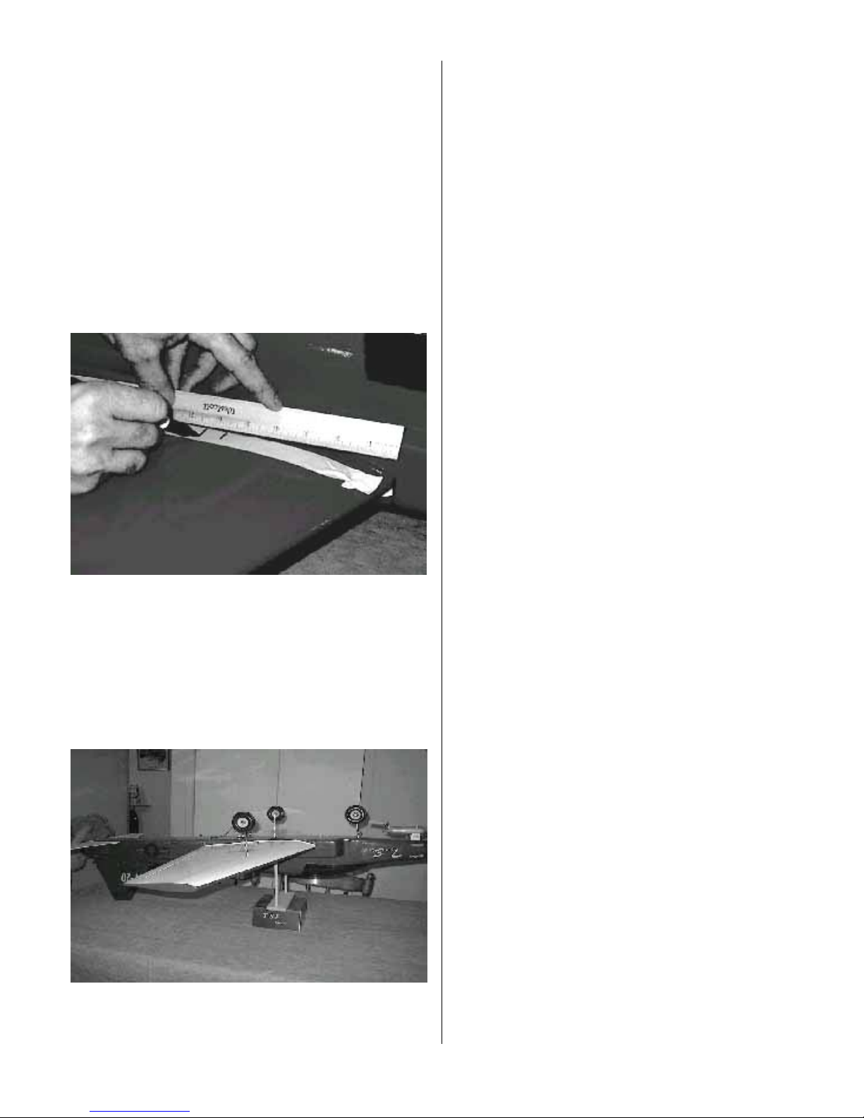
Turn the aircraft upside down and support it from
between the two marks. Slide the battery pack to a
position where the plane will balance level to
slightly nose heavy. Mount the battery inside the
fuselage at the determined location. Install the on
off switch in a convenient location per the
manufactures instructions. Reinstall the wing and
check the C.G. again. If necessary add weight to the
nose or tail.
CONTROL THROWS
Double check all controls move in the proper
direction
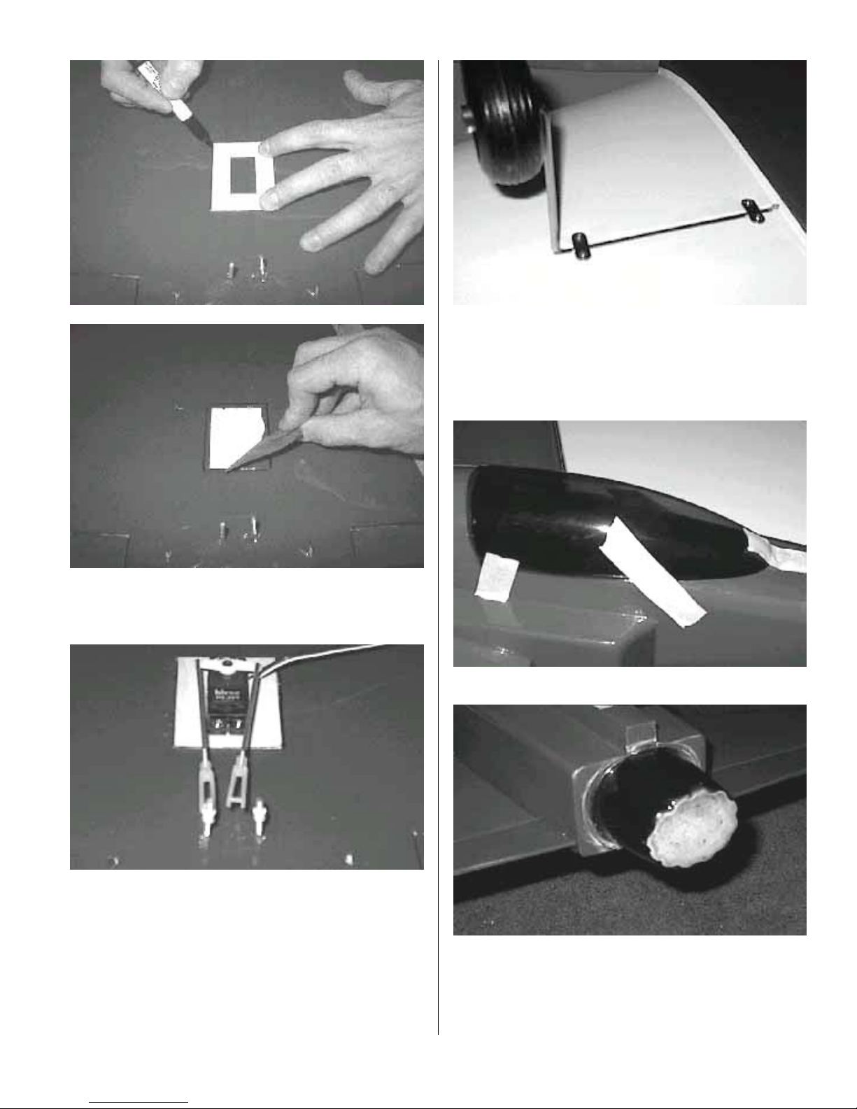
With your radio on, center all trims and adjust the
clevises so all control surfaces are straight. Measure
the control surface movement at the widest part of
each surface. Use the servo horns and bell crank
holes to adjust the control throw. For your first
flights the control throws should be set to the
following:
Elevator 1/2-inch up / down
Rudder 1 ½- inch right / left
Aileron 1/4-inch up / down
MOTOR SET UP
Be sure the motor is properly broken in using the
manufacture instructions. Set the throttle throw to
shut the motor off when the trim is pulled down and
idles reliably with the trim up.
After the motor is set, run one tank of gas at full
throttle, measure how much time it takes to run the
tank dry.
CONGRADULATIONS you are now ready for test
flights.
Before leaving for the field be sure your batteries
are fully charged and you have all the required
support equipment {fuel, starter, glow driver, etc.}.
Although the TIGER SHARK will fly well in wind,
wait for a nice day.
At the field have a helper hold the airplane,
following the radio manufactures instructions
perform a range check of the radio. Do this with the
motor off, start the motor and do it again. Perform
this test EVERY TIME YOU GO TO FLY!
TRIMING BASIC FLIGHT
The TIGER SHARK is NOT a trainer. A true
aerobatic aircraft, it goes only where you point it
and will not recover to level flight without control
input. If you do not have high performance
experience seek the help of someone who does.
Line up on the center of the runway and slowly
open the throttle, using the rudder to maintain
directional control. Once the tail is up apply a little
up elevator and allow the plane to gently lift off the
runway. Keep the climb angle and turns shallow
10

until you reach a safe altitude. Reduce the throttle to
about 60% power. With the airplane flying away
from you adjust the radio aileron trim tab till the
wing stays level. Turn and line up the plane with the
runway. Adjust the elevator trim till the plane
maintains level flight. Once again with the airplane
flying away from you adjust the rudder trim till the
fuselage tracks straight {it may be necessary to
correct the aileron trim after this procedure}.
Continue to fly and trim until the aircraft is tracking
well, land before the fuel runs out. Carry a little
power on final approach until over the end of the
runway, then cut power to idle, hold the plane just
off the runway till the airspeed bleeds off and the
plane settles on. If the landing is too long add power
go around and try again, don’t try to force it to the
ground.
Now its time to zero out the trims. To do this
measure the control location, center the trim tab on
the radio and adjust the servo horn for large
changes, the control clevis for small changes. For
example if after the flight the rudder is 3/16 inch to
the right, center the radio trim and adjust the clevis
till the rudder once again measures 3/16 right. By
doing this whenever you fly, setting the radio trims
at center will result in a well-trimmed plane.
Increase the control travel, as you become more
familiar with the flight characteristics until loops
take about 100 feet and final roll rate should be 200-
250 degrees per second.
If you have followed the procedures in this Manuel
you will now be rewarded with one of the finest
flying sport models available. All primary aerobatic
maneuvers are at your fingertips and the aircraft
will perform them with ease.
11
Table of contents
Other KANGKE INDUSTRIAL Toy manuals
Popular Toy manuals by other brands

Lionel
Lionel Pioneer Zephyr owner's manual

Tiger
Tiger 99X Games CRASH BANDICOOT 99-004 instructions

Carl Goldberg Products
Carl Goldberg Products Pitts Monster 12 manual

Badger Basket
Badger Basket MINICHEF 9982 Assembly instructions

Hobby-Lobby
Hobby-Lobby albatros DVA Assembly manual

WowWee
WowWee Alive Mini White Tiger cub quick start guide