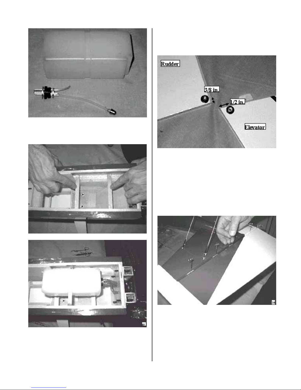
KANGKE INDUSTRIAL LASER 2000 User manual

LASER 2000
ARF
ASSEMBLY MANUAL
KANGKE INDUSTRIAL USA Inc.
65 East Jefryn Blvd. Deer Park, New York 11729
http://www.kangkeusa.com E-mail: [email protected]
1 877-203-2377 Fax 1-631-274-3296
This manual is the sole property of KANGKE INDUSTRIAL USA inc. Reproducing any part
without the consent of Kangke Industrial USA Inc. is a lawful violation.
Warranty: Kangke Industrial USA Inc. guarantees the kit to be free of defects in both material and workmanship at the date of
purchase. This warranty does not cover any parts damaged by use or modifications. In no case shall Kangke Industrial’s liability exceed the
purchase cost of this kit. Since Kangke Industrial has no control of final assembly and material used by user for final assembly, no liability
shall be assumed or accepted for any damage resulting from the use by user of final user-assembled products. This kit has been flight test for
normal use. If the plane will be used for extremely high stress flying, the modeler is responsible for reinforcing the high stress points. Inspect
this kit immediately after receiving it, report any missing and damaged parts within 10 business days otherwise the claim may be denied.

Congratulations!
The LASER 2000 is one of the finest ARF high performance models available. Originally
designed as a competition aircraft, It has proven itself time and time again in the winner circle. All the
great flying characteristics have been retained, along with all the special design features of a full bread
competitor. The tail surfaces are removable for shipping. The flying wires are functional. Several servo
and engine options are available to suit you personal needs and the highest quality hardware available
has been included. When properly assembled if can perform anything in the current realm of I.M.A.C or
T.O.C high Alfa maneuvers.
WARNING! As model aircraft get larger and more powerful, the risk for injury increases.
KANGKE’s extensive testing procedures insure a high quality kit that has gone through many steps to
provide you with a safe reliable airframe. Nothing we can do however will make up for poor assembly
or irresponsible behavior at the field. A model this size and weight traveling at 80 MPH contains enough
energy that if it were to contact another person, the injuries would be extensive possibly fatal. The safe
operation of this model is yours and yours alone. If you are a beginner or have never flown a model of
this size and power, you should not make the attempt without the help of an experienced pilot.
Enjoy this aircraft, you may never find one that flies better!
Specifications:
Length 70 in.
Wing span 87 in.
Wing area wet 1204 sq.
in.
Surface area 1421 sq.
in.
Weight 16-18 lbs.
Wing load 27-29 oz.
Engine 2.4-3.2
C.I. Gas
Kit Contents:
Fuselage 1
Wing panel 1
Ailerons 2
Cowling 1
Canopy 1
Main gear 1
Stabilizer 1
Elevator half 2
Rudder 1
Fin 1
Servo mount 1
Fuel tank 1
Wheels 2
Tail wheel 1
Control horns 6
Control rods 6
Hardware pack 1
Wheel pants 2
Set flying wires 1
Wing tube 1
The following items will also
be needed to assemble your
LASER 2000:
Hobby Items:
30-min. epoxy
Hobby Knife
4-6channel radio
Gas line
5 heavy duty servos
Engine
Med. CA 1-oz.
Muffler
Household Items:
Paper towels
Alcohol
Popsicle sticks
Felt tip pen
Screwdrivers
Wax paper
Pliers
String
If you are familiar with the assembly of ARF type aircraft, you will find the assembly sequence to
seem out of order. This is because of some of the unusual features of a competition airframe.
Please follow the sequence as written. The Laser 2000 will take 20-25 hours to complete.
Read each step of the assembly carefully. Be sure you understand what is required for each
procedure before you glue of cut anything. How well you assemble this model will have a direct
effect on its flight characteristics. Do not omit any steps. Take your time and enjoy the building
process.

ASSEMBLY
Because the tail section is removable, the flying
wires are functional. Locate the pre-drilled
holes in the fin and stabilizer for the flying
wires attach brackets. The holes are small and
difficult to find. They must be opened with a
pin.
Use the rudderpost to locate the alignment
holes in the rear of the fuselage. Open the
holes.
Assemble the tail as shown with a piece of
waxed paper between the stabilizer and the
rudder support block. Install the stabilizer
hold down screws for alignment, do not tighten
Use a felt tip marker to outline the rudder
support block on the side of the fin.
With a sharp hobby blade and a straight edge,
slice the covering ¼ inch below the marked
line. Be careful not to slice into the wood, as
that would weaken the structure. Peel away
the covering a shown.
Apply a thin coat of epoxy to the inside of the
rudder support block. The waxed paper will
prevent it from sticking to the stabilizer. Slide
the rudder all the way in, engaging the
rudderpost alignment pins. Wipe away the
excess epoxy with a paper towel moistened
with alcohol. Allow to cure before moving.

Bend all the flying wire attach brackets to a
45-degree angle and install in the fin and
stabilizer as shown. Tighten the screws only to
the point where the stabilizers wood begins to
crush, do not over tighten. A small dab of RTV
silicone will prevent them from vibrating loose.
Measure the firewall across the top and
bottom, locate and draw the vertical
centerline. Measure down 1 3/8-inches from
the top of the firewall and draw a horizontal
line. Where the lines cross should be the center
of the crankshaft of the engine.
The distance from the back of the spinner to
the firewall must be at least 6 7/16-inches for
proper clearance with the cowl. The BRISON
2.4 used on the prototype required a 1 1/8-inch
spacer. The size of the spacer you need will
depend on your choice of engine.
When installing the tail surfaces for use apply
a thin bead of RTV silicone to the stabilizer
rudder support-mating surface. Install the
flying wire attach bracket ¾-inch behind the
rudder servo opening as shown.
Install the flying wires on the bottom of the
stabilizer. The short wires in the front, the
long wires in the rear. Square the stabilizer by
adjusting the wire tension. NOTE: Do not over
tighten the wires, excess tension may distort
the stabilizer.

Install the upper flying wires; try to keep the
tension on all the wires equal. The wires
should be adjusted tight enough so there is no
endplay, but not so tight as to cause distortion
of either the fin or the stabilizer.
Install the main landing gear with the supplied
screws and washers. When installed correctly
the gear will have a slight sweep forward.
Install the tail wheel bracket. Align the tail
wheel pivot hole with the back edge of the
rudderpost.
The airframe can now stand on its gear
allowing clearance for the cowl. Temporarily
install the canopy deck. Line up the cowl and
open any holes that are necessary for engine /
exhaust clearance. Locate the holes for the
cowl mount. Remove the cowl and deck.
Assemble the gas tank. Be sure the flop tube
does not contact the rear of the tank. Bend the
vent line to the top of the tank and install the
fill tube if third line refueling is to be used.
Table of contents
Other KANGKE INDUSTRIAL Toy manuals
Popular Toy manuals by other brands

FUTABA
FUTABA GY470 instruction manual

LEGO
LEGO 41116 manual

Fisher-Price
Fisher-Price ColorMe Flowerz Bouquet Maker P9692 instruction sheet

Little Tikes
Little Tikes LITTLE HANDIWORKER 0920 Assembly instructions

Eduard
Eduard EF-2000 Two-seater exterior Assembly instructions

USA Trains
USA Trains EXTENDED VISION CABOOSE instructions