2 of 24© 2011 D538e - 02/11
Congratulations on the purchase of your new kanmor thermostat.
This manual will step through the complete installation, programming and sequence
of operation for this control. At the back, there are tips for control and system
troubleshooting.
Getting Started
Preparation
kanmor or jeweller screwdriver
Phillips head screwdriver
•
•
Wire Stripper•
Tools Required
--------------------------------------------------
2, 3.5 x 25 mm Wood Screws
0.75 or 1.0 mm2flex cable
(Low Voltage Connections)
•
•
Optional Adapter Plate 008e (for
installation on 85 x 85 mm box)
•
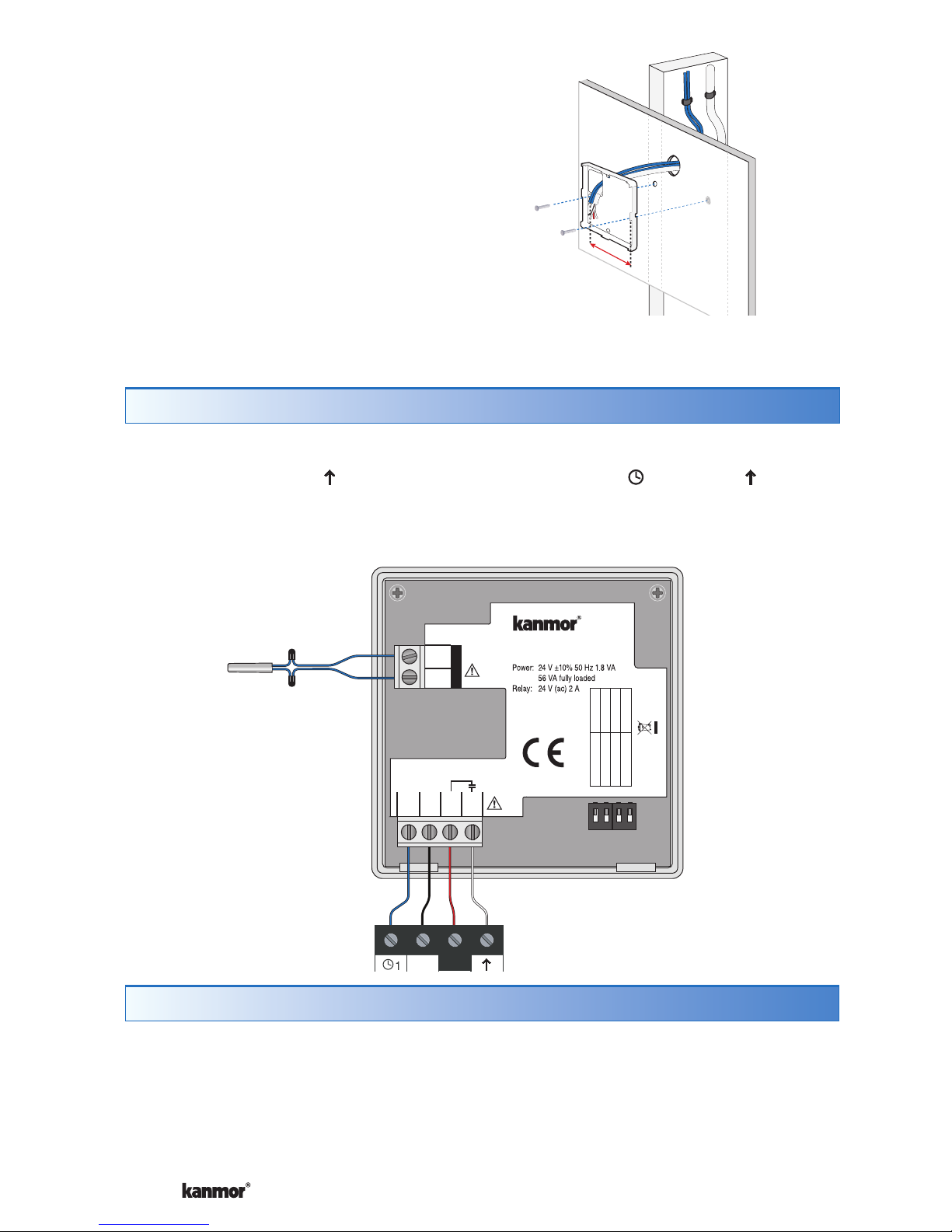
Installation
Table of Contents
Getting Started..............................2
Installation .........................................2
Caution..........................................2
Preparation....................................2
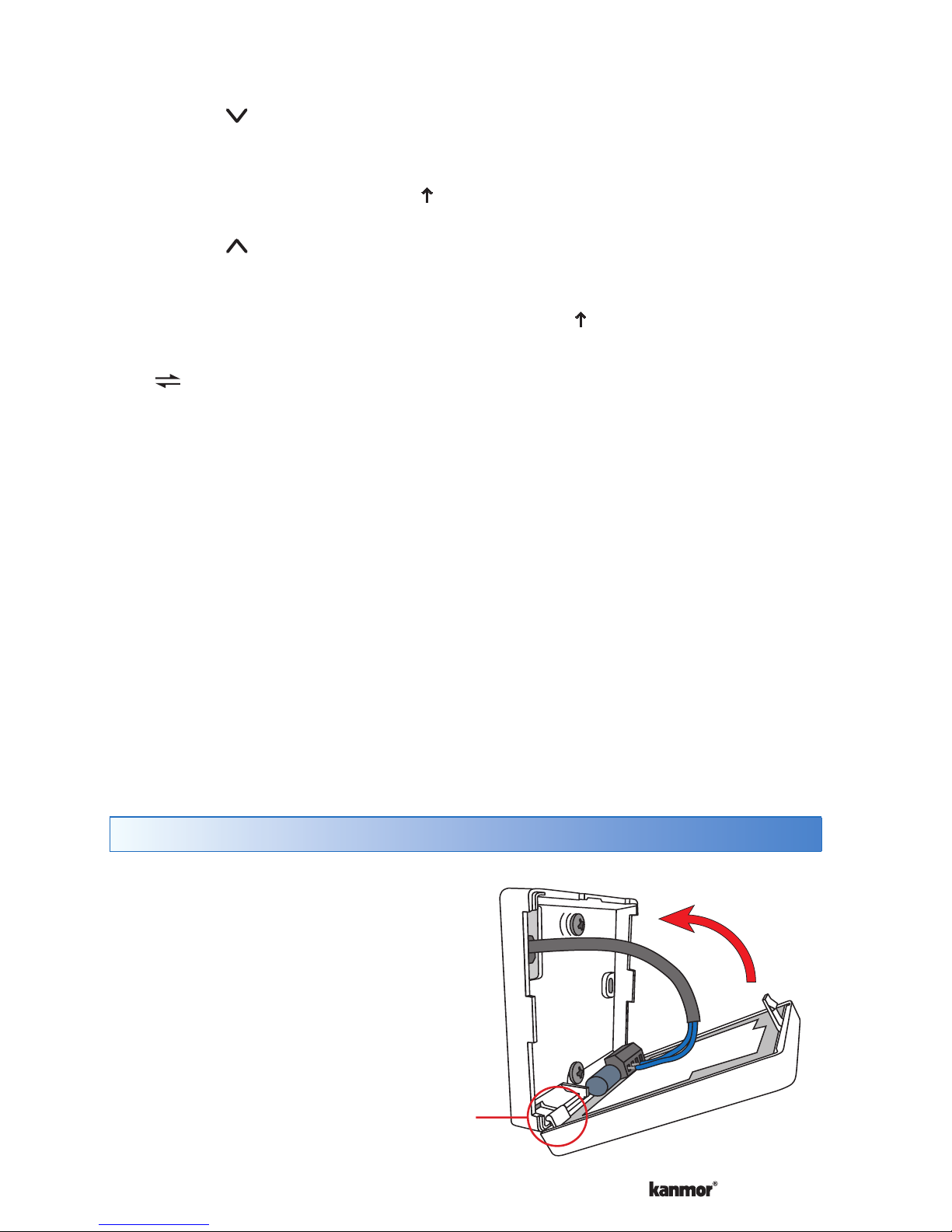
Removing The Thermostat Base...3
Mounting The Thermostat Base....3
Thermostat Wiring.........................4
Testing the Thermostat Wiring ......4
Mounting the Thermostat ..............5
Cleaning the Thermostat...............6
Switch Settings..................................6
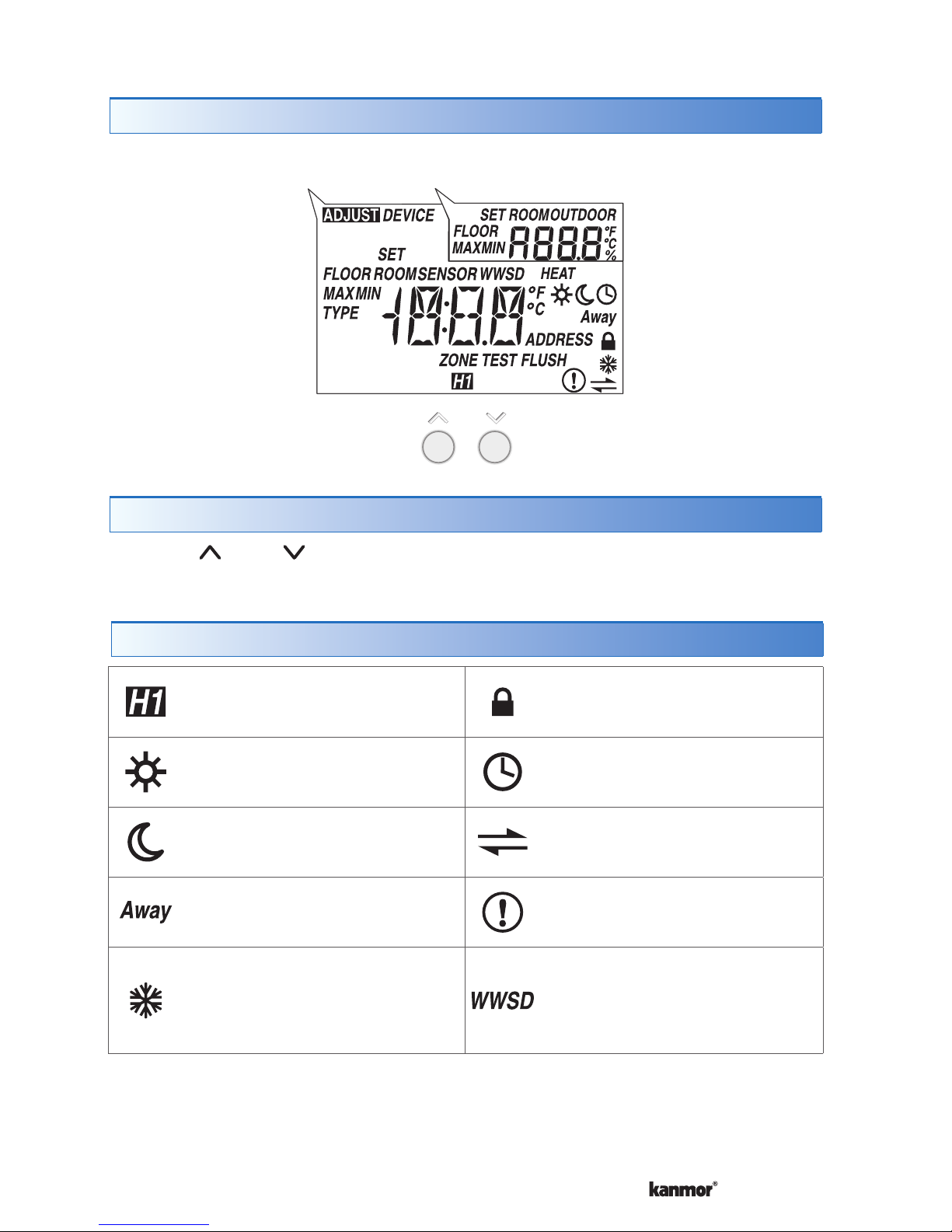
User Interface....................................7
Display...........................................7
Button Operation...........................7
Symbols Description .....................7
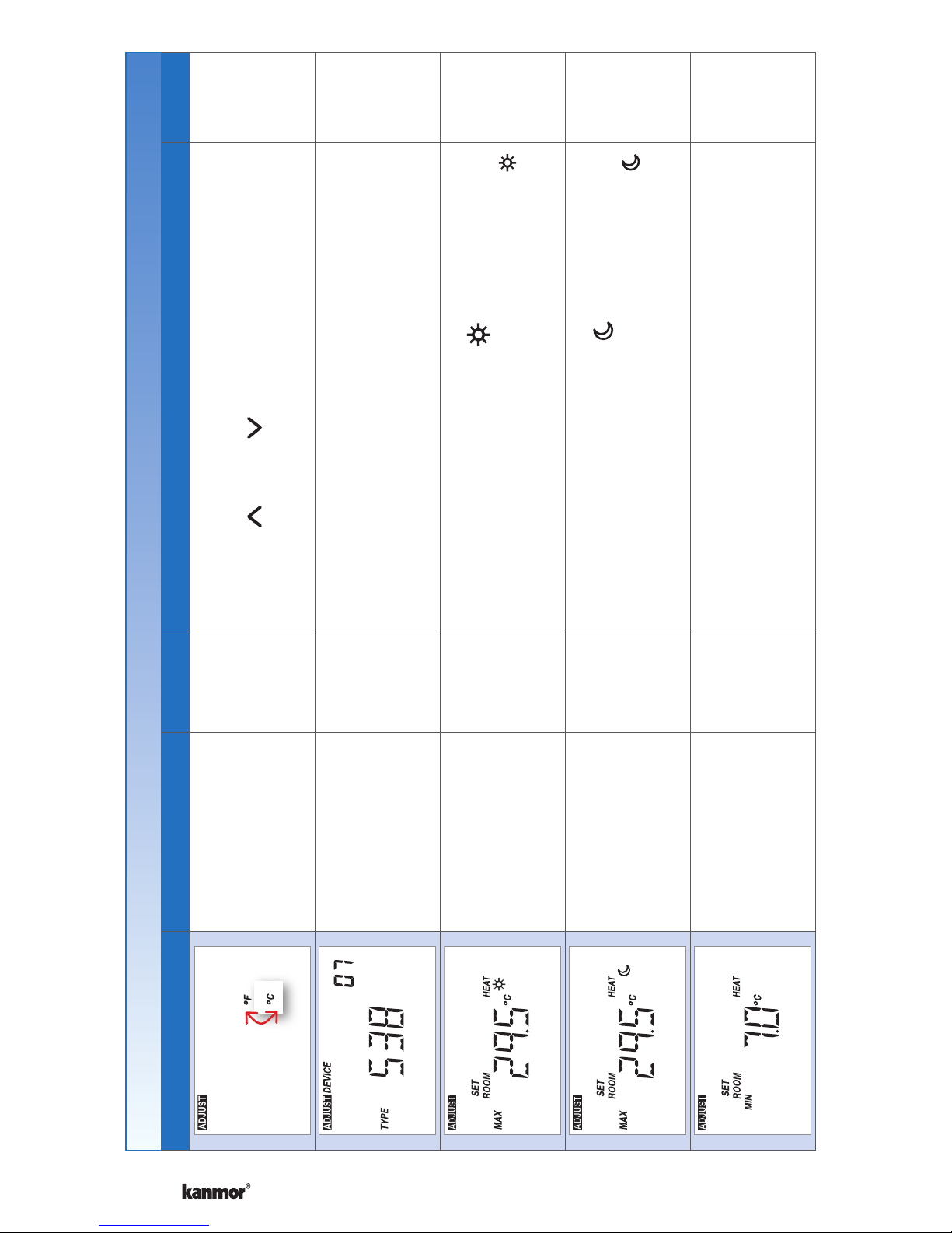
Settings ....................................8-14
Sequence of Operation....................15
Heating Operation.......................15
Cooling Group Operation ............16
Schedules ...................................17
Scenes (System Override) ..........17
Troubleshooting ...............................18
Error Messages......................18-21
Frequently Asked Questions .......22
Job Record..................................23
Technical Data.............................23
Limited Warranty and Product
Return Procedure........................24
Caution
Improper installation and operation of this control could result in damage to the
equipment and possibly even personal injury or death. It is your responsibility
to ensure that this control is safely installed according to all applicable codes and
standards. This electronic control is not intended for use as a primary limit control.
Other controls that are intended and certified as safety limits must be placed into
the control circuit.