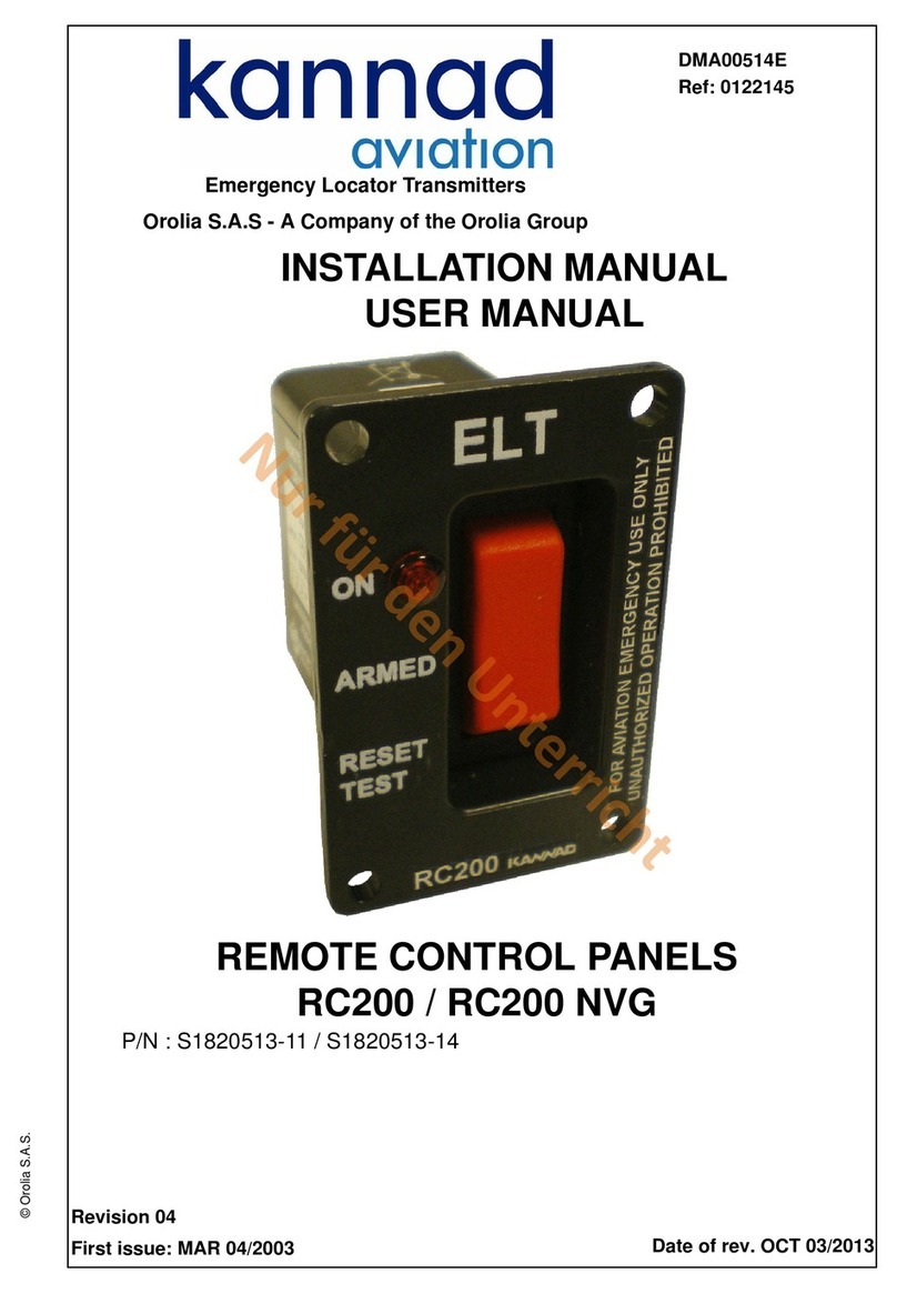
Kannad AF INTEGRA User manual

DOC09078D
Ref. 0146257D
TP PAGE : 1
Date of rev.: JUN 20/2013
Revision 03
First issue: OCT 20/2010
Orolia S.A.S. - A Company of the Orolia Group
Emergency Locator Transmitters
OPERATION MANUAL
AF INTEGRA / AF-H INTEGRA ELT
With built-in GPS & Integral Antenna
© Orolia S.A.S. : This document is the property of Orolia S.A.S. and contains proprietary and confidential information.
The document is loaned on the express condition that neither the document itself nor the information contained therein shall be disclosed without the express consent of Orolia S.A.S. and that the information
shall not be used by the recipient without prior written acceptance by Orolia S.A.S.. Furthermore, the document shall be returned immediately to Orolia S.A.S. upon request.

Users are kindly requested to notify Orolia S.A.S of any discrepancy,
omission or error found in this manual.
Please report to our customer support:
E-mail: support.sar@orolia.com
Tel.: +33 (0)2 97 02 49 00

OPERATION MANUAL
AF INTEGRA / AF-H INTEGRA ELT
RECORD OF REVISIONS
ROR PAGE: 1
JUN 20/2013
REV. Nb REVISION DATE INSERTION DATE BY
00 OCT 20/2010 OCT 20/2010 J.S.
01 MAY 09/2011 MAY 09/2011 J.S.
02 JAN 31/2012 JAN 31/2012 J.S.
03 JUN 20/2013 JUN 20/2013 J.S.

OPERATION MANUAL
AF INTEGRA / AF-H INTEGRA ELT
RECORD OF REVISIONS
ROR PAGE: 2
JUN 20/2013
PAGE INTENTIONALLY LEFT BLANK

OPERATION MANUAL
AF INTEGRA / AF-H INTEGRA ELT
LIST OF EFFECTIVE PAGES
LEP PAGE: 1
JUN 20/2013
SUBJECT PAGE DATE
Title Page
TP 1 JUN 20/2013
Record of Revisions
ROR 1 JUN 20/2013
ROR 2 JUN 20/2013
List of Effective Pages
LEP 1 JUN 20/2013
LEP 2 JUN 20/2013
LEP 3 JUN 20/2013
LEP 4 JUN 20/2013
Table of Contents
TOC 1 JUN 20/2013
TOC 2 JUN 20/2013
Introduction
INTRO 1 JUN 20/2013
INTRO 2 JUN 20/2013
System Overview
1 JUN 20/2013
2 JUN 20/2013
3 JUN 20/2013
4 JUN 20/2013
5 JUN 20/2013
6 JUN 20/2013
System Functional Description and Operation
101 JUN 20/2013
102 JUN 20/2013

OPERATION MANUAL
AF INTEGRA / AF-H INTEGRA ELT
LIST OF EFFECTIVE PAGES
LEP PAGE: 2
JUN 20/2013
103 JUN 20/2013
104 JUN 20/2013
105 JUN 20/2013
106 JUN 20/2013
107 JUN 20/2013
108 JUN 20/2013
109 JUN 20/2013
110 JUN 20/2013
111 JUN 20/2013
112 JUN 20/2013
Installation / Removal
201 JUN 20/2013
202 JUN 20/2013
203 JUN 20/2013
204 JUN 20/2013
205 JUN 20/2013
206 JUN 20/2013
207 JUN 20/2013
208 JUN 20/2013
Check
301 JUN 20/2013
302 JUN 20/2013
303 JUN 20/2013
304 JUN 20/2013
Troubleshooting
401 JUN 20/2013
SUBJECT PAGE DATE

OPERATION MANUAL
AF INTEGRA / AF-H INTEGRA ELT
LIST OF EFFECTIVE PAGES
LEP PAGE: 3
JUN 20/2013
402 JUN 20/2013
Schematics and Diagrams 501 JUN 20/2013
502 JUN 20/2013
503 JUN 20/2013
504 JUN 20/2013
Servicing
601 JUN 20/2013
602 JUN 20/2013
SUBJECT PAGE DATE

OPERATION MANUAL
AF INTEGRA / AF-H INTEGRA ELT
LIST OF EFFECTIVE PAGES
LEP PAGE: 4
JUN 20/2013
PAGE INTENTIONALLY LEFT BLANK

OPERATION MANUAL
AF INTEGRA / AF-H INTEGRA ELT
TABLE OF CONTENTS
TOC PAGE: 1
JUN 20/2013
INTRODUCTION ..................................................................................... 1
WARRANTY ........................................................................................... 2
Scope .................................................................................................... 2
Exclusion ............................................................................................... 2
SYSTEM OVERVIEW ............................................................................. 1
COSPAS-SARSAT System ................................................................... 1
Description .............................................................................................................1
World coverage with the COSPAS-SARSAT system ............................................2
Operation ...............................................................................................................2
Environmental improvements of ELTs ...................................................................2
KANNAD 406 ELT System Presentation .............................................. 3
LINE REPLACEABLE UNITS ............................................................... 5
Transmitter ............................................................................................................ 5
Bracket ..................................................................................................................6
External antenna ................................................................................................... 6
SYSTEM FUNCTIONAL DESCRIPTION AND OPERATION ..... 101
Transmitter Functional Description ................................................... 101
Transmission ..................................................................................................... 101
Controls & Connectors ...................................................................................... 101
Working mode information ................................................................................. 102
Off ................................................................................................................... 102
Self-Test .......................................................................................................... 102
Armed .............................................................................................................. 103
On ................................................................................................................... 103
VSWR Switch function (External / Integral antenna) ......................................... 104
GPS Strategy ..................................................................................................... 104
Basic Installation or portable use (without NAV Interface equipment) ............104
Installation including a NAV Interface equipment (Dongle IF GPS RS232) ....105
Autonomy .......................................................................................................... 105
Electrical interfaces ........................................................................................... 106
Transmitter Technical Specifications ................................................................. 107
Equipment limitations ........................................................................ 108
Activation ........................................................................................... 108
Standby mode for automatic activation .............................................................. 108
Manual activation ............................................................................................... 108
Off ..................................................................................................... 109
Self-Test ............................................................................................ 109
Compatibility list ................................................................................ 110
Mounting brackets ............................................................................................. 110
Remote control panels (RCP) ............................................................................ 110
Outside buzzer .................................................................................................. 110
DIN-12 connector or programming dongles ....................................................... 110
OPERATION MANUAL
AF INTEGRA / AF-H INTEGRA ELT
TABLE OF CONTENTS
TOC PAGE: 2
JUN 20/2013
External antennas ............................................................................................. 111
INSTALLATION / REMOVAL ............................................................. 201
Registration ....................................................................................... 201
General .............................................................................................................. 201
Registration in USA ........................................................................................... 201
Registration in Canada ...................................................................................... 202
Programming .................................................................................... 203
"Pin programming" option .................................................................................. 203
ELT transmitter installation procedure .............................................. 204
ELT transmitter Connection .............................................................. 206
First power up ................................................................................... 206
Removal ............................................................................................ 207
CHECK ............................................................................................... 301
Self-test ............................................................................................. 301
Periodicity .......................................................................................................... 301
Self-test procedure ............................................................................................ 301
Operational tests ............................................................................... 302
ELT operational tests ........................................................................................ 302
Test of transmitted signals ................................................................................ 302
406 MHz Transmission tests ........................................................................... 302
121.5 MHz Transmission tests ........................................................................ 303
TROUBLESHOOTING ........................................................................ 401
General ............................................................................................. 401
Faults on Self-test ............................................................................. 401
3+1 flashes ..................................................................................................... 401
3+2 flashes ..................................................................................................... 401
3+3 flashes ..................................................................................................... 401
3+4 flashes ..................................................................................................... 401
3+5 flashes ..................................................................................................... 401
3+6 flashes ..................................................................................................... 401
SCHEMATICS & DIAGRAMS ............................................................ 501
Outline dimensions and weight with mounting bracket AF-COMPACT 501
Outline dimensions and weight with universal mounting bracket ...... 502
AF INTEGRA / AF INTEGRA (ER), axis of installation ..................... 503
AF-H INTEGRA / AF-H INTEGRA (ER), axis of installation ............. 504
SERVICING ................................................................................. 601
Maintenance Schedule ..................................................................... 601
Periodic inspection ............................................................................................ 601
Battery replacement .......................................................................................... 601
Battery replacement requirements .................................................... 602

OPERATION MANUAL
AF INTEGRA / AF-H INTEGRA ELT
PAGE INTRO 1
JUN 20/2013
INTRODUCTION
INTEGRA ELTs are an extension of the range of KANNAD ELTs. The
development of this type of ELTs is based on the improvement of safety of
flights either for light aircraft, business aircraft or commercial aviation.
The safety of flights is strengthened thanks to a built-in GPS giving a more
accurate position transmitted within minutes following the distress and an
Integral Antenna which may replace the external antenna in case on
unavailability of this last one.
AF
(1)
INTEGRA is designed for fixed wing aircraft or helicopters, AF-H
INTEGRA is designed for flat installation on board helicopters only.
The AF INTEGRA (ER) and AF-H INTEGRA (ER) ELTs are evolutions of AF
INTEGRA and AF-H INTEGRA ELTs. The main evolution consists in the
extension to -40°C of temperature range.
The instructions in this manual provide the information necessary for the
installation and the operation of AF INTEGRA, AF-H INTEGRA, AF INTEGRA
(ER) and AF-H INTEGRA (ER) ELTs.
Servicing instructions of ELT are normally performed by shop personnel. For
detailed instructions , refer to Service & Support section of Kannad Aviation
Website.
For the initial installation, please refer to Initial Installation Manual supplied with
AF INTEGRA, AF-H INTEGRA, AF INTEGRA (ER) and AF-H INTEGRA (ER)
ELTs.
FOR REGULATORY REQUIREMENTS, PLEASE CONSULT YOUR
NATIONAL AVIATION AUTHORITY.
NOTE: (1) AF for Automatic Fixed

OPERATION MANUAL
AF INTEGRA / AF-H INTEGRA ELT
PAGE INTRO 2
JUN 20/2013
WARRANTY
1. Scope
The equipment is warranted against all material or manufacturing defect for a
period of two years from the date of installation on the aircraft or thirty months
from the date of shipment from Orolia S.A.S. facilities whichever occur first.
Work carried out under the warranty shall not have the effect of extending the
warranty period.
In respect of this warranty, after a defect has been noted by our services, the
sole obligation incumbent upon us shall be the repair of the equipment or the
element identified as being defective by our services or possibly its
replacement free of charge, to the exclusion of all compensation or damages.
This warranty covers the cost of parts and labour in our factories.
The cost of transportation of the equipment replaced or repaired are the
purchaser's exclusive responsibility.
The risks shall be borne by the purchaser.
2. Exclusion
Defects and deterioration caused by natural wear of the product or by external
accident (poor maintenance, abnormal conditions of use, etc.) or by
modification of the equipment and tools not recommended nor specified by our
company, are excluded from the warranty.
Also the warranty shall not cover visible defects which the purchaser wouldn't
have formally notified Orolia S.A.S within 48 hours of receipt of the equipment.

OPERATION MANUAL
AF INTEGRA / AF-H INTEGRA ELT
PAGE: 1
JUN 20/2013
SYSTEM OVERVIEW
1. COSPAS-SARSAT System
A. Description
Launched in the early eighties by the four founder countries (Canada, France,
Russia, USA), the COSPAS-SARSAT system provides satellite aid to search
and rescue (SAR) operations for maritime, aeronautical and terrestrial vehicles
anywhere in the world.
It uses distress beacons fitted on mobiles and a constellation of LEO and GEO
satellites which relay and process the 406 MHz signal to ground stations (LUT)
where the beacon positions are determined with a precision of less than 2 NM
with the Doppler effect.
Several types of beacons are designed to match the various applications of the
COSPAS-SARSAT system:
• EPIRB (Emergency Position Indicating Radio Beacon) for maritime
applications.
• ELT (Emergency Locator Transmitter) for aeronautical applications.
• PLB (Personal Locator Beacon) for land expeditions.
Figure 1: COSPAS-SARSAT System

OPERATION MANUAL
AF INTEGRA / AF-H INTEGRA ELT
PAGE: 2
JUN 20/2013
B. World coverage with the COSPAS-SARSAT system
The major improvement is the use of the COSPAS-SARSAT system for
processing aeronautical emergencies.
The 406 MHz transmission carries digital data which enable the identification
of the aircraft in distress and facilitate SAR operation (type of the aircraft,
number of passengers, type of emergency).
The 406 MHz message is transmitted to the COSPAS-SARSAT satellites. This
message is downloaded to one of the 64 ground stations (44 LEOLUTs and 20
GEOLUTS).
The aircraft is located by Doppler effect by the LEO satellites with a precision
better than 2 NM (4 km) at any point of the earth.
Thanks to the built-in GPS receiver, the position (accuracy typically about 60
meters) will be transmitted by the ELT within minutes following the distress.
The 121.5 MHz frequency is no more processed by COSPAS-SARSAT system
but is still used by SAR services for homing in the final stage of rescue
operations.
C. Operation
In the event of a crash, the ELT activates automatically and transmits a sweep
tone on 121.5 MHz and the 406 MHz signal.
In a crash, a G-Switch (shock detector) turns the ELT "ON" when the ELT is
subjected to an important change of velocity (or deceleration).
Activation may also be accomplished by means of a Remote Control Panel
(RCP) from the cockpit or directly from a switch of the ELT’s front panel.
In the event the external antenna is unavailable due to the crash, the
integral antenna will replace it to transmit the 406 MHz signal to the
Cospas-Sarsat satellites.
Note: The integral antenna has not been tested and approved by Cospas-
Sarsat.
D. Environmental improvements of ELTs
The certification of an ELT includes a range of severe mechanical tests:
• resistance to flame;
• impact and crush tests;
• resistance up to 500 G shocks;
• watertightness;
• anti-deflagration;
• extreme temperatures .

OPERATION MANUAL
AF INTEGRA / AF-H INTEGRA ELT
PAGE: 3
JUN 20/2013
2. KANNAD 406 ELT System Presentation
AF INTEGRA and AF-H INTEGRA belong to the AF type of ELTs which are
permanently attached to an aircraft. AF INTEGRA and AF-INTEGRA (ER) are
designed to be installed on fixed wing aircraft or helicopters. AF-H INTEGRA
and AF-H INTEGRA (ER) are designed for flat installation on board helicopters
only.
The INTEGRA ELT system (Refer to Section Figure 2: ELT system description
page 4) is composed of:
1. the ELT transmitter:
• P/N S1851501-01 for AF INTEGRA (ER) or,
• P/N S1851501-02 for AF INTEGRA or,
• P/N S1852501-01 for AF-H INTEGRA (ER) or,
• P/N S1852501-02 for AF-H INTEGRA
2. a mounting bracket (P/N S1840502-01 or S1840502-02);
3. an external whip, rod or blade antenna;
4. A remote control panel
(1)
;
5. a DIN-12 connector, programming dongle or dongle IF GPS RS232
(2)
when the optional RCP is connected.
6. an outside buzzer (optional).
Note: (1) The RCP is optional only if the commands and controls of the
ELT are reachable and visible from the pilot seated position.
(RTCA DO-204A):
"Equipment control and indicator installed for in-flight use shall be readily
accessible from the cockpit crew position. The cockpit crew shall have an
unobstructed view of visual indicator when in the normal seated position."
Note: (2) GPS/NAV Interface with an on board RS232 GPS.
For details of approved part number of INTEGRA ELT system, Refer to Section
6. Compatibility list page 110.
The transmitter and bracket are installed in the aircraft near the tail. The
external antenna is mounted on the fuselage near the tail. The remote control
panel is installed in the cockpit and connected to the ELT with a DIN-12
connector or a programming dongle and a 2, 3, or 4-wire bundle (not supplied)

OPERATION MANUAL
AF INTEGRA / AF-H INTEGRA ELT
PAGE: 4
JUN 20/2013
Figure 2: ELT system description
Note: Data position from an on board RS232 GPS only available if a dongle IF
GPS RS232 (5) is connected instead of programming dongle (5) or DIN-12
connector (5).

OPERATION MANUAL
AF INTEGRA / AF-H INTEGRA ELT
PAGE: 5
JUN 20/2013
3. LINE REPLACEABLE UNITS
A. Transmitter
The AF INTEGRA and AF-H INTEGRA are ELTs designed to be installed
onboard aircraft to transmit a distress signal on frequencies:
• 406 MHz (COSPAS-SARSAT frequency) for precise pinpointing and
identification of the aircraft in distress.
• 121.5 MHz used for homing in the final stages of the rescue operations.
The AF INTEGRA and AF-H INTEGRA are certified as Automatic Fixed (AF)
ELTs with the approved external antennas.
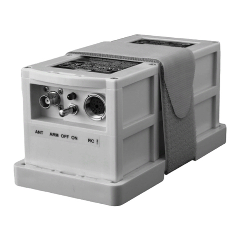
The housing of AF INTEGRA and AF-H INTEGRA transmitters are made of
molded plastic with excellent mechanical resistance.
The ELT housing is designed with no sharp edges.
Figure 3: ELT Transmitter

OPERATION MANUAL
AF INTEGRA / AF-H INTEGRA ELT
PAGE: 6
JUN 20/2013
B. Bracket
The bracket installed near the tail is designed to fix the ELT with a Velcro®
strap. This enables quick removal of the ELT for maintenance or exchange.
Figure 4: ELT Transmitter with Mounting Bracket
The transmitter may be installed on its standard mounting bracket
(P/N S1840502-01) or on an Universal Mounting Bracket (P/N S1840502-02)
to re-use existing drilling for retrofit (Refer to DOC09081, Initial Installation
Manual for drilling masks and outline dimensions of these brackets).
C. External antenna
Only approved antennas may be installed (Refer to Section 6.
Compatibility list page 110).
Connection to the ELT will be carried out with a 50 Ohm coaxial cable (RG58
for example) ended with a male BNC connector.
IMPORTANT NOTICE: Orolia S.A.S. recommends a cable with radio
electric properties similar or better to those of a RG58 cable.
Note: the 50 Ohm coaxial and the male BNC connector are not supplied

OPERATION MANUAL
AF INTEGRA / AF-H INTEGRA ELT
PAGE: 101
JUN 20/2013
SYSTEM FUNCTIONAL DESCRIPTION AND OPERATION
1. Transmitter Functional Description
A. Transmission
The transmitter can be activated either automatically when the crash occurs
(thanks to a shock sensor) or manually (thanks to a switch on the transmitter
itself or on a RCP).
The transmitter is designed to transmit on two frequencies (121.5 and 406
MHz). The 121.5 Mhz is mainly used for homing in thefinal stages of the rescue
operations. The 406 MHz frequency is used by the COSPAS-SARSAT
satellites for precise pinpointing and identification of the aircraft in distress.
Once activated, the transmitter operates continuously on 121.5 MHz.
During operations, a digital message is transmitted on 406.037 MHz every 50
seconds.
B. Controls & Connectors
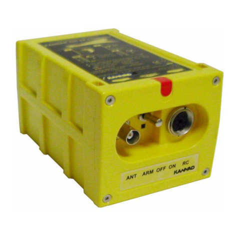
The following controls are to be found on the ELT front panel (from left to right):
1. 3-position switch ARM/OFF/ON;
2. Visual indicator (red);
3. DIN 12 socket for connection to an optional Remote Control Panel, a
programming dongle, dongle IF GPS RS232 or a programming
equipment;
4. BNC connector for the external antenna.
Figure 1: Front Panel

OPERATION MANUAL
AF INTEGRA / AF-H INTEGRA ELT
PAGE: 102
JUN 20/2013
The red light gives an indication on the working mode of the beacon:
• after the self test:
- a series of short flashes indicates the self test failed;
- one long flash indicates a correct self test;
• in operating mode:
- periodic flashes during 121.5 transmission;
- long flash during 406 transmission.
A buzzer gives audio information on the beacon working:
• continuous tone during self test;
• 1 beep every 0.7 second during 121.5 transmission;
• silence during 406 transmission.
C. Working mode information
The ELT has 4 different modes:
• Off.
• Self-test (temporary mode).
• Armed (standby mode to enable automatic activation by the shock sensor
or by an optional remote control panel).
• On (transmission).
Transmission is effective if the beacon is activated (either manually on the ELT
control panel, automatically by the shock sensor, or remotely by the "ON"
switch of an optional remote control panel when connected).
(1)Off The ELT is off when the switch is in position "OFF", no part of the ELT
is energized.
This mode must only be selected when the ELT is removed from the
aircraft or when the aircraft is parked for a long period or for
maintenance.
(2) Self-Test
The self-test mode is a temporary mode (max duration 15 sec) in which
the ELT checks the main characteristics of the transmitter (Battery
voltage, Programming...) and enables digital communication with
programming and test equipment.
This mode is selected:
• when switching from "OFF" to "ARM";
• when switching to "RESET / TEST" on an optional Remote Control
Panel (provided that the switch of the ELT is in position "ARM");
• when switching to "ON" prior to transmission.
Other manuals for AF INTEGRA
1
This manual suits for next models
1
Table of contents
Other Kannad Transmitter manuals

Kannad
Kannad 406 AF-COMPACT User manual

Kannad
Kannad 406 AF User manual

Kannad
Kannad 406 AP User manual

Kannad
Kannad SafeLink AIS SART2 User manual

Kannad
Kannad 406 AP-H User manual

Kannad
Kannad 406 AF-COMPACT Service manual

Kannad
Kannad AF INTEGRA User manual

Kannad
Kannad RC200 Guide

Kannad
Kannad 406 AF-COMPACT User manual