Motorola OMNISTAR GX2-LM1000E Series User manual

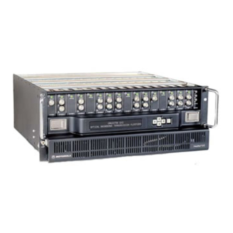
Motorola’s OmniStar GX2-LM1000E Series 1310 nm Broadcast Transmitter uses a high-power DFB laser,
an integrated low-noise preamp, and state-of-the-art predistortion and anticlipping circuitry for superior
performance.The compact, energy-efficient design allows up to 16 plug-and-play transmitter modules to
operate in the 4 RU OmniStar GX2 housing, maximizing valuable headend space. Enhanced with
PowerPC technology, LM1000E series transmitters introduce intelligence to traditional headend equip-
ment. Hot-swappable modules with Quick-Swap Module Configuration maximize in-service time by
eliminating the need for manual configuration.The wide range of optical output power is coupled with
the full complement of other OmniStar GX2 application modules, providing extreme flexibility for
network design and fiber link optimization.
DATA SHEET
BENEFITS
1 GHz bandwidth
High module density—up to 16
transmitter modules in a 4 RU
housing
High performance:
• Advanced predistortion cir-
cuitry achieves superior
CSO and CTB performance
• Integrated low-noise
preamp allows a low RF
input level
• Unique anticlipping circuitry
yields excellent BER
performance for digital data
Compatible with CWDM
networks
ROHS-compliant
Intelligent—contains a high-
performance PowerPC
microprocessor
Quick-swap capability—
replacement modules are
recognized and updated with
settings prestored by the con-
trol module
Flexible—full range of output
powers from 2 dBm to 15 dBm,
separate broadcast and narrow-
cast RF inputs, and multiple
gain modes accommodate vari-
ous system architectures
OMNISTAR®GX2
GX2-LM1000E Series 1310 nm Broadcast Transmitter
User-friendly—2 RF test points
(input and laser drive) and
CW/Video modes provide accu-
rate link optimization
Energy-efficient—designed
with advanced integrated
circuits for low power
consumption
Plug-and-play—application
modules feature blind-mate RF
connectors in the rear

The GX2-LM1000E series is a line of high-performance 1310 nm DFB laser transmitter
modules for the OmniStar®GX2 optical broadband transmission platform.
Module Features
The modules are designed for ease of use. The optical output connector is located on the
front of the module for easy cleaning and installation. The standard connector type is an
SC/APC; an E2000 connector is available as an option. The dual fans on each module are
field-replaceable, and the fan current is monitored to provide operational status.
Transmitter setup and link proofing are quick and easy. The modules are preset at the fac-
tory for optimal performance immediately on power-up. Targeted services can be easily
added using the separate high-isolation narrowcast RF input. Two front-panel RF test
points provide convenient verification of signal inputs. One test point directly monitors the
main RF input, while the other test point monitors the RF drive into the laser. Firmware is
downloadable and can be upgraded while the module remains in operation. No hardware
changes are needed. The CW/Video modes allow a link to be set up and proofed using a
CW source. When modulated signals, which have a lower average power level than CW
carriers, are applied, the microprocessor adjusts the RF drive level into the laser to match
the CW drive levels based on the operator-selected video offset. Several offset settings
are provided to match different system needs.This feature ensures that the laser is not
operating in clipping when modulated signals are applied, providing operators with a
reliable and accurate way to proof links.
Three gain modes offer greater design flexibility:
• Preset—Automatic Gain Control using factory settings for optimal laser performance
• Set—Automatic Gain Control to an RF level adjusted by the operator to optimize noise
and distortion performance based on channel loading and system requirements
• Manual—Fixed Gain to an RF level adjusted by the operator to optimize noise and
distortion performance based on channel loading and system requirements
Intelligence
The PowerPC microprocessor, the heart of every LM1000E series transmitter module,
offers sophisticated control functions along with high integration. This single-chip design
contains flash memory, random access memory, and analog/digital converters.
Manufacturing test data and all module-specific information (e.g., firmware, menu
structure, etc.) are stored in the nonvolatile memory.
Communications
Several methods are available for real-time system monitoring and control. A tri-colored
LED on each module indicates general operating status. The optional shelf door unit with
display provides monitoring and control with an alphanumeric display and simple push-but-
ton navigation. In addition, a PC interface is available through an Ethernet port on the front
of the control module. Using a standard Web browser, the graphical user interface
provides a point-and-click method for configuring the shelf. For higher-level management,
the OmniStar GX2 can be easily connected to a remote network management system
using a standard Ethernet SNMP interface.


1 GHz Loading Link Specifications
DISTORTION
Composite Triple Beat (CTB) –70 dB1
Composite Second Order (CSO) –66 dB1
Cross-Modulation (XMOD) –65 dB1
CARRIER-TO-NOISE (CNR)
All performances specified for a channel loading of 79 NTSC analog channels @ 15 dBmV/CH + 450 MHz digital loading @ –6 dBc.
Specifications are valid over the full operating temperature range of 0 °C to 50 °C.
For total optical loss that is greater than the specified output power for a given model, the CNR specifications are for additional passive loss only.
Specifications measured using a GX2-RX1000B receiver and CW carriers per SCTE standards.
1. Distortion specifications for GX2-LM1000E15* models are –69 CTB, –63 CSO, –63 XMOD.
Model
Output
Power
(Min.,
dBm)
Fiber
Length
(km)
Total Optical Loss (dB)
(Fiber + Passive Loss)
2345678910 11 12 13 14 15 16
GX2-LM1000E2 22.5 53.5 52.5 51.5
GX2-LM1000E3 35.0 54.5 53.5 52.5 51.5
GX2-LM1000E4 47. 5 54.5 53.5 52.5 51.5
GX2-LM1000E5 510.0 54.5 53.5 52.5 51.5
GX2-LM1000E6 612.5 54.5 53.5 52.5 51.5
GX2-LM1000E7 715.0 54.5 53.5 52.5 51.5
GX2-LM1000E8 817.5 54 53 52 51
GX2-LM1000E9 920.0 54 53 52 51
GX2-LM1000E10 10 22.5 54 53 52 51
GX2-LM1000E11 11 25.0 53.5 52.5 51.5 50.5
GX2-LM1000E12 12 27.5 53.5 52.5 51.5 50.5
GX2-LM1000E13 13 30.0 53.5 52.5 51.5 50.5
GX2-LM1000E14 14 32.5 53.5 52.5 51.5 50.5
GX2-LM1000E15 15 35.0 52.5 51.5 50.5

870 MHz Loading Link Specifications
DISTORTION
Composite Triple Beat (CTB) –70 dB1
Composite Second Order (CSO) –66 dB1
Cross-Modulation (XMOD) –65 dB1
CARRIER-TO-NOISE (CNR)
All performances specified for a channel loading of 79 NTSC analog channels @ 15 dBmV/CH + 320 MHz digital loading @ –6 dBc.
Specifications are valid over the full operating temperature range of 0 °C to 50 °C.
For total optical loss that is greater than the specified output power for a given model, the CNR specifications are for additional passive loss only.
Specifications measured using a GX2-RX1000B receiver and CW carriers per SCTE standards.
1. Distortion specifications for GX2-LM1000E15* models are –69 CTB, –63 CSO, –63 XMOD.
Model
Output
Power
(Min.,
dBm)
Fiber
Length
(km)
Total Optical Loss (dB)
(Fiber + Passive Loss)
2345678910 11 12 13 14 15 16
GX2-LM1000E2 22.5 54 53 52
GX2-LM1000E3 35.0 55 54 53 52
GX2-LM1000E4 47. 5 55 54 53 52
GX2-LM1000E5 510.0 55 54 53 52
GX2-LM1000E6 612.5 55 54 53 52
GX2-LM1000E7 715.0 55 54 53 52
GX2-LM1000E8 817.5 54.5 53.5 52.5 51.5
GX2-LM1000E9 920.0 54.5 53.5 52.5 51.5
GX2-LM1000E10 10 22.5 54.5 53.5 52.5 51.5
GX2-LM1000E11 11 25.0 54 53 52 51
GX2-LM1000E12 12 27.5 54 53 52 51
GX2-LM1000E13 13 30.0 54 53 52 51
GX2-LM1000E14 14 32.5 54 53 52 51
GX2-LM1000E15 15 35.0 52.8 51.8 50.8

OPTICAL SPECIFICATIONS
Optical Wavelength 1311 nm ±7 nm
Optical Output Ports One
Optical Connector Types SC/APC or E2000 with Optical Safety Shutter
Laser Shutdown Enable/Disable via Control Module
RF SPECIFICATIONS
Operational Bandwidth 47 to 1002 MHz
Broadcast Input Level 15 ±0.5 dBmV/ch (79 NTSC channels + 450 MHz digital
at –6 dBc)
Narrowcast Input Level 6 dBc above broadcast input levels
Flatness 1.5 dB max. peak to valley, 47 to 1002 MHz
RF Input Test Point –20 ±0.5 dB relative to main RF input port
RF Input Impedance 75 Ω
RF Input Return Loss (broadcast and narrowcast) 16 dB min., 47 to 1002 MHz
Narrowcast to Main RF Input Isolation 50 dB min., 47 to 1002 MHz
GENERAL SPECIFICATIONS
Dimensions 1.0 in W x 5.9 in H x 15.0 in D
(2.5 cm x 15.0 cm x 38.0 cm)
Weight 2.0 lb (1.0 kg)
Mounting GX2-HSG* Equipment Shelf
RF Connector Types
Input F-type (using G-to-F adapter on chassis)
Test points F-type
Operating Temperature Range 0 °C to 50 °C (32 °F to 122 °F)
Storage Temperature Range –40 °F to 176 °F (–40 °C to 80 °C)
Power Consumption 12 W typical
Eye Protection Optical Safety Shutter
Visual Interface Tri-colored module status LED
Data/Control Interface Serial Peripheral Interface (SPI) to Control Module
**Indicates optical output power. See Carrier-to-Noise table for all available models.
ORDERING INFORMATION
Model Number Description
GX2-LM1000E**-R Broadcast Transmitter, SC/APC Optical Connector
GX2-LM1000E**/E-R Broadcast Transmitter, E2000 Optical Connector
MOTOROLA and the Stylized M Logo are registered in the U.S. Patent and Trademark Office. All other product
or service names are the property of their respective owners. © Motorola, Inc. 2007. All rights reserved.
535220-001-a 5398 - 0807 - 0K
Motorola, Inc. 101 Tournament Drive, Horsham, Pennsylvania 19044 U.S.A.
www.motorola.com
This manual suits for next models
14
Table of contents
Other Motorola Transmitter manuals

Motorola
Motorola T505 - MOTOROKR - Speaker Phone User manual

Motorola
Motorola DSP56011 User manual

Motorola
Motorola CP 140 User manual

Motorola
Motorola CB200-U User manual

Motorola
Motorola GP360 Series User manual

Motorola
Motorola GX2 EA1000C Series User manual

Motorola
Motorola EX600 User manual

Motorola
Motorola SG4-DRT-2X Assembly instructions

Motorola
Motorola Omnistar GX2-DM1000B10/CH Series User manual

Motorola
Motorola SG2-DRT-3X Assembly instructions