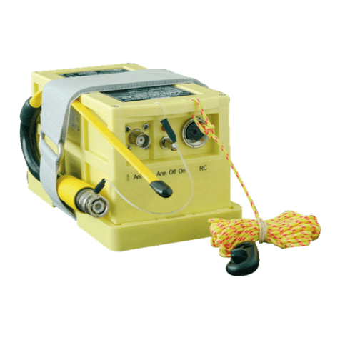
Kannad 406 AF User manual

Emergency Locator Transmitters
DMA174N
Ref. 0139162N
TP PAGE : 1
Date of rev. JUN 23/2008
Revision 12
First issue: SEP 02/1999
INSTALLATION MANUAL
OPERATION MANUAL
INSPECTION LOG
KANNAD 406 AF / AF-H / AF (6D)
P/N : S1821502-02 KANNAD 406 AF transmitter
P/N : S1822502-02 KANNAD 406 AF-H transmitter
P/N : S1821502-06 KANNAD 406 AF(6D) transmitter
P/N : S1820511-01 Mounting bracket, 1 strap
© KANNAD: This document is the property of KANNAD and contains proprietary and confidential information.
The document is loaned on the express condition that neither the document itself nor the information contained therein shall be disclosed without the express consent of KANNAD and that the information shall
not be used by the recipient without prior written acceptance by kannad Furthermore, the document shall be returned immediately to KANNAD upon request.

INSTALLATION MANUAL OPERATION MANUAL INSPECTION LOG
KANNAD 406 AF / AF-H / AF (6D)
RECORD OF REVISIONS
ROR PAGE: 1
JUN 23/2008
REV. Nb REVISION DATE INSERTION DATE BY
01
02
03
04
05
06 OCT 14/2003 OCT 14/2003 J. S.
07 NOV 19/2003 NOV 19/2003 J. S.
08 APR 23/2004 APR 23/2004 J. S.
09 JAN 24/2005 JAN 24/2005 J. S
10 JUN 27/2005 JUN 27/2005 J. S.
11 FEB 01/2008 FEB 01/2008 J. S.
12 JUN 23/2008 JUN 23/2008 J.S

INSTALLATION MANUAL OPERATION MANUAL INSPECTION LOG
KANNAD 406 AF / AF-H / AF (6D)
RECORD OF REVISIONS
ROR PAGE: 2
JUN 23/2008
PAGE INTENTIONALLY LEFT BLANK

INSTALLATION MANUAL OPERATION MANUAL INSPECTION LOG
KANNAD 406 AF / AF-H / AF (6D)
LIST OF EFFECTIVE PAGES
LEP PAGE: 1
JUN 23/2008
SUBJECT PAGE DATE
Title Page
TP 1 JUN 23/2008
Record of Revisions
ROR 1 JUN 23/2008
ROR 2 JUN 23/2008
List of Effective Pages
LEP 1 JUN 23/2008
LEP 2 JUN 23/2008
Table of Contents
TOC 1 JUN 23/2008
TOC 2 JUN 23/2008
TOC 3 JUN 23/2008
TOC 4 JUN 23/2008
Introduction
INTRO 1 JUN 23/2008
INTRO 2 JUN 23/2008
System Overview
1 JUN 23/2008
2 JUN 23/2008
3 JUN 23/2008
4 JUN 23/2008
5 JUN 23/2008
6 JUN 23/2008
System Functional Description and Operation
101 JUN 23/2008
102 JUN 23/2008

INSTALLATION MANUAL OPERATION MANUAL INSPECTION LOG
KANNAD 406 AF / AF-H / AF (6D)
LIST OF EFFECTIVE PAGES
LEP PAGE: 2
JUN 23/2008
103 JUN 23/2008
104 JUN 23/2008
105 JUN 23/2008
106 JUN 23/2008
107 JUN 23/2008
108 JUN 23/2008
Installation / Removal
201 JUN 23/2008
202 JUN 23/2008
203 JUN 23/2008
204 JUN 23/2008
205 JUN 23/2008
206 JUN 23/2008
207 JUN 23/2008
208 JUN 23/2008
209 JUN 23/2008
210 JUN 23/2008
Check
301 JUN 23/2008
302 JUN 23/2008
303 JUN 23/2008
304 JUN 23/2008
Troubleshooting
401 JUN 23/2008
SUBJECT PAGE DATE

INSTALLATION MANUAL OPERATION MANUAL INSPECTION LOG
KANNAD 406 AF / AF-H / AF (6D)
LIST OF EFFECTIVE PAGES
LEP PAGE: 3
JUN 23/2008
402 JUN 23/2008
Schematics and Diagrams 501 JUN 23/2008
502 JUN 23/2008
503 JUN 23/2008
504 JUN 23/2008
Servicing
601 JUN 23/2008
602 JUN 23/2008
SUBJECT PAGE DATE

INSTALLATION MANUAL OPERATION MANUAL INSPECTION LOG
KANNAD 406 AF / AF-H / AF (6D)
LIST OF EFFECTIVE PAGES
LEP PAGE: 4
JUN 23/2008
PAGE INTENTIONALLY LEFT BLANK

INSTALLATION MANUAL OPERATION MANUAL INSPECTION LOG
KANNAD 406 AF / AF-H / AF (6D)
TABLE OF CONTENTS
TOC PAGE: 1
JUN 23/2008
INTRODUCTION ..................................................................................... 1
SYSTEM OVERVIEW ............................................................................. 1
COSPAS-SARSAT System ................................................................... 1
Description .............................................................................................................1
World coverage with the COSPAS-SARSAT system ............................................2
Environmental improvements of ELTs ...................................................................2
G-Switch (shock detectors) ....................................................................................2
KANNAD 406 ELTs Presentation .......................................................... 3
LINE REPLACEABLE UNITS ............................................................... 4
Transmitter ............................................................................................................4
Bracket ..................................................................................................................4
Remote Control Panel ...........................................................................................4
Outside antenna ....................................................................................................4
Design features ..................................................................................... 5
General ..................................................................................................................5
Mechanical design .................................................................................................5
SYSTEM FUNCTIONAL DESCRIPTION AND OPERATION ............ 101
Transmitter ........................................................................................ 101
Controls ............................................................................................. 102
Working mode information ................................................................ 103
Off ...................................................................................................................... 103
Self-Test ............................................................................................................103
Armed ................................................................................................................104
On ...................................................................................................................... 104
Autonomy .......................................................................................... 105
Electrical characteristics .................................................................... 106
Electrical interface ............................................................................................. 106
Technical Specifications .................................................................... 107
Activation ........................................................................................... 108
Standby mode for automatic activation ..............................................................108
Manual activation ...............................................................................................108
Reset ................................................................................................. 108
Manual reset ...................................................................................................... 108
Reset with Remote Control Panel ...................................................................... 108
Self-Test ............................................................................................ 108
INSTALLATION / REMOVAL ............................................................. 201
RTCA / FAR recommendations ......................................................... 201
Registration and Programming ......................................................... 202

INSTALLATION MANUAL OPERATION MANUAL INSPECTION LOG
KANNAD 406 AF / AF-H / AF (6D)
TABLE OF CONTENTS
TOC PAGE: 2
JUN 23/2008
Pin programming option .................................................................................... 202
Installation ......................................................................................... 204
KANNAD 406 AF installation ............................................................................. 206
Fixed wings ..................................................................................................... 206
Helicopters ...................................................................................................... 206
KANNAD 406 AF-H installation ......................................................................... 207
KANNAD 406 AF (6D) installation ..................................................................... 208
First power up ................................................................................... 208
Removal ............................................................................................ 209
CHECK ............................................................................................... 301
Self-test ............................................................................................. 301
Periodicity .......................................................................................................... 301
Self-test procedure ............................................................................................ 301
ELT operational tests ........................................................................ 302
Installation without programming dongle ........................................................... 302
Installation with programming dongle ................................................................ 302
RCP operational tests ....................................................................... 303
406 and 121.5 MHz transmission test ............................................... 304
ELT-Antenna link ............................................................................................... 304
406 MHz ............................................................................................................ 304
121.5 MHz ......................................................................................................... 304
TROUBLESHOOTING ........................................................................ 401
General ............................................................................................. 401
Faults on Self-test ............................................................................. 401
Visual indicator .................................................................................................. 401
3+1 flashes ..................................................................................................... 401
3+2 flashes ..................................................................................................... 401
3+3 flashes ..................................................................................................... 401
3+4 flashes ..................................................................................................... 401
Other faults detected ......................................................................... 401
Buzzer ............................................................................................................... 401
Buzzer does not operate ................................................................................. 401
Buzzer operates permanently when ELT in ARM mode ................................. 401
SCHEMATICS & DIAGRAMS ............................................................ 501
Outline Dimensions ........................................................................... 501
Drilling Mask ..................................................................................... 502
Wiring ................................................................................................ 503
SERVICING ........................................................................................ 601
Maintenance Schedule ..................................................................... 601
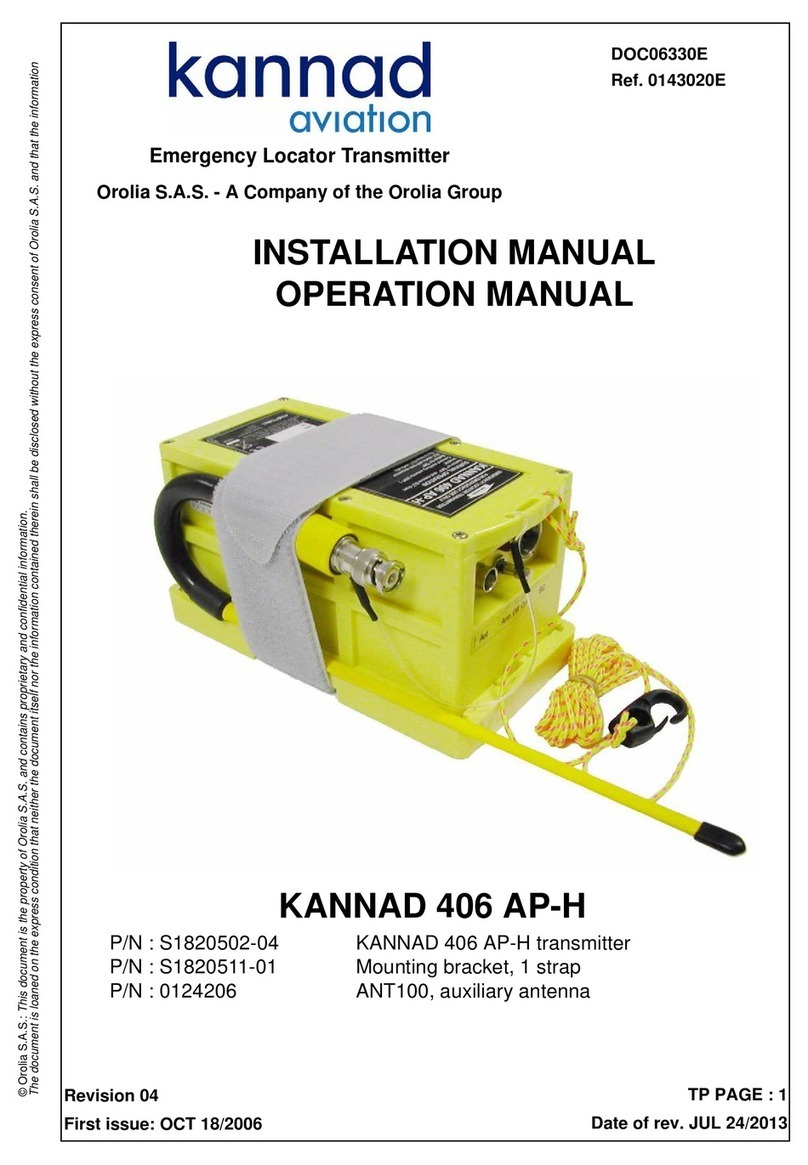
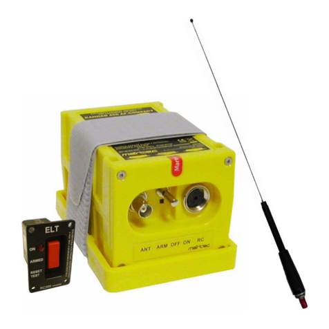
INSTALLATION MANUAL OPERATION MANUAL INSPECTION LOG
KANNAD 406 AF / AF-H / AF (6D)
TABLE OF CONTENTS
TOC PAGE: 3
JUN 23/2008
Periodic inspection ............................................................................................ 601
Every 6 years .................................................................................................... 601
Battery replacement .......................................................................................... 602

INSTALLATION MANUAL OPERATION MANUAL INSPECTION LOG
KANNAD 406 AF / AF-H / AF (6D)
TABLE OF CONTENTS
TOC PAGE: 4
JUN 23/2008
PAGE INTENTIONALLY LEFT BLANK

INSTALLATION MANUAL OPERATION MANUAL INSPECTION LOG
KANNAD 406 AF / AF-H / AF (6D)
PAGE INTRO 1
JUN 23/2008
INTRODUCTION
The instructions in this manual provide the information necessary for the
installation and the operation of KANNAD 406 AF, AF-H and AF (6D) ELTs.
Servicing instructions are normally performed by shop personnel.
For servicing and maintenance instructions, refer to CMM 25-63-01.
For regulatory requirements, please consult your national aviation authority.

INSTALLATION MANUAL OPERATION MANUAL INSPECTION LOG
KANNAD 406 AF / AF-H / AF (6D)
PAGE INTRO 2
JUN 23/2008
PAGE INTENTIONALLY LEFT BLANK

INSTALLATION MANUAL OPERATION MANUAL INSPECTION LOG
KANNAD 406 AF / AF-H / AF (6D)
PAGE: 1
JUN 23/2008
SYSTEM OVERVIEW
1. COSPAS-SARSAT System
A. Description
Launched in the early eighties by the four founder countries (Canada, France,
Russia, USA), the COSPAS-SARSAT system provides satellite aid to search
and rescue (SAR) operations for maritime, aeronautical and terrestrial vehicles
anywhere in the world.
It uses distress beacons fitted on mobiles and a constellation of LEO and GEO
satellites which relay the 121.5 / 243 MHz signals and process the 406 MHz
signal to ground stations (LUT) where the beacon positions are determined
(with a precision of 10 NM with 121.5 / 243 signals and less than 2 NM with 406
signals).
Several types of beacons are designed to match the various applications of the
COSPAS-SARSAT system:
• EPIRB (Emergency Position Indicating Radio Beacon) for maritime
applications.
• ELT (Emergency Locator Transmitter) for aeronautical applications.
• PLB (Personal Locator Beacon) for land expeditions.
Figure 1: COSPAS-SARSAT System

INSTALLATION MANUAL OPERATION MANUAL INSPECTION LOG
KANNAD 406 AF / AF-H / AF (6D)
PAGE: 2
JUN 23/2008
B. World coverage with the COSPAS-SARSAT system
The major improvement is the use of the COSPAS-SARSAT system for
processing aeronautical emergencies.
The difference with the 121.5 / 243 MHz is that the 406 MHz transmission
carries digital data which enable the identification of the aircraft in distress and
facilitate SAR operation (type of the aircraft, number of passengers, type of
emergency).
The 406 MHz message is transmitted to the COSPAS-SARSAT satellites. This
message is downloaded to one of the 64 ground stations (44 LEOLUTs and 20
GEOLUTS).
The aircraft is located by Doppler effect by the LEO satellites with a precision
better than 2 NM (4 km) at any point of the earth.
C. Environmental improvements of ELTs
The certification of an ELT includes a range of severe mechanical tests:
• resistance to flame;
• impact and crush tests;
• resistance to 100 G and 500 G shocks;
• watertightness;
• antideflagration;
• extreme temperatures (-20°C to 55°C for more than 48 hours).
D. G-Switch (shock detectors)
The shock detectors currently equipping automatic ELTs are the cause of a
large number of false alarms. Major work has consisted in studying aircraft
crashes (study made by the " Crash Research Institute ") and evaluating the
acceleration amplitudes involved. As a consequence, G-Switch specifications
have been modified to optimize the accuracy of the crash detection.

INSTALLATION MANUAL OPERATION MANUAL INSPECTION LOG
KANNAD 406 AF / AF-H / AF (6D)
PAGE: 3
JUN 23/2008
2. KANNAD 406 ELTs Presentation
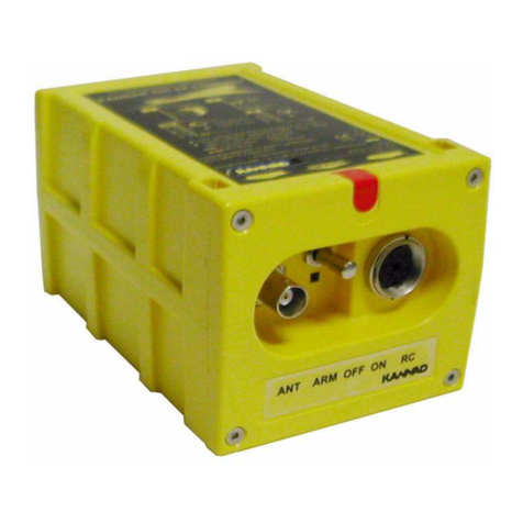
The KANNAD 406 AF / AF-H / AF (6D) are composed of:
1. a transmitter;
2. a mounting bracket;
3. a remote control panel (mandatory if ELT controls are not available from
the pilot’s position, refer to RTCA/DO-183, RTCA/DO-204, EUROCAE
ED-62);
4. an outside antenna;
5. a "Programming Dongle" for pin-programming function (option);
6. CS144 Interface Module (option).
The transmitter, bracket, Programming Dongle and CS144 Interface Module
are installed in the aircraft near the tail. The outside antenna is mounted on the
fuselage near the tail. The remote control panel is installed in the cockpit and
connected to the ELT with a 4 or 5 wire bundle.
Figure 2: ELT system description
The KANNAD 406 AF and AF(6D) are designed to be installed on fixed wing
aircraft or helicopters.
The KANNAD 406 AF-H is to be installed only on helicopters.

INSTALLATION MANUAL OPERATION MANUAL INSPECTION LOG
KANNAD 406 AF / AF-H / AF (6D)
PAGE: 4
JUN 23/2008
3. LINE REPLACEABLE UNITS
A. Transmitter
The KANNAD 406 AF / AF-H / AF (6D) is an ELT designed to be installed on
board aircraft to transmit a distress signal on 3 frequencies:
• 406 MHz (COSPAS-SARSAT frequency) for precise pinpointing and
identification of the aircraft in distress.
• 121.5 and 243 MHz used for homing in the final stages of the rescue
operations.
The KANNAD 406 AF / AF-H / AF (6D) are certified as Automatic Fixed (AF)
ELTs and only work with a three-frequency outside antenna.
B. Bracket
The bracket installed near the tail is designed to fix the ELT with a Velcro®
strap. This enables quick removal of the ELT for maintenance or exchange.
C. Remote Control Panel
A remote control panel is available for installation in the cockpit in order to
enable the pilot to monitor and control the ELT status.
The following controls are to be found on the panel:
• 3-position switch (ON, ARMED, RESET&TEST);
• red or amber visual indicator;
• beeper (on certain versions).
The remote control panel is connected to the ELT via a 4 or 5-wire cable
equipped with a "Programming Dongle" or a DIN 12 connector on the ELT side
and the connector corresponding to the Remote Control Panel version on the
other side.
D. Outside antenna
The outside antenna, also installed near the tail, can be either rod or blade type
according to aircraft speed.
Connection to the ELT will be carried out with a 50 Ohm coaxial cable (RG58
for example) ended with a BNC connector.
IMPORTANT NOTICE: KANNAD recommends a cable with radio electric
properties similar or better to those of a RG58 cable.

INSTALLATION MANUAL OPERATION MANUAL INSPECTION LOG
KANNAD 406 AF / AF-H / AF (6D)
PAGE: 5
JUN 23/2008
4. Design features
A. General
The KANNAD 406 AF / AF-H / AF (6D) belong to the AF type of ELTs which are
permanently attached to an aircraft.
B. Mechanical design
The KANNAD 406 AF / AF-H / AF (6D) are made of moulded plastic with
excellent mechanical resistance (ASA/PC, light yellow colour).
The housing is designed with no sharp edges.
Figure 3: KANNAD 406 AF / AF-H / AF (6D) with mounting bracket

INSTALLATION MANUAL OPERATION MANUAL INSPECTION LOG
KANNAD 406 AF / AF-H / AF (6D)
PAGE: 6
JUN 23/2008
PAGE INTENTIONALLY LEFT BLANK
This manual suits for next models
5
Table of contents
Other Kannad Transmitter manuals

Kannad
Kannad SafeLink AIS SART2 User manual

Kannad
Kannad 406 AP User manual

Kannad
Kannad 406 AP-H User manual

Kannad
Kannad AF INTEGRA User manual

Kannad
Kannad AF INTEGRA User manual

Kannad
Kannad 406 AF-COMPACT User manual

Kannad
Kannad 406 AF-COMPACT Service manual

Kannad
Kannad 406 AF-COMPACT User manual

Kannad
Kannad RC200 Guide