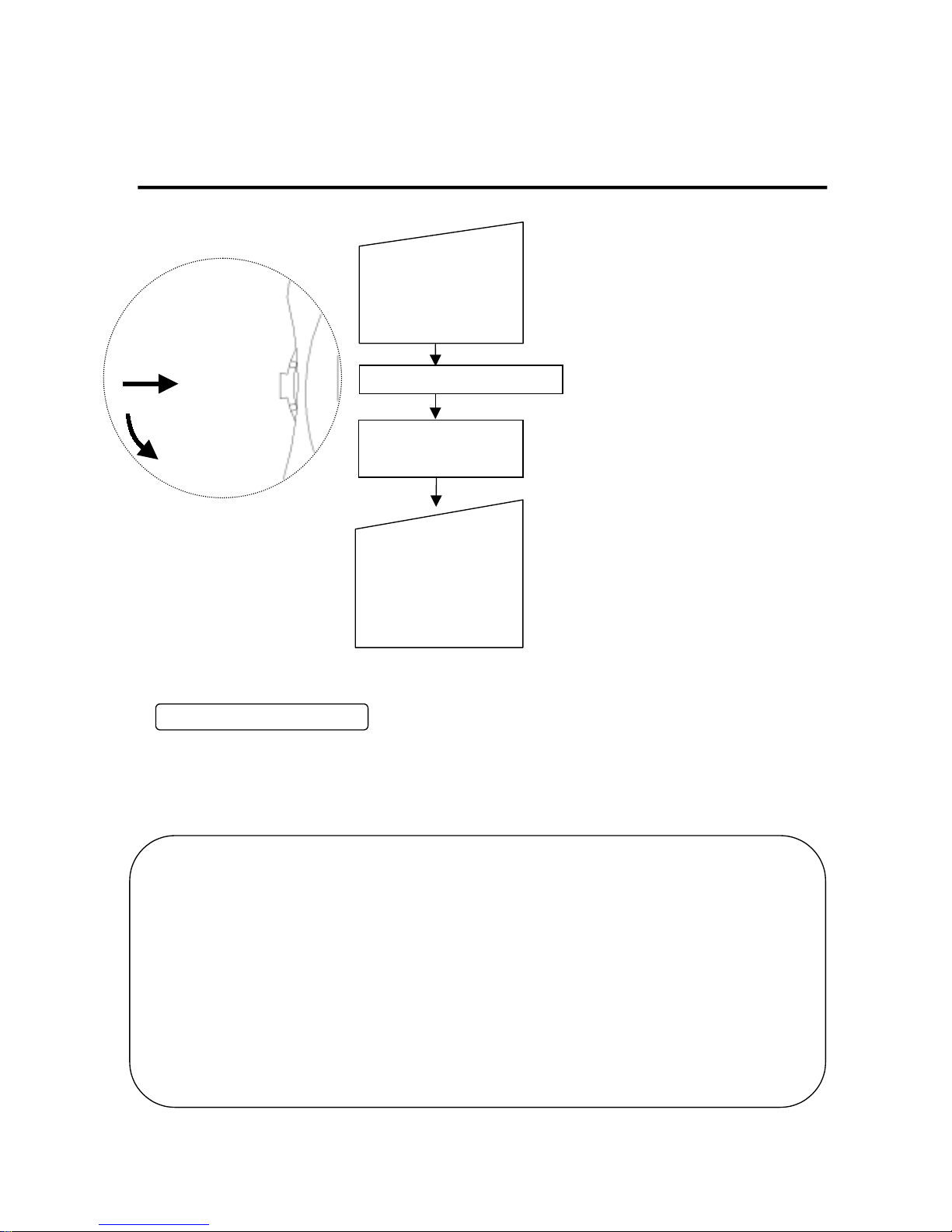
Kanomax 6841 User manual

Thermo-Hygrometer
Model 6841
Read this manual carefully and understand the warnings before using this instrument.
Kanomax Japan, Inc.
Keep this manual in a safe place for your quick reference.
Operation Manual

Thank you for purchasing this Kanomax product.
Please use this instrument properly by reading the instruction
manual and following the warning instructions.

Contents
Name and function of parts (Main body) 1
Names and Functions of Parts (Probe) 2
Preparation for Measurement 3
Measurement 4
BatteryIndicator 5
UnitChange 5
Specifications 6
Troubleshooting 7
WarrantyandService 8

Before Operation
In this operation manual, we define warnings and their classifications as follows.
[ Classifications ]
Danger :To prevent injury and death.
Warnings in this classification indicate danger that may result in injury
anddeathifnotobserved.
Caution :To prevent damage to the product.
Warningsinthisclassificationindicate risks of damage to the product
andperformancefailure.
[ Symbols ]
△symbol indicates a condition that requires caution. The subject of each caution
is illustrated inside the triangle.
(Left: caution for hot surface )
symbol indicates prohibition. Do not take a prohibited action shown inside or
nearthissymbol.
( Left: Do not disassemble )
●This symbol indicates a mandatory action. A specific action is given near the
symbol.
DANGER
○ Never expose the sensor to a flammable gas.
……The heated sensor may explode or catch fire.
○ Do not disassemble or heat the batteries.
Do not throw them into fire.
……The batteries may explode.
Do not use near
flammable gas
Explosive

DANGER
○ Do not drop or hit the instrument.
……It may cause damage and malfunctioning.
Do not drop or hit
○ Do not disassemble, modify, or repair the instrument.
……It may cause a short circuit and malfunction.
Donotdisassembleormodify
○ Do not hold the instrument by its probe cable.
…… The instrument may be damaged.
Do not hold probe cable
○ Set batteries in the correct direction. Check polarity.
……Setting the batteries in the wrong direction
may cause leakage and contaminate the Insert correctly
instrument.
○ Do not wipe the instrument with a solvent.
……The body may deform or deteriorate. Use soft dry cloth to
remove stains. If stains persist, soak the cloth in a neutral
detergent and wipe the instrument with the soft cloth.
Do not use solvents such as thinner and benzine.
Donotusesolvent
○ Keep the sensor clean.
Dust attached to the sensor may affect accuracy.
Keepclean
−
+

−1−
Name and function of parts (Main body)
<Side> <Front> <Back>
< Power/Function Switch >
* Power/Function Switch is to be pressed and
slid down.
① For turn on/off power, press the switch and hold
for more than one second until the LCD is turned on.
② For functions, slide the switch down to change
temperature and humidity parameters.
Humidity → Temperature → Humidity
* Sliding the switch upward has no function.
Approx. 120 mm (4.7”)
Approx. 34 mm (1.3”)Approx. 60 mm (2.4”)
Power/Function Switch
Battery Case
Display
①Push and hold
for more than one
second.
②Slide down to change
between temperature and
humidity.

−2−
Names and Functions of Parts (Probe)
* Humidity and temperature
sensors are built in.
Sensor
Grip Approx. φ19 mm (0.75”)
Cable Length Approx. 1,500 mm (59”)
Approx.φ3.3mm (0.13”)
Approx. 170 mm (6.7”)

−3−
Preparation for Measurement
−Set batteries-
< Battery Case on the Back >
♦Use 4 pieces of AA batteries.
♦Make sure to turn off the power before replacing batteries.
♦If Ni-Cd batteries are used, charge them on an appropriate charger.
+
‑
‑
‑
‑
+
+
+
①Slide the cover of
the battery case
down along the rail.
②When it stops, pull up
the cover.
③Insert batteries in the
correct direction. Check
polarity.
④Put the cover back by
reversing the steps
①
and
②
.
* When closing the battery case,
do not try to hook the cover,
or the cover may be damaged.
Make sure to slide the cover
on the rail.
12
34

−4−
Measurement
* The instrument starts up in the humidity
humidity measurement mode automatically.
automatically.tomatically.
Measuring Humidity
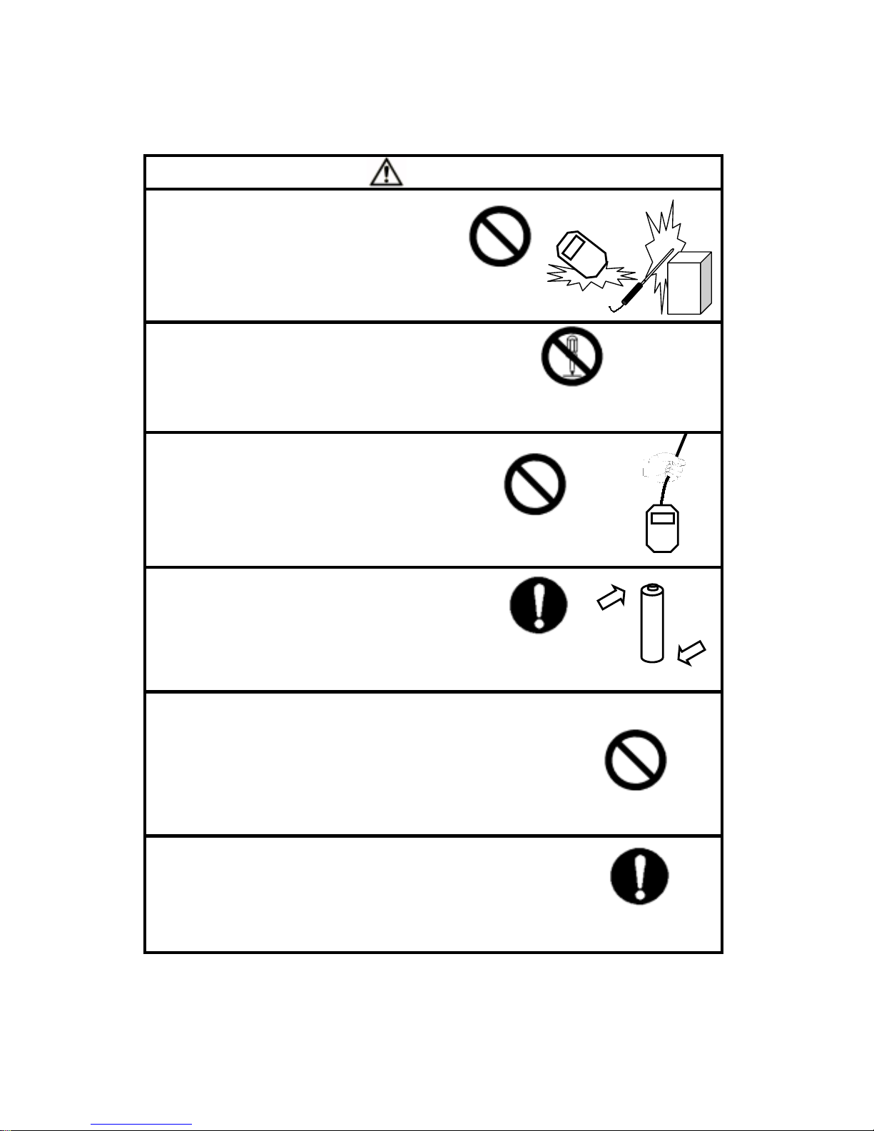
Using this instrument in environment under extremely high humidity or rapidly changing temperature may
cause condensation on the surface of the sensor. If condensation occurs, dry the sensor by leaving the
probe in environment under less than 40% RH for more than 24 hours.
――Comparison with Assmann Psychrometer ――
The humidity measurement function of Thermo-Hygrometer is strictly calibrated and traceable to
Japanese national standards carried by Japan Electric Meters Inspection Corporation (JEMIC),
thereby ensuring high accuracy.
Thermo-Hygrometer is an electronic hygrometer, which is known to have greater stability and
shorter response time compared to conventional Assmann psychrometers. Electronic hygrometers
are also independent from external conditions, while Assmann psychrometers are easily affected
by factors such as dust, dew, and how the gauze is wrapped.
For more information on proper handling of Assmann psychrometer, please refer to the Japanese
Industrial Standards (JIS-Z8806 Method of Measuring Humidity) or its alternative standards that apply.
②TEMP/HUMIDITY
①ON/OFF (Press and
hold for more than
one second)
All indications are displayed.
Humidity
measurement mode
Turn on power by
pressing and holding
the switch for more
than one second.
Slide down the switch
to change between
temperature and
humidity measurement
modes.

−5−
Battery Indicator
◎Remaining battery life is indicated as follows.
Good OK Replace batteries. LCD shuts down.
(Indicator blinks) (Indicator blinks)
♦The guaranteed functional range is more than 4.0V.
♦If the voltage falls below 4.0V, the LCD will shut down. Turn off the power switch.
♦If Ni-Cd batteries are used, charge them before the indicator shows the 4.0 to 4.3V range.
Unit Change
◎Temperature units can be changed between Celsius
and Fahrenheit with a dip switch in the battery case.
※SW2 is not used.
Units
1 2
OFF
More than 4.6V Less than 4.0V
4.3V to 4.0V
4.6V to 4.3V
1
SW No.
℃
゜F
OFF
ON
(factry default)

−6−
Specifications
Model 6841
Measuring Object Temperature and Humidity under clean air
Temperature -20 to 45℃ (-4 to 113 ゚F)
Measuring
Range Humidity 5 to 95% RH
Temperature ±0.5℃ (±1 ゚F)
Accuracy Humidity ±3% RH
Temperature 0.1℃(0.1 ゚F)
Resolution Humidity 0.1% RH
Response Time 30 seconds
Function (1) Battery indicator
(2) Unit change between Celsius and Fahrenheit with dip switch
Dimensions
Probe: Approx. φ19 x 170 mm (0.75”×6.7”)
Probe Cable: Approx. φ3.3 mm x 1.5 m (0.13”×4.9”)
Main Body: Approx. 60(W) x 120(L) x 34(D) mm (2.4”x 4.7”x 1.3”)
Power Four AA batteries
(Mn, Alkali, or Ni-Cd…use appropriate charger for Ni-Cd
batteries)
Battery Life Approx. 45 hours with alkali batteries
Probe -20 to 45℃ (-4 to 113 ゚F)
Operating
Environment Main Body 5 to 40℃ (41 to 104 ゚F)
Storage Environment -10 to 50℃ (14 to 122 ゚F)
Weight Approx. 180 g (6.3 oz.)
Standard Accessories 4 pieces of AA batteries (for test use)
1 piece of Operation manual (this manual)
* Batteries included in the package are intended for test use. When they are depleted, replace them with
new ones for accurate measurement.

−7−
Troubleshooting
Please check the following items before requesting repair.
①Problems during Normal Use
Symptom Possible Cause Solution
Batteries are depleted. Replace with new batteries.
Batteries are inserted in the
wrong way. Insert the batteries correctly.
Power is not turned on
(LCD does not display).
Battery terminals are unclean. Clean the terminals.
Out of the range. Measure within the range.
Humidity sensor is damaged. Contact a local distributor.
Humidity reading is set to
99.9% RH, or humidity
reading does not change. Probe cable is damaged. Contact a local distributor.
Out of the range. Measure within the range.
Temperature sensor is damaged. Contact a local distributor.
Temperature reading is set
To 48.0℃ or temperature
reading does not change.
.Probe cable is damaged. Contact a local distributor.
Batteries are depleted. Replace with new batteries.
Battery Indicator blinks. Battery terminals are unclean. Clean the terminals.
Different unit Unit setting has been changed. Change the unit with the dip switch
in the battery case.
②Problems during Battery Replacement
Symptom Possible Cause Solution
Power is not turned on. Batteries were replaced when
the power was on. Remove all batteries and insert
them again.

−8−
Warranty and Service
< Warranty >
♦Kanomax products are delivered after inspection in accordance with the Kanomax warranty and
quality standards. If any malfunctioning is found as a result of production failure or damage during
shipment, the Kanomax warranty is applicable.
The warranty period is 12 months from the date of delivery unless otherwise noted.
The warranty does not apply to the following cases.
(1) Use of parts or supplies other than Kanomax sold, which cause damage to this product.
(2) Loss of damage to this product due to abuse, mishandling, improper packaging by the owner,
alteration, accident, electrical current fluctuations, failure to follow operating or environmental
instructions prescribed in the operation manual provided by Kanomax, or service performed by
other than Kanomax.
<Service>
♦Whenever this product malfunctions, check Troubleshooting and identify the possible causes.
♦Repair parts are stored for the minimum of five years after the production is discontinued. The repair
parts storage period is considered as the period during which we are able to provide repair services.
For more information, please contact your local Kanomax sales office or distributor with the following
information.
When you contact us…
◇Product Name : Thermo-Hygrometer
◇Model No. 6841
◇Serial No. xxxxxx
◇Purchase Date Month and Year
◇Symptom Detail
Table of contents