Kanomax 6332 User manual

Operation Manual
AIR FLOW TRANSDUCER
MODEL 6332 / 6332D
Please read this manual carefully and understand the warnings
described in this manual before operating the product.
Keep this manual handy for ready reference
KANOMAX JAPAN, INC.
0
8
00
3
20
.
0
3

Thank you for purchasing a product of Kanomax, Inc.
Please read this operation manual carefully and operate the instrument
appropriately by following the instructions given in this manual.

Component List
■Standard
Item Model Remarks
Airflow Transducer
Main Unit (Without Display)
6332 -
Airflow Transducer
Main Unit (W
ith Display)
6332D -
■Probe & Cable (Sold Separately)
Item Model Remarks
Air Velocity Probe
0962-00 Uni-directional
0963-00
0965-00
(With Horn)
Omni-directional (Spherical)
0965-01
(Without Horn)
0965-03
(I
-
Type)
Mini-temperature-compensation-s
ensor integrated type
Omni-directional (Spherical)
0965-04
(L
-
Type)
0965-07
(I
-
Type)
Mini-temperature-compensation-s
ensor independent type
Omni-directional (Spherical)
0965-08
(L
-
Type)
0965-09
(Length: 100mm)
Omni-directional (Spherical)
0965-10
(Length: 400mm)
Probe Cable
1504-02 Length: 2m
1504-03 Length: 5m
1504-04 Length: 10m
1504-05 Length: 20m
1504-06 Length: 30m
*Main unit, probe, and probe cable are necessary to measure air velocity.
■Optional Accessory
Item Model Remarks
AC Adapter 6332-02 IN: 100-240V
OUT: DC 12V 0.5A
Ring Guard 1500-03 For 0965-00 / 0965-21
Ring Guard 6521-31 For 0965-31
Compression Fitting 0964-03 / 0964-04 For 0965-00 / 0965-01
0965
-
09 / 0965
-
10
Compression Fitting 0203-02 For 0963-00

Important Safety Information
In this operation manual, warning types and classifications are defined as follows.
[Classifications]
Danger: To Prevent Serious Injury or Death
Warnings in this classification indicate danger that may result in serious injury or
death if not observed.
Caution: To Prevent Damage to the Product
Warnings in this classification indicate risks of damage to the product that may void
the product warranty if not observed.
[Description of Symbols]
This symbol indicates a condition (including danger) that requires caution.
The subject of each caution is illustrated inside the triangle (e.g., high temperature caution
symbol shown on the left).
This symbol indicates prohibition. Do not take a prohibited action shown inside or near this
symbol (e.g., disassembly prohibition symbol shown on the left).
This symbol indicates a mandatory action. A specific action is given near the symbol.

○Never bring the probe close to a flammable gas
atmosphere.
--- The heated sensor may cause fire or explosion.
○Never disassemble, modify or repair the instrument.
--- Failure to observe the above may cause short circuit and
malfunction.
○Use the specified voltage for power supply.
--- Unspecified voltage may cause electrical shock and fire.
○Remove dust and any impurities from the terminal block.
--- The dust/impurities may cause fire.
○Do not use the instrument in a water vapor atmosphere.
--- Failure to observe the above may cause electrical shock,
fire, or damage to the sensor.
○Never touch the sensor.
--- The sensor is heated during operation. Touching the heated sensor
may cause burns, and also may damage the sensor itself.
Particular attention must be paid to spherical type sensors
(Model: 0965-00/ 0965-01/ 0965-03/ 0965-04/ 0965-07/ 0965-08)
as they are very sensitive. Please Handle with care.
Water
drops
Warning:
High Temperature /
Injury
Do not use
unspecified voltage
Danger
Do not use near
flammable gas
Do not modify /
disassemble
Prohibition
Handle Properly

○Do not use or leave the instrument in a high
temperature/humidity environment, or in a dusty
environment. The instrument must also not be left
under direct sunlight for a prolonged period.
--- The instrument may not function properly outside
the specified temperature range of 5 to 40 degrees C.
○Do not wipe the instrument with a volatile solvent.
--- The body may deform or deteriorate. Use soft dry cloth to remove stains.
If stains persist, soak the cloth in a neutral detergent and wipe the instrument
with the soft cloth.
Never use volatile solvents such as thinner and benzene.
○Do not apply strong shock to the instrument
and probe.
--- Applying strong shock may cause damage and
malfunction to the instrument and probe.
Caution
Prohibited
Installation
Prohibition
Prohibition

Table of Contents
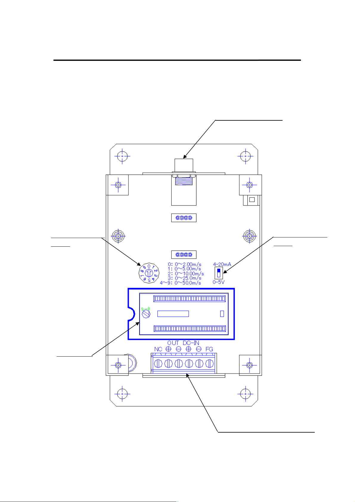
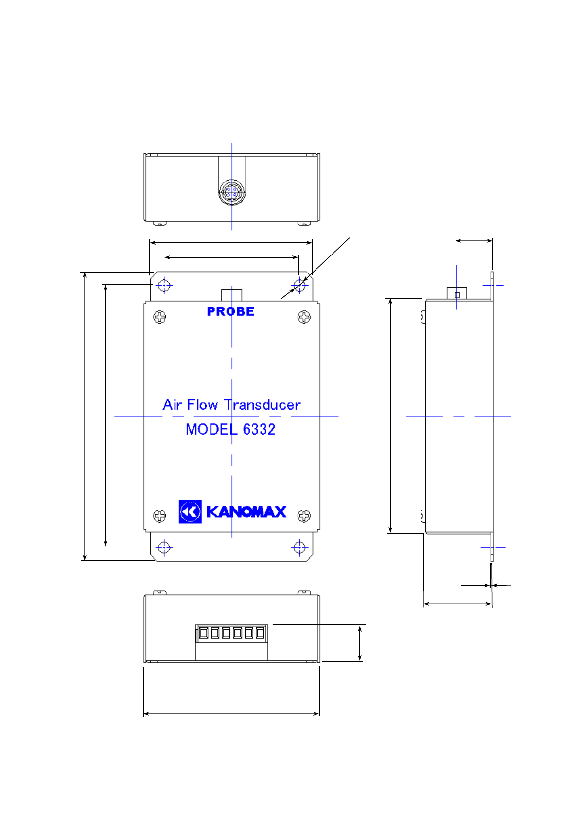
Names and Dimensions of Components........................................................ 1
System Configuration Example ..................................................................... 5
Connecting the Probe Cable to the Main Unit............................................... 6
Connecting the Probe Cable to the Probe ...................................................... 6
Installing the Data ROM................................................................................. 7
Switching Output (Setting Current/Voltage and Output Range).................. 8
Connecting Output and Power Supply......................................................... 10
Measurement Method................................................................................... 11
Optional Accessory....................................................................................... 12
Cleaning the Probe........................................................................................ 13
Specification of Main Unit ........................................................................... 14
Specification of Probes (Sold Separately) ................................................... 15
Troubleshooting ............................................................................................ 17
Product Warranty and After Service............................................................ 18
Contact Information...................................................................................... 19

1
Names and Dimensions of Components
(1) Model 6332 View inside the Case
Probe Cable Connector
Output Changeover
Switch
Range Changeover
Switch
ROM Socket
Output and Power Terminal Blocks

2
(2) Model 6332D View inside the Case
Probe Cable Connector
Output Changeover
Switch
Range Changeover
Switch
ROM Socket
Output and Power Terminal Blocks
Display Substrate

3
(3) Model 6332 View with the Case (Unit: mm)
72
60
128
116
78
17
103
16
1
30
4-φ4.5 Hole

4
(4) Model 6332D View with the Case (Unit: mm)
72
60
128
116
78
17
103
16
1
30
4-φ4.5 Hole
12 26
40

5
System Configuration Example
Probe Model 0965-01 (Sold Separately)
Probe Cable (Sold Separately)
Display (Only for 6332D)
AC Adapter (Optional)
Output Cable (Not Provided)

6
Connecting the Probe Cable to the Main Unit
<Caution>
-Make sure to cut the power supply to the main unit before connecting the probe cable (sold
separately).
-The probe cable must be wired separately from the power line.
Match the concave part of the main unit connector with the convex part of the cable connector
(4-pin), and click them in (not a screw type).
Main Unit Connector
Cable Connector (4-pin)
Connecting the Probe Cable to the Probe
<Caution>
-Make sure to cut the power supply to the main unit before connecting the probe and the
probe cable (do not supply power until both are connected).
-Match the concave part of the cable connector (5-pin) with the convex part of the probe
connector. Connect the probe and probe cable by rotating the screw portion of the
cable connector.
Cable Connector (5-pin)
(Probe: Model 0963-00 shown for reference)
A
A

7
Installing the Data ROM
<Caution>
-Make sure to cut the power supply to the main unit before installing the Data ROM.
-Install the correct Data ROM that corresponds to the probe number.
-Position the Data ROM in the correct orientation.
-After confirming that the Data ROM is properly set, use the flat-blade screwdriver to rotate
the cam 90 degrees clockwise to lock it in.
Match the notches
Data ROM
Enlarged view of cam

8
Switching Output (Setting Current/Voltage and Output Range)
<Caution>
-Make sure to cut the power supply to the main unit before switching the current/voltage
output.
-Output can be set by either voltage output (0 to 5V) or current output (4 to 20mA).
(The factory default setting is provided with current output.)
1. Current / Voltage output can be switched by the DIP switch.
2. Setting of the output range can be made by the rotary switch (setting can be changed also
while the power is supplied to the main unit).
3. Output range can be selected from the following five (5) air velocity ranges. Select the
optimum range according to the air velocity range to be measured.
No. Output Range (m/s)
Example of Output when 2m/s
Current Output (mA) Voltage Output (V)
0 0 - 2.00 20 5
1 0 - 5.00 10.4 2
2 0 -10.0 7.2 1
3 0 - 25.0 5.28 0.4
4 - 9 0 - 50.0 4.64 0.2
4
20
0
10.0
2.0
7.2
Current
Output (mA)
1
5
0
10.0
2.0
Air Velocity
(m/s)
< Relation between Air Velocity and Current/Voltage Output (for Setting No.2)
>
Voltage
Output (V)
Air Velocity
(m/s)

9
Output Changeover
DIP Switch
Range Changeover
Rotary Switch

10
Connecting Output and Power Supply
<Caution>
-Pay attention to the polarity of power supply when connecting.
-Power supply voltage must be DC 12 to 24V.
(*1) FG: Frame Ground -------- Connect to ground (earthing).
(*2) NC: No Connection ------- Connection is not required.
FG Terminal
DC-IN Term.
DC-IN Term.
OUT Term
.
FG (*1)
Power Supply Input (-)
Power Supply Input
Signal Output (-)
Signal Output (+)
<NC> (*2)
OUT Term.

11
Measurement Method
1. Using the Uni-directional Probe (Model 0962-00, 0963-00)
These probes have directivity characteristics which require the direction mark to be faced against
the airflow for measurement. When you are not sure of the airflow direction, slowly rotate the
probe in the horizontal direction, and select the point where the air velocity reading is maximum.
2. Using the Omni-directional Probe (Model 0965-00, 01/03/04/07/08/09/10)
These probes have uniform sensitivity 360 degrees horizontally. They only need to be set vertical to
the airflow direction for measurement, regardless of the orientation in the horizontal direction.
<Caution>
The probe employs a set of air velocity sensor and temperature compensation sensor to compensate
the air velocity change corresponding to the air temperature change.
In order to obtain this compensation effect, it is required that both the air velocity sensor and the
temperature compensation sensor are exposed to the airflow to be measured under the same
temperature condition. (Refer to the dimensional drawings of probes shown on page 16, 17 to
locate the air velocity sensor and the temperature compensation sensor on each probe.)
Airflow
Direction Mark
Airflow
1. Uni-directional Probe 2. Omni-directional Probe
Model 0963-00 Model 0965-01
Probe Direction

12
Optional Accessory
AC Adapter (Model 6332-02)
<Caution>
Do not connect the AC plug to the power receptacle before connecting the DC plug to the main unit.
Failure to observe the above may cause short circuit and damage to the AC adapter.
Observe the polarity and firmly insert the DC plug into the main unit as shown below. Then
connect the AC plug to the power receptacle.
* The one which is
marked is minus.
DC Plug
DC-IN Term.
DC-IN Term.
1
2
To AC Receptacle

13
Cleaning the Probe
If any impurities such as dust, soot and oil are attached to the sensor, the amount of heat that the
airflow draws from the sensor surface (heat dissipation rate) will change, thus the air velocity
reading will be affected.
The probe must be cleaned when the sensor is contaminated from use in an unclean environment.
Clean the sensor portion of the probe in an ultrasonic cleaner for approx. 10-20 sec. Do not
clean the sensor longer than required as excess cleaning will lead to sensor damage.
Use tap water (or purified water) for cleaning. The sensor portion can also be cleaned in a
vessel filled with neutral detergent diluted with water, and by stirring it in the vessel.
!) Make sure to TURN OFF the power before cleaning.
!) Dry the probe completely after cleaning. Do not use the probe before it is completely
dried.
Cleaning Method
Clean in an ultrasonic cleaner for
approx. 10-20 sec.
Do not point the sensor upwards until it is
completely dried. The water drops may get
inside the probe and cause malfunction.
! Caution !
Dry with cold air.
Other manuals for 6332
1
This manual suits for next models
1
Table of contents
Other Kanomax Transducer manuals