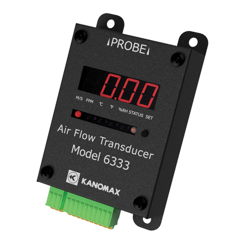
Kanomax 6333 User manual

i
Air Flow Transducer
Model 6333
User’s Manual

ii

i
List of Components
■Standard
Item
Model
Qty
Function
Main unit 6333-00 1 Measured value displaying, Analog
output
AC adapter
6333-10
1
Power source
DIN rail fixing base 6333-70 1 The base is installed.
PC software CD 6333-40 1 Air flow transducer measurement
software and its User’s Manual
■Optional Accessories
Item
Model
Function
Uni-directional air velocity probe (Flat)
0972-00
Air flow probe
Uni-directional air velocity probe (φ9)
0973-00
Air flow probe
Omni-directional air velocity probe
(Needle)
0975-00 Air flow probe
Omni-directional air velocity probe (100
mm)
0975-09 Air flow probe
Omni-directional air velocity probe (410
mm)
0975-10 Air flow probe
Heat-resistant air velocity probe (Mini,
straight type)
0976-03 Air flow probe
Heat-resistant air velocity probe (Mini,
articulating type)
0976-04 Air flow probe
Heat-resistant air velocity (Mini,
straight, temperature-compensation
sensor independent type)
0976-07 Air flow probe
Heat-resistant air velocity probe VT
(Mini, straight, temperature-
compensation sensor independent type)
0976-05 Air flow/temperature probe
Air velocity probe (Mini, straight type)
0976-13
Air flow probe
Air velocity probe (Mini, articulating
type)
0976-14 Air flow probe
Air velocity (Mini, straight, temperature-
compensation sensor independent type)
0976-17 Air flow probe
Air velocity probe VT (Mini, straight,
temperature-compensation sensor
independent type)
0976-15 Air flow/temperature probe
Omni-directional air velocity probe VT
0975-21
Air flow/temperature probe
Omni-directional air velocity probe VTH
0975-31
Air flow/temperature/humidity probe
Standard cable (0.5 m)
1580-30
For 6333 probe-to-probe connection
Standard cable (2.0 m)
1580-31
For 6333 probe-to-probe connection

ii
Standard cable (5.0 m)
1580-32
For 6333 probe-to-probe connection
Standard cable (10.0 m)
1580-33
For 6333 probe-to-probe connection
Standard cable (20.0 m)
1580-34
For 6333 probe-to-probe connection
Standard cable (40.0 m)
1580-35
For 6333 probe-to-probe connection

iii
Important Safety Information
The symbols for the warnings used in this manual are defined below.
Description of Symbols
Warning: To Prevent Serious Injury or Death
Warnings in this classification indicate risks that may result in
serious injury or death if not observed.
CAUTION: To Prevent Damage to the Product
Warnings in this classification indicate risks that may result in
damage to the product and which may void the product
warranty if not observed.
Description of Symbols
△symbol indicates a condition that requires caution (including
warning). The subject of each caution is illustrated inside the
triangle. (E.g. the high temperature caution symbol is shown
on the left.)
symbol indicates a prohibition. Do not take the prohibited
action shown inside or near this symbol. (E.g. the disassembly
prohibition symbol is shown on the left.)
●symbol indicates a mandatory action. A specific action is
given near the symbol.

iv
Warning
Always keep the probe away from areas where flammable gas
is present.
Failure to do so may cause fire and/or explosion because the
probe heats.
Never touch the air velocity element.
Direct touch to the element could cause burn injuries.
Touching to the element may also cause damage to the
element. Do not touch the element.
Do not put the battery in a fire and/or do not disassemble
and/or heat the battery.
Failure to observe the above may result in battery exploding.
Operate the instrument only on the specified supply voltage.
Failure to do so may cause electric shock, fire, or sensor
damage.
Caution
Do not use the instrument in areas where vaper is present.
Touching a water droplet to the air flow element can affect the
amount of the heat dissipation. This may cause an inaccurate
measurement and/or damage to the element.
This instrument is designed to be used in the clean air flow
without dusts and/or foreign substances.
Touching or hitting the air flow element with a foreign
substance may cause damage to the element.
Dust and/or foreign substances adhered to the air flow
element can hinder the accurate measurement.
Forbidden
High Temperature
Forbidden
Forbidden
Do Not
Touch
ExplosiveProper Handling
Forbidden

v
Do not apply an excessive force to the sensor.
If the sensor is deformed, not only maintaining the accuracy is
impossible but also the element may be broken.
Do not use or keep the instrument in hot, humid, or dusty
environment. Do not expose the instrument to direct sunlight
for a prolonged period of time.
The instrument may not function properly out of the specified
operational temperature range.
Do not subject the instrument and/or the probe to strong
shocks.
Dropping or hitting the instrument and/or the probe may
cause damage and malfunction.
Do not disassemble, modify, or attempt to repair the
instrument.
Failure to observe the above may result in a short circuit or a
malfunction.
Do not hold the probe cable to carry the instrument.
Failure to observe the above may cause damage or wire
disconnection.
When the instrument is stored for a long period of time,
remove the battery from the instrument.
Never leave a worn battery inside the instrument.
Be sure to insert the battery into the instrument in proper
polarities.
Failure to observe the above, battery leakage may occur.
Do not use volatile solvents such as thinner or benzene to
clean the instrument.
The case of the instrument may be damaged by organic
solvents. Use a soft dry cloth to remove any dirt. If this is not
effective, the user may soak the cloth in neutral detergent or
water and wipe the instrument with the cloth.
Forbidden
Forbidden
Do not disassemble
Forbidden
Forbidden
Forbidden
Proper Handling

vi
Do not allow static electrical discharge to the instrument.
Failure to observe the above may affect the measurement
value and cause damage to the instrument circuit.
Regularly check that the tip of the probe is clean.
Dust and/or foreign substances adhered to the air flow
element can hinder the accurate measurement.
To remove dust, blow it off with a blower brush for cameras or
lightly rinse with water and dry it well.
※Be sure to turn the power off to the main unit before
cleaning the air flow element.
※Never dry the probe by heat. (Failure to observe this may
cause damage to the probe.
If the instrument and the probe have been stored in a cold
place, do not bring the instrument to a warm place to avoid a
sudden temperature change.
Even when the instrument is used in the specified operating
temperature and humidity, a sudden temperature change may
cause condensation. Condensation on the sensor may cause
inaccurate measurements. If condensation occurs in the metal
part of the sensor, it becomes rusty which may cause damage
to the probe.
Do not touch the LCD screen with a sharp-pointed object or
with excessive pressure.
It may cause distortion of the screen or a malfunction.
A rapid temperature change may cause a malfunction of the
screen.
When storing the instrument, keep it in a place with an
ambient temperature of -20 to 70℃ and no condensation.
Do not dispose of the instrument as household waste.
Please note that the disposal of the instrument and batteries
should be in line with your local or national legislations.
Forbidden
Proper Handling
Forbidden
Forbidden
Electrostatic-sensitive devices
Forbidden
Prober Handling
Forbidden

vii
Table of Contents
List of Components ................................................................................................................................. i
Important Safety Information............................................................................................................ iii
Table of Contents.................................................................................................................................. vii
1. Product Appearance .......................................................................................................................... 8
1-1.Part Names and Functions
............................................................................................................... 8
1-2.External Dimension
........................................................................................................................... 9
1-3. Mounting/Removing DIN Rail Fixing Base
.................................................................................... 10
2. How to Use ........................................................................................................................................ 11
2-1.Basic Usage
...................................................................................................................................... 11
2-2.Mounting/Removing the Probe
..................................................................................................... 12
2-3.Connecting the Cable to the Terminal Block
............................................................................... 13
2-4.Connecting Power Source
.............................................................................................................. 14
2-5.Connecting Analog Output
............................................................................................................. 15
2-6.Connecting the Communication Connector
................................................................................. 16
2-7.Connecting the Probe Fixing Jig (accessory)
.............................................................................. 17
3. Various Settings ............................................................................................................................... 19
3-1.Displayed Unit Setting
.................................................................................................................... 19
3-2.Air Velocity Analog Output Setting
............................................................................................... 20
3-3.Air Temperature Analog Output Setting
...................................................................................... 21
3-4.Humidity Analog Output Setting
................................................................................................... 22
4. Specifications.................................................................................................................................... 23
5. Probe/Standard Cable (Option) Specifications ......................................................................... 24
5-1.Probe Specifications
........................................................................................................................ 24
5-2.Standard Cable Specifications
....................................................................................................... 28
6. Troubleshooting ............................................................................................................................... 29
Probe Cleaning....................................................................................................................................... 30
7. Warranty and After-Sales Services.............................................................................................. 32
8. Contact Information........................................................................................................................ 33

1. Product Appearance
1-1.Part Names and Functions
■Indicating display
Indicates measured values
■Unit indicator lamp
Indicates unit of measurement
on the display
■STATUS lamp
Green ON:Normal operation
Red ON:Probe disconnected,
Power voltage
decreasing
■
Changeover button
Switches the unit of
measurement (air
velocity/temperature/humidity).
※Only the unit of
measurement that the
probe supports will be
displayed.
■AC adapter connector
Connect the AC adapter
■Probe connector
Connect the probe
■Power input/analog output
connector
Connect power input and
analog output
■Communication connector
For communication via RS485

9
1-2.External Dimension
※The dividing terminal block is excluded.

10
1-3. Mounting/Removing DIN Rail Fixing Base
To attach the Air Flow Transducer to the DIN rail, use the DIN rail fixing base.
Mount the DIN rail fixing base on the back of the Air Flow Transducer with the provided
screws (6 EA).
To remove the DIN rail fixing base, unscrew all the screws (6 EA).

11
2. How to Use
2-1.Basic Usage
Configure the instrument in the following sequence to use.
1.Situate the probe in a measurement place and connect the probe to the instrument.
2.Connect the AC adapter connector and the AC adapter.
3.Insert the AC adapter into an outlet to power on, and the measured value will appear
on the indicating display.
- The unit indicator lamp shows the unit of the current measurement on the indicating
display.
- The changeover button enable to switch the unit of measurement item among air
velocity/temperature/humidity.
(Only measurement unit that the probe supports can be selected.)
Analog output
Once connecting the cable to the power input/analog output connector, the
measurement value of temperature, humidity and air velocity can be extracted as voltage
or current. For details, refer to 2-5. Connecting Analog Output.
Monitoring Measured Values via PC Application
Once connecting the communication connector and the PC with the USB 485 conversion
cable etc., monitoring measured values via the PC application is enabled. For details,
refer to 2-6. Connecting the Communication Connector and the User’s Manual of
Air Flow Transducer Measurement Software for Windows.
P
robe
Standard cable
6333 main unit
AC
adaoter
Output cable
RS485 cable

12
When the instrument is used in a high humidity environment for long hours or in the
abrupt temperature variation environment, the instrument can show higher measured
humidity value than the actual one. If condensation occurs, leave the probe in a place of
40%RH or lower for 24 hours to dry
2-2.Mounting/Removing the Probe
To mount the probe, face the probe connector toward the instrument connector as shown
below, insert the probe connecter into the instrument
Before connecting, be sure to check that power supply is shut off.
Be sure to remove the probe cable from power supply wiring.
To remove the probe, push and hold the release buttons of both sides of the cable connector,
and pull out the cable.
Before disconnecting, be sure to check the power supply is shut off.
When removing the probe, cut power supply.

13
2-3.Connecting the Cable to the Terminal Block
Once the terminal block is separated, the cable can be connected easily to the terminal block.
You can remove the terminal block with the fingers.
This terminal block can be divided into two terminal blocks, 3P and 10P.
To connect the cable to the terminal block, push and hold the orange button with a
flat head screwdriver etc. and insert the cable into a terminal hole.
The size of the connecting cable is AWG26 to AWG20.
The length of an exposed wire is 8 mm.
※For detailed specifications, please refer to the specifications etc. related to FK-MC 0,5/3-
ST-2,5-1881338 by PHOENIX CONTACT.
Cable: AWG26 to AGW20

14
2-4.Connecting Power Source
There are two methods to supply power to the instrument.
1. Supply from the AC adapter
Connect the supplied AC adapter to the AC adapter connector to supply power.
Do not use other than the supplied AC adapter. Failure to observe this may cause
damage.
nu
This instrument isn’t equipped with the power switch. Hence, when power supply starts,
operation starts simultaneously.
When connecting the input terminal to supply power, be sure to check that power supply
from power source is stopped.
When supplying power from the AC adapter connector, be sure not to connect anything
to the power input/analog output connector.
2. Supply from Power Source/Analog Output Connector
Insert the dividing terminal block into the power source/analog output connector to
supply power from the power input terminal.
This instrument isn’t equipped with the power switch. Hence, when power supply starts,
operation starts simultaneously.
When connecting the input terminal to supply power, be sure to check that power supply
from power source is stopped.
When supplying power from the power source/analog output connector, be sure not to
connect anything to the AC adapter connector.
Power supply voltage is specified at DC 12 to 24 V.
AC adapter connector
DC power source+
DC power source -
FG(grounding)terminal

15
2-5.Connecting Analog Output
Insert the dividing terminal block into the power input/analog output connector to extract the
analog output.
When the dividing terminal block is inserted, the function of each terminal is as follows.
While working for the analog output connection, be sure to shut off power.
Make sure that polarities are correct.
Power supply voltage is specified at DC 12 to 24 V.
When also extracting the analog output, if power is supplied from the AD adapter
connector, be sure not to connect anything to the power input terminal.
Terminal name
Description
FG(grounding)t
erminal
Connect to GND
DC power(-)
Connect to DC negative (-) output
Do not connect anything when using the
adapter
DC power(+)
Connect to DC positive (+) output
Do not connect anything when using the
adapter
Air velocity
output (-)
negative (-) output of air velocity
analog output
Air velocity
output (+)
positive (+) output of air velocity analog
output
Temperature
output (-)
negative (-) output of temperature
analog output
Temperature
output (+)
positive (+) output of temperature
analog output
Humidity
output (-)
negative (-) output of humidity analog
output
Humidity
output (+)
positive (+) output of humidity analog
output
NC
Unused tarminal. Do not connect
anything

16
2-6.Connecting the Communication Connector
Connecting the PC using the communication connector is allowed to obtain measured valued.
Hence, real time monitoring become feasible with the supplied Air Flow Transducer
Measurement Software. Insert the dividing terminal block into the communication
connector to connect to the PC. If the PC is not equipped with the RS485 port, connect to the
PC with a cable such as a USB-RS485 conversion cable.
C
When the dividing terminal block is inserted, the function of each terminal is as follows.
While working for connecting the communication connector, be sure to shut off power
supply.
Make sure that polarities are correct.
Use a shield cable for RS485 cable.
Attach a ferrite core E04RK182815 (SEIWA ELECTRIC MFG CO., Ltd.) to the RS 485
cable.
Wrap a single turn of the shield cable around the ferrite core and place the core within 10
cm of distance from the air flow transducer.
RS485 B(-)
RS485 A(+)
GND
USB-RS485 converter etc.
Air flow transducer
measurement
software
PC
PC
Air Flow Transducer
USB
Terminal name
Description
GND
Connect the GND line of the RS485 cable
RS485 B (
-
)Connect the B signal line(-) of the RS486 cable
RS485 A (+)
Connect the A signal line(+) of the RS487 cable
Air Flow
Transducer
PC
Shield Cable
Ferrite Core: E04RK182815

17
2-7.Connecting the Probe Fixing Jig (accessory)
This probe fixing jig is for Probe 0976-03 and 0976-04, 0976-13, 0976-14 only.
Do not use this jig for any probe other than the two probes above. It may cause a
malfunction or damage.
Follow the steps below to attach/remove the probe to/from the probe fixing jig.
When you attach or remove the probe, do not allow the sensor of the probe to touch the
probe fixing jig or surrounding objects.
Do not touch the sensor of the probe with your hand. It may cause a malfunction or
damage.
■Attaching the Probe
Place a part of probe outlined in red line as shown in the figure below on the probe
fixing jig and push the probe until it clicks.
■Removing the Probe
As the figure below shows, move the cable near the probe fixing jig to the direction of
the sensor (left), and hold a part of probe outlined in red line and remove the probe.
(right)
The mounting angle can change due to the probe tension.
If its angle changes, adjust the mounting angle if needed.

18
To set the probe fixing jig on a setting position, use a double-faced tape, etc.
As the figure below shows, to mount the probe fixing jig to a columnar mounted position,
attach the supplied base to the probe fixing jig and fix them with plastic ties, etc.
Columnar mounted position
Supplied Base
Plastic ties,
etc.
Other manuals for 6333
1
Table of contents
Other Kanomax Transducer manuals
Popular Transducer manuals by other brands

Sensor Technology
Sensor Technology TorqSense RWT410 Series user manual

DAIICHI
DAIICHI TURK TRAKTOR MP228 BT manual

Omega
Omega PX540 Series Operator's manual

S+S Regeltechnik
S+S Regeltechnik PREMASREG 7100 VA ID Series Operating Instructions, Mounting & Installation

Camille Bauer
Camille Bauer SIRAX BT5500 Safety instruction

Siemens
Siemens ERN 1387 Assemble & disassemble