manuals.online logo
Brands
  1. Home
  2. •
  3. Brands
  4. •
  5. KANSAI SPECIAL
  6. •
  7. Sewing Machine
  8. •
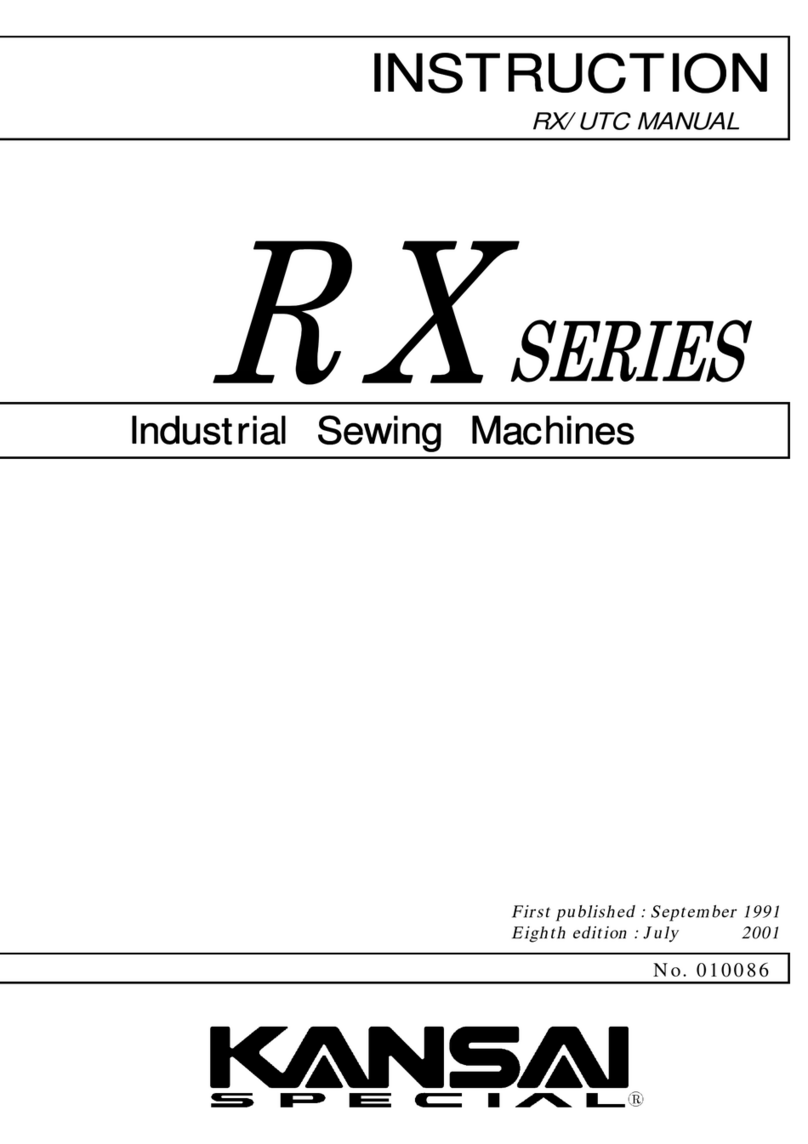
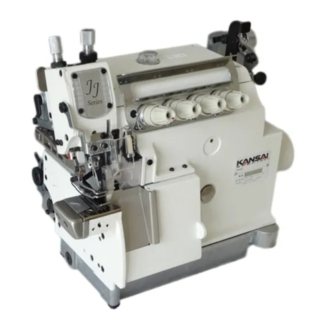
  9. KANSAI SPECIAL RX series User manual

KANSAI SPECIAL RX series User manual

Incii.!>lrial
Sawing
Machines
"?i«n
•
RX
SERIES
MECHANICS
MANUAL
A'-'-m
/)
MORIMOTO
MFG.
CO.,
LTD.
From the library of: Superior Sewing Machine & Supply LLC
V>'i^4Av&aJl>u
'15,
'-•'5
Table
of
Contents
ii£-:-SVi:A.V','•
-.-J.-';?-.iv
tisT^jit'e
Pip
• .
:••
-i.^'
From the library of: Superior Sewing Machine & Supply LLC
"I.^^iooper Angle
(Refer
to
Rg
1&
2)
Fig 1:
The
correct
angle is 2'30'as
demonstrated
in
Figl.
The
tip of the looper should be
1mm to 1.2mm forward of the front edge
of the looper
at
apoint measuring 25mm
to
the
right
of
the
tip.
Fig 2: In
order
to
adjust
this
angle refer to
Fig
2.
Loosen
screw
(A) to
adjust
looper
angle.
Note:
The
standard
position is
automatically
set
as
long
as
screw (A) is tightened
squarely
onto
the
flat
on
the
looper
shaft.
(3^
ooper
Timing
(Refer
to Rg 3-5)
Fig
3:
As
the
looper
moves
to
the
left,
behind
the
needles:
As
the
tip
of
the
looper
reaches
the
center
of
the
left
needle,
The
dimension
from
the
tip
of
the
looper
to
the
top
of
the
eye
of
the
needle
should
be
1
to
1.2mm.
Fig 1
25mm
Fig 2
Fig 3
From the library of: Superior Sewing Machine & Supply LLC
Fig
4: As
the
looper returns to the right, in front
of
the
needles:
As
the
tip
of
the
looper
reaches
the
center
of
the
left
needle,
the
dimension
from
the
tip
of
the
looper
to
the
top of the eye of the needle should be
0.2mm.
Fig
5: To adjust the timing,
loosen
screws
(A)
and
shift
the
position
of
the
upper
belt
gear
by holding the gear in place
and
turning
the
handvvheel(+) to
advance
or
(—)
to
retard
the
looper.
(^^^^^ooper-Needle
Distance
(Refer
to
Fig
e&
7)
Fig
6: When the looper isat its far right position,
the tip of the looper should be approxi
mately 6.5mm from the center of the
needle
bar.
This
dimension
is
standard
for
all
gauge
sizes.
\2
Fig 4
Fig 5
Fig
6
6.5mm
From the library of: Superior Sewing Machine & Supply LLC
Fig
7:
Because
it
is
common
practice
to
measure
looper-
needle
distance
from
the
tip
of
the
looper
to
the
center
of
the
right
needle
corresponding
looper-needle
distances
for
various
gauge
size
are
in
table
1.
To
adjust,
loosen
screw
(1)
and
move
looper
holder
(2)
right
or
left.
Table
1
Gauge
size
1/8"
3.2mm
4.9mm
5/23"
4.0mm
4.5mm
3/16"
4.8mm
4.1mm
7/32"
5.6mm
3.7mm
1/4"
6.4mm
3.3mm
4yNeedle Height
(Refer
to
Fig
8)
When
the
needle
bar
is
in
its
highest
position,
the
mark
P
on
the
handwheel
should
meet
the
mark
A
(Refer
to
Fig
8)
As
the
looper
moves
to
the
left,
behind
the
needles,
the
tip
of
the
looper
reaches
the
center
of
the
left
needle.
At
this
time,
the
distance
from
the
tip
of
the
looper
to
the
top
of
the
eye of
the
left needle
must
be
0.8
to
1.2mm.
To
adjust
the
height
and
alignment,
loosen
screw
(A);
set
correct
position;
and
tighten screw (A).
Make
sure
that
the
needles
are
aligned
in
the
center
of
the
needle
plate
holes.
Fig 7
(a)
Fig 8
From the library of: Superior Sewing Machine & Supply LLC
ooper-Needle
Clearance
(Refer
to
Fig
s)
When
the
tip
of
looper
(A)
meets
the
left
needle
(C)
the
clearance
between
them
should
be
0.2mm
to
0.3mm.
This
adjustment
can
be
made
by
loosening
screw(D)on
the
looper
holder,
moving
the
looper
frontwards
or
backwards
to
the
appropriate
setting,
and
retightening
screw
(D).
Note:
As
the
looper
moves
to
the
left,
behind
the
needles,
the
tip
of
the
looper (A) will
contact
the
right
needle slightly (0~
0.05mm).
(^^^I^Looper
Avoid
Angle
(Refer
to
Fig
10-13)
Fig 10
0.2-
i
0.3mmr9
°
0.2-
0.3mm"T?
Fig 12
Fig
9
3
Needle
2
Needle
Fig 13
Fig 10:
Shows
the
correct
looper
motion
Fig
11: Shows avoid eccentric
(A),
adjustment
screw
(B),
advanced
timing
mark
(C),
retarded
timing
mark
(D)
and
standard
timing
mark
(E).
Fig12: Shows exact location of the avoid eccentric in relation to the machine.
Fig
13:
A -
Standard
Angle
Path
B -
Advanced
Angle
Path
C -
Retarded
Angle
Path
From the library of: Superior Sewing Machine & Supply LLC
getting
The
Looper
Avoid
(Refer
to
Fig
14-15)
^
Note:
The
looper
avoiding
motion
requires
adjustment
when
a
different
diameter
needle
is
to
be
used. c
Fig
14
Fig
14:
When the
looper
moves
from
its
left-most
position, deflection of the
needle
should
beginwhen the tip of the left-most
needle
is 3.0mm-3.5mm from the looper eye.
The
contact
is from 0.3mm—0.6mm on the
back
of
the
looper.
Fig
15:
Align
dot
(D)
with
mark
(C)
for
standard
needles. In the case of extremely fine
needles loosen screw (A) and nut (B) and
move the dot (D) towards the rear of the
machine. In the case of extremely thick
needles move dot (D) towards the front of
the
machine.
Cl
-»-+•
-v^
j L
3~3.5mm
0.3-~0.6irm
Fig 15
From the library of: Superior Sewing Machine & Supply LLC
'f;®Rear
Needle Guard
(Refer
to
Fig
i6~i9)
Fig
16;
Height
Adjustment
With
needles
in
the
down
position
set
line
(A)
of
needle
guard
even
with
the
center
of
the
needle
eyes.
Fig
17A:
Clearance
(Right
Needle)
The
rear
needle
guard
contacts
the
right
needle
slightly
(0.0-0.5mm)
so
the
looper
will
not
contact
the
needle
as
it
moves
from
right
to
left.
Fig
17B:
Clearance
(Left Needle)
The
clearance
adjustment
between
the
left
needle
and
the
rear
needle
guard
is
0.05~0.1mm.
Fig
18:
To
Adjust
Loosen
screw
(C) to
adjust
front-back
position.
Loosen
screw
(B) to
set
height
and
angle.
fig
19:
Standard
setting
Align
the
mark
on
eccentric
(D) with
the
mark
on
the
main
shaft
for
standard
needle
guard
timing.
Fig 17A
Right Needle
Contact
0
to
0.05mm
Fig 18
Fig 19
inc
Fig 16
Fig 17B
Left
Needle
Clearance
0.05
to
0.1mm
— c
From the library of: Superior Sewing Machine & Supply LLC
ront
Needle
Guard
(Refer
to
Fig
20^-22)
Fig20: Front Needle Guard Height
Set
the
contact
edge of the front needle
guard
1.8 to 2.3mm above the tip of
the
left needle when the tip of the looper is
behind
the
center
of
the
left
needle.
Fig
21:
Front
Needle
Guard
Clearance
The
clearance
between
the
needles
and
the
front
needle
guard
should
be
the
follo
wing:
A)
0.00.05mm
for
the
left
needle
B) 0.1
~0.2mm
for
the
right
needle
Fig
22:
Adjustments
A)
To
adjust
the
height
and
angle
loosen
screw
(A)
B)
To
adjust
the
front-back position
loosen
screw
(B)
0.0~0.2mm
From the library of: Superior Sewing Machine & Supply LLC
|lwTop
Cover Spreader
(Refer
to
Fig
23-27)
Fig 23:
Screw
(A) allows for
adjustment
of the left
most
position.
Screw
(B) is for
height
adjustment
of
the
top
cover
spreader
and
clearance
between
the
spreader
and
the
needles.
Fig
24:
The
proper
distance between the
top
spreader
and
the
needle plate is
8.5-
9.5mm.
(Refer
to
table
2
for
recommended
distance
according
to
gauge
size.)
Table
2
Gauge
Spreader
Height
1/8"
3.2mm
9.5mm
5/23"
4.0mm
9.5mm
3/16"
4.8mm
9.5mm
7/32"
5.6mm
8.5mm
1/4"
6.4mm
8.5mm
Fig 25A:Set
the
tip of the thread hook 4.5 to 5.5mm
to
the
left
of
the
center
of
the
left
needle.
Fig 25B:Set the tip of the thread hook
(C)
0.5 to
0.8mm
from
the
front
of
the
left
needle.
Fig
26:
To
adjust spreader stroke loosen nut (D)
and
raise
or
lower
the
connecting
pin
(E).
Fig
27:
To
shorten
spreader
stroke for narrow
gauge
sizes move the connecting pin
towards
(a).
To
increase
spreader
stroke
for wide
gauge
sizes
and
long stitch
lengths
move
the
connecting pin
towards
(b).
8.5~9.5mm
Fig
25
A
4.5~5.5mm
rt..
Fig
26
Fig
27
0.5-
0.8mm
Fig
23
Fig
24
Fig
25
B
I:y.
From the library of: Superior Sewing Machine & Supply LLC
op
Cover
Thread
Guide
(Refer
to
Rg
28-'30)
Fig
28: Proper setting of the top cover thread
guide(D) is0.5-0.8mm above the spreader.
The
proper
setting of eyelet (B) is 1.0mm
above
thread
guide
(D).
Fig
29: At the time the top cover looper is in its
right-most position, the tip of the thread
hook
should
be
visible
in
the
center
of
the
slot
of
the
thread
guide
(D).
Fig
30:
Align the top cover thread eyelet (F)
directly in front of top cover thread guide
(D)
slot.
To do this, Loosen screw (G).
fl^Top
Cover
Timing
(Refer
to
Rg
31
&
32)
Fig
31:
This diagram shows the proper alignment
of the top cover spreadereccentric (B)and
top shaft. For proper alignment it is
recommended
that
timing mark (D) is
aligned with mark (C) on top shaft.
Fig
32: To adjust the top cover timing, loosen
screws (A) in Fig 31and turn the eccentric
towards
(E) to
advance
the
timing
or
towards
(F)
to
retard
the
timing.
Note:
The
standard
setting allows the needle
bar
to drop slightly before the spreader
returns
to
the
right.
Fig
28
Fig
29
Fig
30
Fig
31
Fig
32
i
0 0
0.5iTtrD
o
o
o
\ B
From the library of: Superior Sewing Machine & Supply LLC
Feed
Dog
Alignment
(Refer
to
Fig
33 &
34)
Fig
33:
Position
for
main
feed
bar
(B)
left-right
is
controlled
by
feed
rocker
guides
held
in
place
by
screws
(C & D), feed
bar
guide
plate
held
by
screws
(J)
and
feed
lifting
shaft
(G)
held
with
collars
(E)
and
feed
lever
screws
(F).
Front-back
position
of
differential
is
regulated
by
feed
shaft
(I)
held
by
screws
(F).
Fig
34:
To
center
the
front
feed
dog,
loosen
screw
(G)
and
adjust
eccentric
(F)
centering
the
feed
dog
for
equal
clearance
at
maximum
differential
feed
length.
Feed
Dog
Height
(Refer
to
Fig
35 &
36)
Fig
35:
At
their
highest
point,
both
the
main
and
differential
feed
dogs
should
be
no
more
than
one
tooth
height
(1.01.2mm)
above
the
needle
plate.
To
adjust
the
height
of
the
rear
feeder
loosen
screw
(A).
To
adjust
left-right
position
of differential feeder
loosen
screw
(C).
Fig
36:
It is
important
that
the
teeth
of
the
rear
feed
dog
and
those
of
the
front
feed
dog
are
at
the
same
height
above
the
needle
plate.
To
adjust
tilt
of
feeders
loosen
screws
(D) in feed lifting lever (C)
and
adjust
feed
lifting
shaft
(E) for
correct
tilt
angle.
Fig
33
Fig 35 1.0--1.2mm
Fig
36
10
From the library of: Superior Sewing Machine & Supply LLC
llvStitch
Length
(Refer
to
Fig
37-40)
Fig
37&38:
To
adjust
stitch
length,
press
main
stitch
regulator
button
(A)
and
turn
hand
wheel
until
button
(A)
drops
into
detent.
Then
turn
the
handwheel
in
the
desired
direction
to
increase/decrease
main
feed
stitch
length.
The
marks
on
the
hand-
wheel
(S, M, L) will align with pin(B).
Table
3
Stitch
Stitches
Stitches
Length
Per
inch
Per
30
MM
3.6mm
7.0
8.0
2.4mm
10.5
12.5
1.4mm
18.0
21.0
Fig
39:
Adjust
(C) to
obtain
desired
feed
ratio.
Loosen
the
handnut
(E,
Fig
40),
turn
(C) to
desired position,
and
retighten
handnut
(E).
Table4-Dlfferenlial
Feed
Ratio
Stitch
Maximum
Minimum
Length
Feed
Ratio
Feed
Ratio
3.6mm
1:1.1
1:0.3
2.5mm
1:1.6
1:0.4
2.0mm
1:2.0
1:0.5
1.4
mm
1:2.9
1:0.7
Fig 40: It is possible to
vary
the differential feed
intermittently.
To
do
this,
connect
a
chain,
fastened
to a
foot
pedal,
to
the
front of the lever. Next,
loosen
hand
nut
(E),
set
the
upper
limit
of
the
lever
with
the
adjusting
knob
(C).
set
the
lower
limit
of
the
lever
with
the
stopper
cam
(D).
When
working
the
differential
intermittently,
leave
handnut
(E)
loose.
11
Fig
37
Fig
39
Fig
40
From the library of: Superior Sewing Machine & Supply LLC
^^Presser
Foot
(Refer
to
Fig
41-43)
Fig 41:
To
ensure
proper
sewing
the
presser
foot
must
be
centered
above
the
needle
plate
so
the
needle
holes
line
up
correctly
with
the
needles.
To
adjust
loosen
screw
(A).
Fig
42:
The
proper
height
for
presser
foot lift is
6-7mm
above
the
needle
plate.
Fig
43:
To
set
presser
foot
lift
height
adjust
(B) to
stop
foot
lift
lever
at
desired
height
and
lock
nut
(C).
Note:
During
the
sewing
operation
use
only
enough
pressure
on
the
presser
foot
to
move
the
garment
smoothly.
Over
pressuring
the
presser
may
cause
damage
to
the
garment
and
the
machine.
(^)E^e\e\
Adjustments
(Refer
to
Fig
44-47)
Fig
44:
Silicone
Tank—The
eyelet
should
be
appro.ximately
15-^200101
above
the
center
of
screw
(A).
Fig
42
L
Fig
43
Fig
44
Silicone
Tank
1;?
From the library of: Superior Sewing Machine & Supply LLC
Fig
45:
Needle
Thread
Take
Up
The
distance
from
the
eyelets
to
the
first
screw
(B)
should
be
55mm.
To
adjust,
loosen
screws
(B)
and
(C)
and
move
the
eyelet left or right. Retighten(B)
and
(C).
At
the
time
the
needles
are
in
the
lowest
position,
the
take
up
should
be
horizontal. To adjust, loosen screw (D),
and
move
the
take
up
to
the
horizontal
position.
Retighten
(D).
Fig
46; Take Up Timing Adjustment-To adjust
take
up
timing
remove top cover to
gain
access
to
collar
and
driving
lever.
The
distance
between
collar
and
driving
lever
is
5.5mm.
Fig 47: Needle Bar Thread Take Up
Standard
Setting:
When
needle
bar
is as
its lowest point, the eyelet (A) should be
2mm
above
the
thread
takeup
(B).
To
decrease
loop size lower the takeup.
To
increase
loop size raise the takeup
or
place
thread
over
both
sides
of
thread
takeup
(B).
13
55mm
Fig
45
Fig
46
5.5mm
Fig
47
From the library of: Superior Sewing Machine & Supply LLC
^ISnhe
Timing
Belt
.
O.
Note:
There
are
3
sizes
of
belts
for
RX-9000
series
machines
(A, B, C).
During
the
life
of
the
machine
the
belt
may
stretch
and
the
machine
may
require
another
belt.
Belt
(A) is
the
largest
and
(B)
and
(C)
are
slightly
smaller
(1-2.5mm
difference)
(I^^Steps
To
Replace
The
Timing
Belt
(Refer
to
Fig
48-52)
Fig
48:
Remove
the
top
cover
and
the
oil
pan
from
the
machine.
(Drain
Oil
before
removing
pan)
Fig 49: Loosen
screws
(A)
and
remove the
upper
shaft.
Fig
48
Fig
49
14
From the library of: Superior Sewing Machine & Supply LLC
Fig
50:
Loosen
screw
(J)
remove
pulley
(I). Loosen
screw
(H)
and
remove
fan (G). Remove
screws
(F)
and
remove
flange (E). Loosen screws (C)
and
remove
bearing
(D).
Fig
50
Fig 51:
Remove
the
belt
as
shown.
Fig
52:
Place
the
now
timing
belt
on
the
timing
pulley
on
the
lower
shaft.
Replace
following
parts:
a.
Replace
the
bearing,
"D"
I).
Replace
the
flange.
"I*'"
c.
Replace
the
fan,
"Ci"
d.
Replace
the
pulley,
"I"
Note:
Wlien
the
bearing
is
replaced
on
the
lower
sliafl,
he
sure
the
top
screw
is
set
securely
into
the
si)ot
on
the
siiaft.
Replace
tiie
upper
shaft
set
into
the
machine
by
passing
the
shaft
through
the
timing
belt
and
inserting
the
end
of
the
shaft
into
the
top
shaft
union.
Turn
the
pulley
until
the
looper
is in
its
rightmost
position.
Move
the
needle
bar
by
hand
until
it is in
its
lowest
position.
Turn
the
handwheel,
being
sure
that
neither
the
looper
nor
the
needle
bar
move
from
their
e.xtreme
positions,
until
the
"P"
mark
on
the
handwheel
is
in-line
with
the
brass
stud
("0")
on
the
machine.
Retighten
tlie
set
screws
("A",
Fig
49)
on
the
top
shaft
union.
15
From the library of: Superior Sewing Machine & Supply LLC

Other KANSAI SPECIAL Sewing Machine manuals
KANSAI SPECIAL DFB Series User manual

KANSAI SPECIAL

KANSAI SPECIAL DFB Series User manual

KANSAI SPECIAL HDX Series User manual

KANSAI SPECIAL

KANSAI SPECIAL HDX Series User manual

KANSAI SPECIAL JJ Series User manual

KANSAI SPECIAL

KANSAI SPECIAL JJ Series User manual

KANSAI SPECIAL SX Series User manual

KANSAI SPECIAL

KANSAI SPECIAL SX Series User manual

KANSAI SPECIAL NC Series User manual

KANSAI SPECIAL

KANSAI SPECIAL NC Series User manual

KANSAI SPECIAL BLX2202PC User manual

KANSAI SPECIAL

KANSAI SPECIAL BLX2202PC User manual

KANSAI SPECIAL DFB1412PS User manual

KANSAI SPECIAL

KANSAI SPECIAL DFB1412PS User manual

KANSAI SPECIAL PX302-4W User manual

KANSAI SPECIAL

KANSAI SPECIAL PX302-4W User manual

KANSAI SPECIAL SX Series User manual

KANSAI SPECIAL

KANSAI SPECIAL SX Series User manual

KANSAI SPECIAL DVK1702B User manual

KANSAI SPECIAL

KANSAI SPECIAL DVK1702B User manual
KANSAI SPECIAL LX-SP Series User manual

KANSAI SPECIAL

KANSAI SPECIAL LX-SP Series User manual

KANSAI SPECIAL UF Series User manual

KANSAI SPECIAL

KANSAI SPECIAL UF Series User manual

KANSAI SPECIAL DFB MR-S Series User manual

KANSAI SPECIAL

KANSAI SPECIAL DFB MR-S Series User manual

KANSAI SPECIAL DLR Series User manual

KANSAI SPECIAL

KANSAI SPECIAL DLR Series User manual

KANSAI SPECIAL DX9902-3U User manual

KANSAI SPECIAL

KANSAI SPECIAL DX9902-3U User manual

KANSAI SPECIAL V 7100 Series User manual

KANSAI SPECIAL

KANSAI SPECIAL V 7100 Series User manual

KANSAI SPECIAL W-8042 User manual

KANSAI SPECIAL

KANSAI SPECIAL W-8042 User manual

KANSAI SPECIAL DVC-200 SERIES User manual

KANSAI SPECIAL

KANSAI SPECIAL DVC-200 SERIES User manual

KANSAI SPECIAL RX9701J Series User manual
KANSAI SPECIAL

KANSAI SPECIAL RX9701J Series User manual

KANSAI SPECIAL DPW-1300 Series User manual

KANSAI SPECIAL

KANSAI SPECIAL DPW-1300 Series User manual

KANSAI SPECIAL MZ Series User manual

KANSAI SPECIAL

KANSAI SPECIAL MZ Series User manual
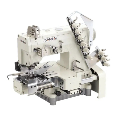
KANSAI SPECIAL BK-20 User manual

KANSAI SPECIAL

KANSAI SPECIAL BK-20 User manual

KANSAI SPECIAL DWK-1803D User manual

KANSAI SPECIAL

KANSAI SPECIAL DWK-1803D User manual

KANSAI SPECIAL DLR-1501SPF User manual

KANSAI SPECIAL

KANSAI SPECIAL DLR-1501SPF User manual

Popular Sewing Machine manuals by other brands

Pfaff 76 Instruction book

Pfaff

Pfaff 76 Instruction book

Duerkopp Adler 524-105 Spare parts

Duerkopp Adler

Duerkopp Adler 524-105 Spare parts

Janome MC 11000 - Service manual

Janome

Janome MC 11000 - Service manual

W6 WERTARBEIT N 656D Free Arm manual

W6

W6 WERTARBEIT N 656D Free Arm manual

Singer 114W121 Instructions for using

Singer

Singer 114W121 Instructions for using

Brother PE-700II instruction manual

Brother

Brother PE-700II instruction manual

Singer 185 Instructions for using

Singer

Singer 185 Instructions for using

Singer 1802 instructions

Singer

Singer 1802 instructions

APQS Lenni installation manual

APQS

APQS Lenni installation manual

Riccar 749L Instruction booklet

Riccar

Riccar 749L Instruction booklet

Singer 111W112 Instructions for using and adjusting

Singer

Singer 111W112 Instructions for using and adjusting

Butterfly B1501B/T Operation and service manual

Butterfly

Butterfly B1501B/T Operation and service manual

Brother BAS-342G PS instruction manual

Brother

Brother BAS-342G PS instruction manual

Singer SPARTAN 192 manual

Singer

Singer SPARTAN 192 manual

Brother Innov-is 2500D Manuel d'instructions

Brother

Brother Innov-is 2500D Manuel d'instructions

Garudan GP-510-143 User manual and  spare parts list

Garudan

Garudan GP-510-143 User manual and spare parts list

Merrylock MK 4055 Instruction book

Merrylock

Merrylock MK 4055 Instruction book

Brother ELS Lettering installation guide

Brother

Brother ELS Lettering installation guide

manuals.online logo
manuals.online logoBrands
  • About & Mission
  • Contact us
  • Privacy Policy
  • Terms and Conditions

Copyright 2025 Manuals.Online. All Rights Reserved.