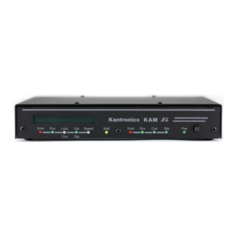
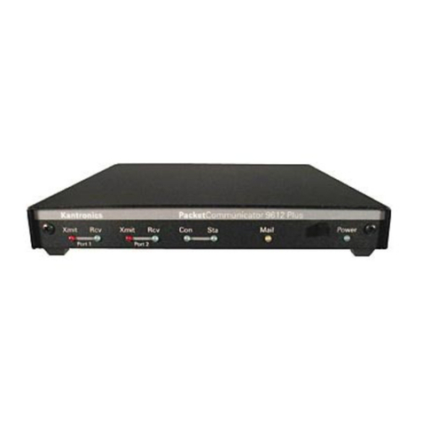
Kantronics KPC-9612 User manual

KPC-9612
Getting Started
and Reference Manual

KPC-9612 Version 5.2 July 19, 1994
2
Table of Contents
Who should read this manual .................................... 4
Before you start ......................................................... 4
About your KPC-9612
Front Panel ....................................................... 5
Rear Panel ........................................................ 6
Setting up your KPC-9612
Power Cable ...................................................... 6
KPC-9612 to Computer Cable ............................. 6
Initializing the KPC-9612 .................................... 7
Your First Connect ............................................. 7
KPC-9612 to 1200 baud Radio Cable ................... 8
Adjusting Receive Volume .................................. 8
Adjusting Transmit Drive Level ............................ 9
Wiring Diagrams ................................................ 10
KPC-9612 to 9600 baud Radio Cable ................... 13
Adjusting Transmit Drive level ............................ 13
Adjusting 9600 baud receive .............................. 13
Operating Packet ....................................................... 14
Connecting at 1200 baud ................................... 14
Connecting at 9600 baud ................................... 15
Introduction to Commands
Some Abbreviations ........................................... 16
Entry ................................................................ 16
Format ............................................................. 16
Parameter Types ............................................... 17
Commands ................................................................ 18
Operation of the KPC-9612 ........................................ 45
Packet Operation ............................................... 45
Kantronics PBBS ........................................................ 47
Setting Up Other Functions of your KPC-9612
PBBS ................................................................ 50
KA-Node ........................................................... 50
Gateway ........................................................... 50
PBBS SYSOP Functions ...................................... 50
Remote Access to your KPC-9612 ....................... 52
Host Mode Operation ......................................... 53
KISS Mode Operation ......................................... 54
Hardware Information
Precautions ....................................................... 55
Connecting to the Computer .............................. 55
Cable Wiring ..................................................... 55
Options ............................................................ 56
Software settings .............................................. 56
Connecting to your Radio
1200 Baud ........................................................ 57
9600 Baud ........................................................ 58
Transmit level adjustment
1200 Baud ........................................................ 59
9600 Baud ........................................................ 59
Watchdog Timer ................................................ 59
Microprocessor Watchdog Timer ......................... 59

KPC-9612 Version 5.2 July 19, 1994
3
Assembly and Disassembly of the KPC-9612 ........ 60
Hard Reset ....................................................... 60
Calibration/Equalization ...................................... 61
1200 baud adjustment ....................................... 61
9600 Baud Calibration ........................................ 61
KPC-9612 Jumpers .................................................... 63
Connector Configuration ............................................ 64
1200 baud radio port (DB-9) .............................. 64
Serial port (DB-25) ............................................ 65
Appllying power to the KPC-9612 ........................ 65
DTR/DSR/RTS/CTS connection ........................... 65
Specifications ............................................................. 66
ASCII Chart ............................................................... 67
Pacterm Manual ......................................................... 68
KPC-9612 Parts List ................................................... 71
KPC-9612 Parts Layout .............................................. 74
KPC-9612 Schematic .................................................. 75
KPC-9612 Manual Addenda ........................................... 76
KPC-9612 Version 6.0 Firmware with DAMA .............. 77
Additional commands in V6.0 ............................ 79

KPC-9612 Version 5.2 July 19, 1994
4
Who should read this manual?
The Getting Started portion of this manual is intended as a quick reference guide to assist new
users.
NOTE: The radio port wiring on the KPC-9612 is slightly different from other Kantronics TNCs as a
result of added control signal capabilities. All users should review this Information before connect-
ing the KPC-9612 to a radio.
Before You Start
Your KPC-9612 comes with one DB-9 (male) connector, one DB-15 (male) connector, 6 feet of 5-
conductor shielded cable, a 3.5 mm phone plug, and a 2.1 mm power connector. You must supply
the serial cable to connect the KPC-9612 to your Computer (DB-25 male required to connect to the
KPC-9612), a source of regulated de power (12 V nominal), and the connectors to interface with
your radio(s). Wring diagrams for some radios are included in this manual. If your radio is not
shown, use the guide-lines on pages 14 and 19, along with your radio manual, to determine prop-
er wiring.
To help you explore your KPC-9612, we've included a 3-½" disk with two terminal programs - Pac-
term and GMON. These programs are not copy protected and you are free to make copies on 5-
1/4" disks if necessary for your own personal use. The Pacterm program is no longer being updat-
ed; it is only provided as a simple program to get you started. The Pacterm documentation will be
found at the end of this manual. The GMON program is a slightly more sophisticated program, but
is not considered full-featured. Documentation for GMON is located on the disk in a file named
GMON.DOC.

KPC-9612 Version 5.2 July 19, 1994
5
About your KPC-9612
Front Panel
The front panel of the KPC-9612 has one switch and 8 LEDs. Seven of the LEDs are used to indi-
cate status and one is used as a power indicator. The status indicators are divided into three
groups. The left most LED is the power on indicator. Next to this is the power on switch. Following
the power switch is a group of two LEDs for Port 1 (1200 baud), a group of two LEDs for Port 2
(9600 baud) and finally a group of three LEDs for status. All LEDS may be turned off with the
LEDS command.
Controls/Indicators
Power This green LED lights to indicate that the KPC-9612 is turned on.
ON/OFF switch This push/push switch applies power to the KPC-9612. When depressed, the
KPC-9612 is turned on.
Port 1
Xmit This red LED lights when the KPC-9612 is transmitting on radio port 1 (1200 baud,
DB-9 connector).
Rcv This green LED lights when a signal is detected by the 1200 baud modem.
Port 2
Xmit This red LED lights when the KPC-9612 is transmitting on radio port 2 (9600 baud,
DB-15 connector).
Rcv This green LED lights when a signal is detected by the 9600 baud modem.
Status
Con This green LED lights to indicate that a connection exists on the currently selected
I/O stream.
Sta This green LED lights when your station has unacknowledged packets on the cur-
rent I/O stream.
Mail This yellow LED is lit when someone is connected to your PBBS (mailbox) and will
flash any time there is unread mail for your in the PBBS.

KPC-9612 Version 5.2 July 19, 1994
6
Rear Panel
Port 1 Port 2 Computer Power
The rear panel of the KPC-9612 has four connectors. The purpose of each connector is described
below:
Port 1 This DB-9 connector accepts the cable from your radio for 1200 baud packet opera-
tion.
Port 2 This DB-15 connector accepts the cabel from your radio for 9600 baud packet oper-
ation.
NOTE: Your radio MUST be capable of operating 9600 baud. Refer to your ra-
dio manual to determine the exact connections required.
Computer This DB-25 connector accepts the cable from your computer serial port. The KPC-
9612 communicates with RS-232 levels using standard ASCII characters for all com-
mands.
Power jack (2.1 mm) This connector is provided to apply external power (5.5 to 25 VDC) to
the KPC-9612. The center post is the positive connection and the sleeve is negative
(ground).
Setting up your KPC-9612
Power Cable
Using hookup wire, connect a 12 VDC power supply to the 2.1 mm plug (supplied) by connecting
the positive wire to the center of the plug and the negative wire to the sleeve. Insert the power
plug into the power jack at the rear of the KPC-9612.
KPC-9612 to Computer Cable
To connect your KPC-9612 to your Computer you will need to use a modem cable. The KPC-9612
requires a 25-pin male DB connector and your Computer will normally require either a 25-pin or a
9-pin female connector. As shipped from the factory, the KPC-9612 is configured so you may use a
25-wire cable. See the hardware section for details on reconfiguring the 25-pin serial connector on
the KPC-9612.
Connect your serial cable to the 25-pin connector on the rear of the KPC-9612, and the female
connector to your Computer serial port (COM port). We suggest you connect this cable to COM1 or
COM2 on your Computer. The Pacterm program used in conjunction with the examples in this man-
ual supports only these two COM ports.
For connection to other types of computers, refer to their software and hardware manuals. The
KPC-9612 will communicate with a terminal with a minimum of three wires connected (Txd, Rxd,
and SG). Your Software (terminal program) may require that other wires be connected. Refer to
the hardware section of this manual for a complete description of the connections in the KPC-
9612.

KPC-9612 Version 5.2 July 19, 1994
7
NOTE: There is no selection in the KPC-9612 for COM ports –the correct COM port depends only
on the physical connection you have made to your Computer serial port.
Initializing the KPC-9612
Now that the KPC-9612 is cabled to your Computer, the next step is to initialize it. Boot your Com-
puter as you normally do. Place the PACTERM disk (shipped with your KPC-9612) in the A (or B)
drive on your Computer and type A:PACTERM (or B:PACTERM) and press return, When the pro-
gram starts you will see a menu. If you are using COM2, press F7 to select COM2. Press the back-
space key on your Computer and you will be placed in the ONLINE mode of the Pacterm program.
Once the program is operating, turn on the KPC-9612 by depressing the ON/OFF switch on the
front panel and observe that the power LED lights. At this point the KPC-9612 will begin sending
you a message. Since Pacterm is set to communicate at 1200 baud, you may some garbage char-
acters followed by the message:
PRESS (*) TO SET BAUD RATE
When you see this message, press the * (asterisk) key on your keyboard. Do not type the () char-
acters, just the *. You rnust press the *within two (2) seconds of seeing the message printed. If
you performed this properly, the KPC-9612 will prompt you to ENTER YOUR CALLSIGN=>. If you
didn't press the *quickly enough, be patient and try again when you see the message.
Once you have pressed the *at the right time, the KPC-9612 prompts you to ENTER YOUR CALL-
SIGN=>. Type your amateur radio callsign and press return. The KPC-9612 then sends its sign-on
message:
KANTRONICS KPC9612 VERSION x.x
(C) COPYRIGHT 1994 BY KANTRONICS INC. ALL RIGHTS RESERVED
DUPLICATION PROHIBITED WITHOUT PERMISSION OF KANTRONICS.
cmd:
At this point your KPC-9612 is set to the NEWUSER Mode with only a limited command set. To ac-
cess all KPC-9612 commands you may want to give the command INTFACE TERMINAL.
Your First Connect
Now that you have initialized your KPC-9612, you are ready to try your first connect. Since you
have not connected the radio to the TNC yet, you'll simply connect to your personal mailbox in the
KPC-9612. This will help you to become comfortable with your KPC-9612 operation before connect-
ing your radios. At the cmd: prompt, type CONNECT call-1 (replace "call" with your amateur
callsign) and press return. Your KPC-9612 will then connect you to the mailbox. Your screen should
look something like this:
cmd:CONNECT N0GZZ-1
cmd:*** CONNECTED to N0GZZ-1
[KPC9612-5.2-HM$]
5000 BYTES AVAILABLE
THERE ARE NO MESSAGES
ENTER COMMAND B,J,K,L,R,S, or Help>
Now you can enter any of the mailbox commands shown (B,J,K,L,R,S or Help). Later you
will want to read the PBBS section of this manual for more Information. If you type the HELP com-

KPC-9612 Version 5.2 July 19, 1994
8
mand and press return, you'll see the KPC-9612 mailbox help file and then the standard mailbox
prompt:
ENTER COMMAND B,J,K,L,R,S, or Help>
Now disconnect (just like you will disconnect from any other station). First, return to Command
Mode by typing CONTROL-C on your keyboard. To do this, hold down the control key (usually
marked CTRL) and type the letter C. Release the control key. You should now see the cmd:
prompt, Next you must type the DISCONNE command and press return. You will receive the mas-
sage ***'DISCONNECTED and a new command prompt.
Congratulations! You have now completed your first connect.
KPC-9612 to 1200 baud Radio Cable
The next step in installing your KPC-9612 is to make the cable for the 1200 baud port (port 1) of
your KPC-9612 to your radio. To transmit and receive data, you must make the following pin con-
nections from the DB-9 connector to appropriate pins on your radio.
Pin1 (TXA) Transmit audio –This pin connects the microphone input of your radio. TXA is the
data being sent by your TNC.
Pin 3 (PTT) Push-to-Talk –This pin connects to the PTT pin of your radio. The PTT signal causes
the radio to transmit when the TNC has data to send. This pin on your radio may have a
different name (e.g. STBY), but the function as described in your radio manual should indi-
cate that a ground on this pin will cause the radio to transmit.
Pin 5 (RXA) Receive audio -This pin normally connects to the external speaker jack on your radio.
The supplied 3.5 mm phone plug can be used by connecting the tip to pin 5 and the sleeve
to pin 6. In some radios, receive audio is also available through the microphone connector.
If your radio provides this feature, you will probably need to set the CD command to SOFT-
WARE since this audio is usually unaffected by the squelch or volume controls of your ra-
dio.
Pin 6 Ground -This pin connects to the ground pin of your radio. If your radio has a separate mic
ground and PTT ground, we recommend that you connect the PTT ground and do not con-
nect the mic ground.
The DB-9 connector supplied with your KPC-9612 is a male connector. When
you look at the connector from the back (the point you will solder the wires)
the pins are numbered as shown in the diagram.
After you have completed this cable, connect it to your KPC-9612 and secure
the DB-9 connector with the scres. Connect the other end to your radio.
DB-9 Male
wiring side
Adjusting Receive Volume
To adjust the receiving volume on your 1200 baud radio properly, first turn on your computer, start
you terminal program and turn on the KPC-9612. Be sure the CD command in the KPC-9612 is set
to INTERNAL. Next turn on your radio and open the squelch control (fully counter-clockwise).
Slowly turn the volume up until the RCV LED on the KPC-9612 lights. Increase the volume control
slightly from this point. Next, turn the squelch control clockwise until the RCV LED goes out or until
the noise in your speaker stops. Your radio is now properly adjusted for receive volume.

KPC-9612 Version 5.2 July 19, 1994
9
NOTE: If your RCV LED does not go out when you turn the squelch control clockwise, you will
need to set the CD command to SOFTWARE. This may occur when receive audio is taken from the
microphone connector or from a dedicated data jack.
Adjusting Transmit Drive Level
The drive level from the KPC-9612 to your radio can be ad-
justed by using potentiometer R22 and jumper J5. When J5
is placed on both posts, the drive may be adjusted through
the high range (140 mV to 4 Vp-p) with R22. Placing J5 on
one post only selects the low range (2 mV to 60 mVp-p).
This jumper is set at the factory for the low range, which
provides the proper drive level to most radios. If your radio
requires a higher drive, move J5 and adjust R22. See the di-
agram at right for the location of these components. You
should adjust the drive level to provide about 3 to 3.5 kHz
deviation with your radio. If you don't have access to a de-
viation meter, adjust this so your packet transmissions
sound about the same volume as most of the others you
hear.
Back of KPC-9612

KPC-9612 Version 5.2 July 19, 1994
10

KPC-9612 Version 5.2 July 19, 1994
11

KPC-9612 Version 5.2 July 19, 1994
12

KPC-9612 Version 5.2 July 19, 1994
13
KPC-9612 to 9600 baud Radio Cable
The final step in connecting your KPC-9612 is to make the cable from the KPC-9612 to your 9600
baud radio.
NOTE that 9600 baud operation requires a radio that is specifically designed or modi-
fied for 9600 baud operation. Not all radios are capable of being modified for 9600 baud
.
Connections to a radio for 9600 baud operation are made through the
DB-15 connector on the rear panel. In order to transmit and receive
9600 baud packet, you must connect the following pins to your radio:
DB-15 Male
wiring side
Pin 1 (PTT) Push-to-Talk –This pin connects to the PTT pin of your radio. The PTT signal causes
the radio to transmit when the TNC has data to send. This pin on your radio may have a
different name (e.g. STBY), but the function as described in your radio manual should indi-
cate that a ground on this pin will cause the radio to transmit.
Pin 2 (RXA) Receive Data –This pin connects to the 9600 baud data output pin of your radio.
Pin 3 (TXA) Transmit Data –This pin connects to the modulator stage of the radio. Those radios
that are "9600-ready" will identify this pin as the 9600 baud input from your TNC.
Pin 11Ground –This pin connects to the ground of your radio. (
NOTE: Pin 9 and 10 are also
ground on the KPC-9612.
)
Adjusting Transmit Drive Level
The drive level of the 9600 baud modem in the KPC-9612 is adjusted using R32 and jumper J7.
When J7 is placed on both posts, R32 will adjust the drive through the high range (80 mV to 4 Vp-
p), This will be the normal setting for most radios. If you're using a Kantronics D4-10 or DVR2-2
radio, J7 will need to be placed on one post only, selecting the low range (2 mV to 100 mVp-p).
Typically, the proper deviation for 9600 baud operation is about 3 kHz. If you don't have a devia-
tion meter, you may have a difficult time in adjusting the level properly. However, start by setting
the drive level as recommended for your brand of radio (see your radio manual). You may then
have to adjust the drive control (R32) until you achieve acceptable performance.
If you have an existing 9600 baud node or other
station operating in your area, we suggest you
attempt to digipeat through that station (see the
UNPROTO command) while making this adjust-
ment.
Adjusting 9600 baud Receive
As shipped from the factory, the KPC-9612 is set
for proper reception with many of the 9600-baud
ready radios on the market. (J8 is on the center
post and post 1.) Should you find that your KPC-
9612 is not receiving well, or if you want to fine-
tune your KPC-9612 for your specific radio, you
will need to place the jumper J8 on the center
post and the post marked 2. This enables R33 for
variable equalization. (See the diagramm at the
right for component location.)
Front of KPC-9612

KPC-9612 Version 5.2 July 19, 1994
14
Adjusting the KPC-9612 for receive is fairly easy. Connect a voltmeter (analog preferred) to pin 8
of the DB-15 connector (RX S/N) or test point J on the PC board and pin 10 (ground) of the DB-
15. Have another 9600 baud station transmit long packet bursts, and adjust R33 for a peak read-
ing on your Voltmeter. (Maximum reading is approximately 3 VDC.) This is the signal quality line in-
dicating how well the 9600 baud modem is decoding the received signal. This indication is more
accurate than using the eye-pattern method (used with the G3RUH modems). (See the Calibra-
tion/Equalization section later in this manual for more information.)
Operating Packet
After you have connected the KPC-9612 to the radio(s), you will begin receiving packets. As pack-
ets are received, the KPC-9612 sends them to your terminal for display. A typical received packet
might look like this:
W0XI>WK5M/1<<I00>>:
Good morning.
The first line is the header line which displays the callsigns of the stations talking. The /1 indicates
that this packet was received on the 1200 baud port. A packet received on the 9600 baud port
would show /2 at the end of the header line. The following line(s} are the actual transmitted mes-
sage. You may see the RCV LED light at times, indicating that a signal is being received, although
nothing displays on your screen. This is normal and is the result of the many monitoring com-
mands that are discussed in detail in the Reference Manual.
As you monitor, you will begin to learn which stations are in your area and will then want to try to
connect to one of them. To instruct your KPC-9612 to connect, disconnect or to change any of the
operating pararneters, you must be in the COMMAND Mode. To send data from your keyboard over
the radio, you will need to be in the CONVERS Mode. The KPC-9612 automatically switches to the
CONVERS Mode when you connect to someone and returns to the COMMAND Mode when a dis-
connect occurs. If you are in the CONVERS Mode and want to force your KPC-9612 back to the
COMMAND Mode, type CONTROL-C. Remember, you must be in the COMMAND Mode in order to
give instructions to your KPC-9612.
Connecting at 1200 baud
Suppose you want to connect to WD0EMR, a station you monitored on port 1 (1200 baud). First,
be sure you have the KPC-9612 in the Command Mode. To do this, type a CONTROL-C and press
return. You should see a command prompt (cmd:). Since this station was monitored on 1200
baud, you must make sure your KPC-9612 is ready to transmit packet at 1200 baud. Type the ver-
tical bar (|) and the letter "a". This will set the KPC-9612 to transmit on port 1. Now use the CON-
NECT command to start the connection. To connect to WD0EMR, simply type CONNECT WD0EMR
and press return, just as you did in the sample connect to your mailbox.
In some cases you may need to use a relay station, called a digipeater, to contact another station.
This is similar to using a voice repeater when the station you want to talk to is out of simplex
range. To connect to a station using digipeaters, you still use the CONNECT command, but you
must also specify the callsigns (or aliases) of the digipeaters that must be used. For instance, if
you need to use two digipeaters with callsigns of W0XI and KO0W in order to connect to KA5ZTX,
you enter the command as:
CONNECT KA5ZTX VIA W0XI,KO0W

KPC-9612 Version 5.2 July 19, 1994
15
Once the connection has been made, you'll receive a message back on your screen from the KPC-
9612 that says ***CONNECTED to WD0EMR (or ***CONNECTED to KA5ZTX via
W0XI.K00W). At that point, you are ready to start talking to the other station since the KPC-9612
automatically switched to the CONVERS Mode.
After you have completed your conversation, simply press CONTROL-C to return your KPC-9612 to
the Command Mode (cmd: appears) and then instruct your KPC-9612 to disconnect. From the
cmd: prompt, type D and press return.
Connecting at 9600 baud
If the Station you want to connect to is operating 9600 baud (indicated by the /2 in the monitored
data) you must first switch your KPC-9612 to transmit at 9600 baud. To do this, type the tilde
character (~) and then the letter "a" This sets the KPC-9612 to transmit packet on the A stream of
the 9600 baud port. Once this is done you would then connect just as you did above, using the
CONNECT command. When you are through with your conversation, you disconnect as you did in
the previous examples.
Note that the vertical bar (|) and the tilde (~) are the streamswitch characters defined in the KPC-
9612, with the vertical bar indicating 1200 baud and the tilde indicating 9600 baud. You switch
back and forth between the two by simply typing the streamswitch character followed by the fetter
of the stream you want to use. The KPC-9612 defaults to ten (10) streams for 1200 baud and ten
for 9600 baud, identified by the letters A-J.

KPC-9612 Version 5.2 July 19, 1994
16
Introduction to Commands
Some Abbreviations
<Ctrl-x>: This represents a single control character sent from your terminal program to the
KPC-9612. To send this character, press and hold the control key and type the sec-
ond key (x) while holding the control key down. If another letter follows this (i.e.
<Ctrl-C>T) do not continue to hold the control key down while pressing the other
letter. If your keyboard does not have a control key, consult your computer/terminal
manual to determine which key performs the control key function. If your terminal
does not have a key that performs this function, you will need to change the param-
eters in the KPC-9612 that define these special Ctrl key characters.
$ preceding a number denotes a hex number {base 16)
<CR>: carriage return, $OD, decimal 13, <Ctrl-M>, ENTER key
<LF>: line feed, $OA, decimal 10, <Ctrl-J> I/O: In put/Output
Entry
A command is entered to the KPC-9612 by typing the command name and its argument (setting or
value) in the Command Mode. The prompt for the Command Mode is cmd:
The command name and the argument must be separated by a space, and the KPC-9612 takes ac-
tion when a carriage return <CR> is typed. All commands may be abbreviated to the shortest
string indicated by the CAPITAL letters in the command reference
You may examine the value of any parameter by typing the command name followed by a <CR>.
The DISPLAY command allows you to display sets of related parameters as a group.
Format
All commands are listed alphabetically in this manual. A precedes a command from the NEWUS-
ER set (when a unit is new, INTFACE is set to NEWUSER, or a hard reset has been performed). All
other commands begin with a . On the first line of a command will be the command name fol-
lowed by any arguments used with the command. Arguments shown in square brackets ([ ]) are
optional. If a command accepts several different values, or a range of values, the permissible val-
ues will be shown in parentheses ( ). Arguments may also be shown separated by a vertical bar
(|). This indicates that you may choose ONE of the items separated by the bar. The factory default
value for the parameter or command is shown in curly braces ({ }).
Some of the commands in the KPC-9612 are dual-port commands, allowing you to set one value
for the 1200 baud port of the KPC-9612, and a different value for the 9600 baud port. This is indi-
cated by a dual-port default value (e.g. {192/63}). The value shown before the slash bar is the
value used for the 1200 baud port of the KPC-9612, and the value after the slash is used for the
9600 baud port.

KPC-9612 Version 5.2 July 19, 1994
17
Parameter Types
n
(range): Any number within the range is permissible.
n
($00 - $FF): Any HEX number –normally used to define an ASCII character. When entering a
HEX number, be sure to type the $ symbol to indicate a hex number follows. See
the ASCII chart at the end of the manual to determine the code required.
flags (choiceA|choiceB): Many commands allow a choice of two or more possible entries (e.g. ON l
OFF). For ON/OFF choices, you may also enter YES or NO. Other commands accept
one of several choices (ON l OFF l TO l FROM). Enter the appropriate word to indi-
cate your choice.
callsigns xxxxxx-n: Many commands require a callsign or alias as an argument. These parameters
are normally set to Amateur callsigns, however any combination of 6 numbers
and/or letters is permitted. You may optionally include an "extension" (SSID, Secon-
dary Station Identifier) which is a decimal number between 0 and 15 (inclusive)
used to distinguish two or more stations on the air with the same amateur call.
SSIDs of 0 are not displayed by the KPC-9612.

KPC-9612 Version 5.2 July 19, 1994
18
Commands
8bitconv ON|OFF {OFF}
When ON, transmission of 8-bit data is allowed. When OFF, the 8th data bit is set to 0 before trans-
mission and all data received will have the 8th bit set to 0.
AUtolf ON|OFF {ON}
When ON, a line feed is sent to the terminal after each carriage return. This parameter should be
set ON when overprinting occurs and the terminal being used does not automatically supply its
own linefeed after a carriage return. This command only affects the data sent to the terminal, not
data sent to the radio.
See also: cr, lfadd
Ax25l2v2 ON l OFF {ON/ON}
This command provides compatibility with all known packet units implementing the AX.25 protocol.
When ON, Level 2 Version 2 protocol is implemented and the TNC will automatically adapt to
whichever version the connecting station is using. When OFF, Level 2 Version 1 is implemented.
Set this command to OFF if you need to digipeat through other units which do not digipeat version
2 packets. You may also find benefit from setting this command OFF when using several digipeat-
ers (not nodes) to send packets, or when conditions are marginal between the two stations in-
volved. (NOTE: Changing this setting after connecting to another Station will have no effect on the
current connection.)
The major difference in V1 and V2 protocol is the method used to handle retries. Version 1 will re-
send the entire packet and then disconnect if the RETRY count is reached. Version 2 will first send
a poll, the response to this poll will determine if the packet was received. It is possible that the ack
was collided with, and therefore the packet does not need to be resent. If the packet was not re-
ceived it will be retransmitted. Each time a poll is answered the TRIES count is reset to 0. If the
RETRY count is reached, Version 2 will attempt to reconnect unless RELINK is OFF. If the recon-
nect attempt is unsuccessful, then Version 2 will issue a disconnect.
See also: relink, retry, tries
For more Information, the book AX.25 Amateur Packet-Radio Link-Layer Protocol Version 2.0 Octo-
ber 1984. can be obtained from the ARRL.
AXDclay
n
(
n
= 0 –255) {0/0}
This command specifies a period of time to wait, in addition to TXDELAY, after keying the radio be-
fore data is transmitted. If you operate through a voice repeater, this delay may be required to al-
low the repeater's transmitter to turn on. Each unit represents 10 milliseconds.

KPC-9612 Version 5.2 July 19, 1994
19
AXHang n (
n
= 0 –255) {0/0}
When operating through a voice repeater this command should be set to the hang time of the re-
peater. If the TNG has detected activity within this time interval, it will not use the AXDELAY set-
ting since the repeater should still be transmitting. Each unit represents 10 milliseconds.
Beacon [Every | After]
n
(
n
= 0 –255) {EVERY 0/EVERY 0}
When set to EVERY, a beacon packet will be transmitted every
n
minutes. When set to AFTER, a
beacon packet will be transmitted ONCE after
n
minutes of no channel activity. Setting
n
to 0 will
disable beacon transmissions.
See also: btext, unproto
BKondel ON|OFF {ON}
When ON, the KPC-9612 will echo a back space-space-back space sequence to your terminal when
the DELETE character is received from the terminal. When OFF, the KPC-9612 echoes a backslash
(\) character when the DELETE character is received.
BP96 ON|OFF {OFF}
When OFF, the 9600 baud transmit waveform filter provides the best eye pattern on the transmit-
ted signal. The transmitted bandwidth is slightly wider than a G3RUH modem. When ON, the
transmitted bandwidth is slightly narrower than the G3RUH modem, and the transmitted eye pat-
tern is slightly distorted, but will work with most radios.
BText
text
(up to 128 characters) {blank}
Specifies the contents of a BEACON packet. To clear the BTEXT, enter a single % character (BTEXT
%).
See also: beacon
BUDCalls [+|-]callsign(s)|NONE {NONE}
A list of up to 10 callsigns for use with BUDLIST or CONLIST. To delete or add individual entries,
precede the callsign with a "-" or "+" respectively.
See also: budlist, conlist
BUdlist OFF|TO|FROM|ON {OFF/OFF}
When OFF, all packets are eligible to be displayed as monitored packets. When ON, only those
packets TO or FROM stations listed in the BUDCALLS will be monitored When TO, only those pack-
ets addressed TO stations in the BUDCALLS will be monitored, and when FROM, only those pack-
ets FROM stations listed in BUDCALLS will be monitored.
See also: budcalls, monitor, suplist

KPC-9612 Version 5.2 July 19, 1994
20
CALibrat {immediate command}
The CALIBRAT command is used to generate a signal which maybe used as an aid in tuning the
transceiver for operation. Use of this command is detailed in the Calibration/Equalization section of
this manual. The letter X will return you to the Command Mode and perform a soft reset.
CAnline
n
(
n
= $00 –$FF) {$18 <Ctrl-X>}
When entering commands or data to the KPC-9612, you may cancel the current line you are typing
(back to the last un-passed carriage return) by sending a <Ctrl-X> from your terminal.
See also: canpac, epactime, pass
CANPac
n
(
n
= $00 - $FF) {$19 <Ctrl-Y>}
When entering commands or data to the KPC-9612, you may cancel the entire packet (back to the
last un-passed SENDPAC character) by sending a <Ctrl-Y> from the terminal. When in Command
Mode, <CtrI-Y> acts as a cancel output character, turning off any output from the KPC-9612. Typ-
ing another <Ctrl-Y> re-enables output.
See also: canline, cpactime, sendpac
CD INTERNAL|EXTERNAL|SOFTWARE {INTERNAL/INTERNAL)
When set to INTERNAL, the KPC-9612 will detect a signal using the carrier detect built in to the
modem. For port 1 (1200 baud) a signal is detected when any energy is present. The port 2 (9600
baud) modem detects a signal based on data transitions. When set to EXTERNAL, the signal detec-
tion is supplied by an external device, connected to the XCD pin of the radio port. When set to
SOFTWARE, the firmware in the KPC-9612 will detect a signal based on the presence of Packet da-
ta on the audio input. The SOFTWARE option only applies to the 1200 baud port of the KPC-9612.
This setting allows open-squelch operation. Proper equalization is important for correct operation
of software carrier detection.
See also: oneradio, swp
CHeck
n
(
n
= 0 –255) {0/0}
This command specifies the time interval, in 10 second increments, used to check the condition of
a packet connection if no data is passing between the connected stations. If AX25L2V2 is ON, the
KPC-9612 will send a "cheek" packet every
n
×10 seconds to insure the other station is still re-
sponding. If AX25L2V2 is OFF and
n
×10 seconds has passed with no data being transferred, the
KPC-9612 will send a disconnect to the other station. Setting CHECK to 0 disables the automatic
check function.
See also: ax25l2v2, relink, rnrtime
Table of contents
Other Kantronics Controllers manuals