Kasda KW5212 User manual

Kasda Networks Inc.
深圳市宏成数字科技股份有限公司
KW5212 Wireless VDSL Router
User Manual

WLAN VDSL Router User Manual
NOTICE
This document contains proprietary information protected by copyright, and this Manual and all
the accompanying hardware, software, and documentation are copyrighted. All rights are
reserved. No part of this document may be photocopied or reproduced by mechanical, electronic,
or other means in any form.
The manufacturer does not warrant that the hardware will work properly in all environments and
applications, and makes no warranty or representation, either expressed or implied, with respect
to the quality, performance, merchantability, or fitness for a particular purpose of the software
or documentation. The manufacturer reserves the right to make changes to the hardware,
software, and documentation without obligation to notify any person or organization of the
revision or change.
All brand and product names are the trademarks of their respective owners.
© Copyright 2014
All rights reserved.

WLAN VDSL Router User Manual
Content
1 OVERVIEW............................................................................................................................... 1
1.1 FEATURES............................................................................................................................1
1.1.1 Data Rate .............................................................................................................. 1
1.1.2 VDSL Compliant .................................................................................................. 1
1.1.3 Wireless................................................................................................................. 1
1.1.4 Network Protocol & Features .............................................................................. 1
1.1.5 ATM Capabilities ................................................................................................. 2
1.1.6 FIREWALL ........................................................................................................... 2
1.1.7Management Support .......................................................................................... 3
1.1.8 Operating System Support .................................................................................. 3
1.1.9 Environmental...................................................................................................... 3
1.2 PACKET CONTENTS...........................................................................................................3
1.3 SYSTEM REQUIREMENTS..................................................................................................3
1.4 FACTORY DEFAULTS.........................................................................................................4
1.5 WARNINGS AND CAUTIONS ..............................................................................................4
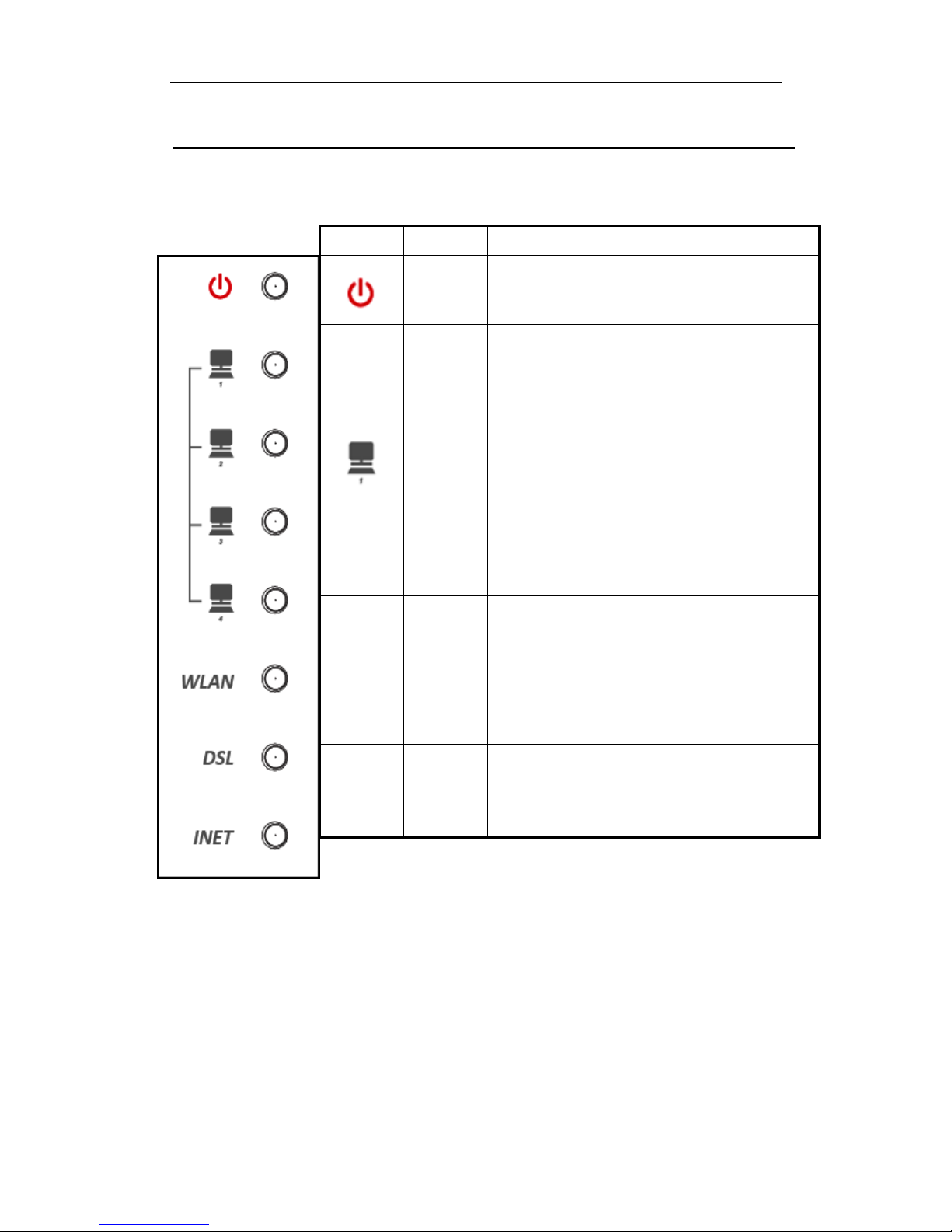
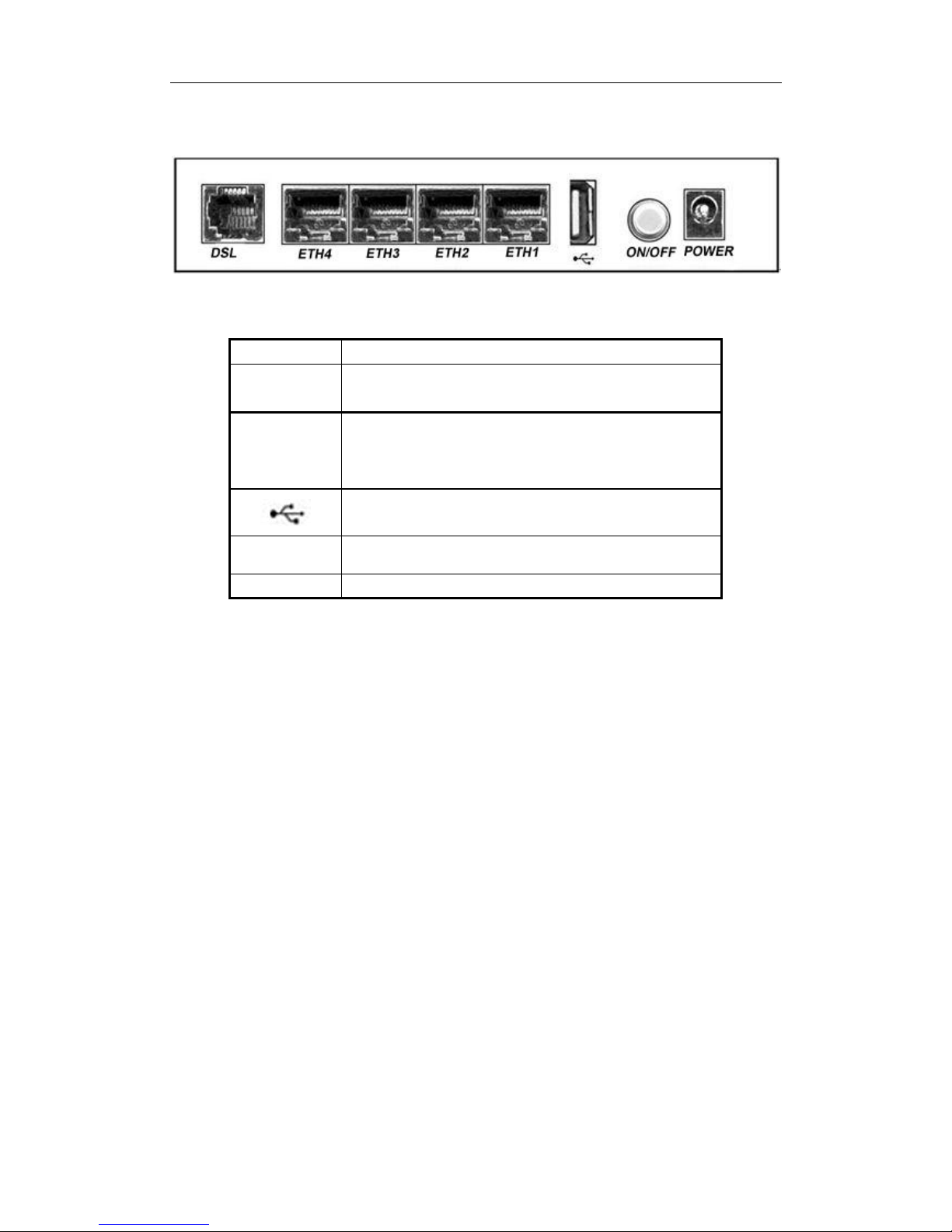
2 HARDWARE DESCRIPTION ................................................................................................ 5
3HARDWARE INSTALLATION.............................................................................................. 7
4PC CONFIGURATION GUIDE ............................................................................................. 8
4.1 LOCAL PC CONFIGURATION IN WINDOWS 95, 98, ME, XP,7 ............................................8
4.2 LOCAL PC CONFIGURATION IN WINDOWS 2000 .................................................................8
5 WEB-BASED MANAGEMENT GUIDE ............................................................................... 9
5.1 LAN SETTING PAGE............................................................................................................9
5.2 INTERNET ACCESS CONFIGURATION .............................................................................10
5.2.1 ADSL Setup ........................................................................................................ 10
5.2.2 VDSL Setup ........................................................................................................ 15
5.2.3 Router Mode Setup ............................................................................................. 19
5.2.4 LAN Settings ...................................................................................................... 25
5.3 WIRELESS SETTING ..........................................................................................................27
5.3.1 Basic .................................................................................................................... 27
5.3.2 Security ............................................................................................................... 28
5.4 PRINTER SERVER INSTALLATIONS ...................................................................................31
6. QOS SETUP........................................................................................................................... 33
APPENDIX : FREQUENT ASKED QUESTIONS................................................................ 43

WLAN VDSL Router User Manual
1
1 Overview
Thank you for choosing our product. The product is a Wireless VDSL router combining an
VDSL modem, an 802.11n wireless router ,a 4-port switch and an USB port in one unit,
bringing high-speed wireless Internet connection to a home or office.
1.1 Features
1.1.1 Data Rate
Downstream data rate up to 100 Mbps
Upstream data rate up to 50Mbps
1.1.2 VDSL Compliant
ITU G.992.1 (G.DMT)
ITU G.993.2 (G.vdsl2) (Profile 8a, 8b, 8c, 8d, 12a,12b and 17a)
ITU G.992.2 (G.Lite)
ITU G.994.1 (G.hs)
ITU G.992.3 (G.DMT.BIS)
ITU G.992.4 (G.lite.bis)
ITU G.992.5
Compatible with all T1.413 issue 2 (full rate DMT over analog POTS),
and CO DSLAM equipment
1.1.3 Wireless
Fully IEEE 802.11n compatible.
Wireless data rate up to 300Mbps
Operating in the unlicensed 2.4 GHz ISM band
Multi-SSID
Supports 64/128 bits WEP security and user authentication
1.1.4 Network Protocol & Features
Ethernet to ADSL Self-Learning Transparent Bridging
Internet Control Message Protocol (ICMP)

WLAN VDSL Router User Manual
2
IP Static Routing
Routing Information Protocol (RIP, RIPv2)
Network Address Translation (NAT)
Virtual Server, Port Forwarding
Dynamic Host Configuration Protocol (DHCP)
DNS Relay, DDNS
IGMP Proxy
Simple Network Time Protocol (SNTP)
VPN pass-through (IPSec/PPTP/L2TP)
Parent control
1.1.5 ATM Capabilities
RFC 1483 Multi-protocol over ATM “Bridged Ethernet” compliant
RFC 2364 PPP over ATM compliant
RFC 2516 PPP over Ethernet compliant
ATM Forum UNI3.1/4.0 PVC –Support up to 16 PVCs
VPI Range: 0-255
VCI Range: 32-65535
UNI 3.0 & 3.1 Signaling
ATM AAL5 (Adaption Layer type 5)
OAM F4/F5
1.1.6 FIREWALL
Built-in NAT
MAC Filtering
Packet Filtering
Stateful Packet Inspection (SPI)
Denial of Service Prevention (DoS)

WLAN VDSL Router User Manual
3
DMZ
1.1.7 Management Support
Web Based GUI
Upgrade or update via FTP/HTTP
Command Line Interface via Telnet
Diagnostic Test
Firmware upgradeable for future feature enhancement
1.1.8 Operating System Support
WINDOWS 98/98 SE/ME/2000/XP/VISTA/7
Macintosh
LINUX
1.1.9 Environmental
Operating humidity: 10%-90% non-condensing
Non-operating storage humidity: 5%-95% non-condensing
1.2 Packet Contents
The packet contents are as the following:
VDSL ROUTER x 1
External Splitter x 1
Power Adapter x 1
Telephone Line x 1
Ethernet Cable x 1
Antenna x 2
Base x 1
CD x 1
1.3 System Requirements
Before using this ROUTER, verify that you meet the following requirements:

WLAN VDSL Router User Manual
4
Subscription for ADSL service. Your ADSL service provider should provide
you with at least one valid IP address (static assignment or dynamic
assignment via dial-up connection).
One or more computers, each contains an Ethernet 10/100M Base-T network
interface card (NIC).
A hub or switch, if you are connecting the device to more than one computer.
For system configuration using the supplied web-based program: A web
browser such as Internet Explorer v5.0 or later, or Netscape v4.7 or later.
1.4 Factory Defaults
The device is configured with the following factory defaults:
IP Address: 192.168.1.1
Subnet Mask: 255.255.255.0
Encapsulation: RFC 2516 LLC
VPI/VCI: According to local information
1.5 Warnings and Cautions
Never install telephone wiring during storm. Avoid using a telephone during an
electrical storm. There might be a risk of electric shock from lightening.
Do not install telephone jacks in wet locations and never use the product near
water.
To prevent dangerous overloading of the power circuit, be careful about the
designed maximum power load ratings. Not to follow the rating guideline could
result in a dangerous situation.
Please note that telephone line on modem must adopt the primary line that
directly outputs from junction box. Do not connect Router to extension phone.
In addition, if your house developer divides a telephone line to multi sockets
inside the wall of house, please only use the telephone that has connected with
the splitter of ADSL Router when you access the Internet.

WLAN VDSL Router User Manual
5
2 Hardware Description
Front Panel
LED
Color
Function
Green
On: Power on
Off: No power
Green
On: LAN link established and active via LAN port
Blinking: DSL data activity occurs
Off: No LAN link via LAN port
WLAN
Green
On: The wireless module is ready and idle
Blinking: Data transmitting or receiving over WLAN
Off: The wireless function is off
DSL
Green
On: DSL link established and active
Quick Blinking: DSLis trying to establish a connection
Slow Blinking: No DSL link
INET
Green
On: IP connected
Blinking: IP connected and IP traffic is passing thru
this device
Off: ADSL connnetion is not present

WLAN VDSL Router User Manual
6
Rear panel
Side panel
WIFI button: Enable or disable wireless function.
Reset button: System reset or reset to factory defaults.
WPS button: A convenient way for WPS set.
Port
Function
DSL
Connect the device to an DSL telephone jack or splitter
using a RJ-11 telephone cable
ETH1,2,3,4
Connect the device to your PC's Ethernet port, or to
the uplink port on your hub/switch, using a RJ-45
cable
Connect the device to a printer
ON/OFF
Switch it on or off
POWER
Connect to the supplied power adapter

WLAN VDSL Router User Manual
7
3 Hardware Installation
This chapter shows you how to connect Router. Meanwhile, it introduces the
appropriate environment for the Router and installation instructions.
1. Using a telephone line to connect the DSL port of ROUTER to the MODEM port
of the splitter, and using a other telephone line connect your telephone to the
PHONE port of the splitter, then connect the wall phone jack to the LINE port of
the splitter.
The splitter comes with three connectors as below:
LINE: Connects to a wall phone jack (RJ-11 jack)
MODEM: Connects to the DSL jack of ROUTER
PHONE: Connects to a telephone set
2. Using an Ethernet Cable to connect the LAN port of the ROUTER to your LAN or
a PC with network card installed.
3. Connect the power cable to the PWR connector on ROUTER, then plug in the
power adapter to the power outlet, and then press the on-off button.
Notes: Without the splitter and certain situation, transient noise from telephone
can interfere with the operation of the Router, and the Router may
introduce noise to the telephone line. To prevent this from happening, a
small external splitter must be connected to each telephone.

WLAN VDSL Router User Manual
8
4 PC Configuration Guide
4.1 Local PC Configuration in Windows 95, 98, ME, XP,7
1. In the Windows task bar, click the “Start” button, point to “Settings”, and then
click “Control Panel”.
2. Double-click the “Network” icon.
3. On the “Configuration” tab, select the TCP/IP network associated with your
network card and then click “Properties”.
4. In the “TCP/IP Properties” dialog box, click the “IP Address” tab. Set the IP
address as 192.168.1.x (x can be a decimal number from 2 to 254.) like
192.168.1.2, and the subnet mask as 255.255.255.0.
5. On the “Gateway” tab, set a new gateway as 192.168.1.1, and then click “Add”.
6. Configure the “DNS” tab if necessary. For information on the IP address of the
DNS server, please consult with your ISP.
7. Click “OK” twice to confirm and save your changes.
8. You will be prompted to restart Windows. Click “Yes”.
4.2 Local PC Configuration in Windows 2000
1. In the Windows task bar, click the “Start” button, point to “Settings”, and then
click “Control Panel”.
2. Double-click the “Network and Dial-up Connections” icon.
3. In the “Network and Dial-up Connections” window, right-click the “Local Area
Connection” icon, and then select “Properties”.
4. Highlight “Internet Protocol (TCP/IP)”, and then click “Properties”.
5. In the “Internet Protocol (TCP/IP) Properties” dialog box, set the IP address as
192.168.1.x (x can be a decimal number from 2 to 254.), and the subnet mask as
255.255.255.0 and the default gateway as 192.168.1.1. Then click “OK”.
6. Configure the “DNS” tab if necessary. For information on the IP address of the
DNS server, please consult with your ISP.
7. Click “OK” twice to confirm and save your changes.

WLAN VDSL Router User Manual
9
5 Web-based Management Guide
In order to use the web-based management software it will be necessary to use a
computer that occupies the same subnet as the Router. The simplest way to do this for
many users will be to use DHCP server that is enabled by default on the Router.
5.1 LAN setting page
Launch a web browser, such as Internet Explorer, and then use http://192.168.1.1 to log
on to the setting pages.
After log on ,you will see the following screen :
Click OK
Enter username
‘admin’and password
‘adslroot’

WLAN VDSL Router User Manual
10
We can select wizard setup or advanced setup mode to setup KW5212.the wizard set up will
guide us for a basic setting,and the advanced setup will guide us to home page for more
detailed setup.
5.2 Internet Access Configuration
5.2.1 ADSL Setup
From home page, you can find Advanced Setup option on the left router configuration
page.
1. From Layer2 Interface, click ATM Interface. you can set it up according to the
following steps. You Choose Add, or Remove to configure DSL ATM interfaces.
2. Click Add to configure PVC identifier, select DSL latency and select connection
mode according to your local occasion. After the configuration, you need to click
Apply/Save.
3. Click WAN Service from the left menu.

WLAN VDSL Router User Manual
11
4. Click Add to select a layer 2 interface for this service and then click Next.
5. Choose WAN service type, just choose PPPoE for example here. You can enter your
own service description here if you want and then click Next.
6. Input PPP Username & PPP Password and then click Next. The user interface
allows a maximum of 256 characters in the user name and a maximum of 32
characters in the password.

WLAN VDSL Router User Manual
12
PPPoE service name can be blank unless your Internet Service Provider gives you a value to
enter.
Authentication method is default to Auto. It is recommended that you leave the
Authentication method in Auto, however, you may select PAP or CHAP if necessary. The
default value for MTU (Maximum Transmission Unit) is 1500 for PPPoA and 1492 for
PPPoE. Do not change these values unless your ISP asks you to.
Enable Full Cone NAT: In full cone NAT, all requests from the same private IP address and
port are mapped to the same public source IP address and port. Someone on the Internet only
needs to know the mapping scheme in order to send packets to a device behind the VDSL
Device.

WLAN VDSL Router User Manual
13
The gateway can be configured to disconnect if there is no activity for a specific period of
time by selecting the Dial on demand check box and entering the Inactivity timeout. The
entered value must be between 1 minute and 4320 minutes.
Use Static IPv4 address: If the ISP gave you a static (fixed) IP address, select this option and
enter it in the IP Address field. If the ISP did not give you a static IP address, clear the Use
Static IP Address option. The ISP automatically assigns the WAN connection an IP address
when it connects.
Enable PPP Debug Mode: Select this to turn on the debug mode for the PPP connection.
Bridge PPPoE Frames Between WAN and Local Ports: In addition to the VDSL Device's
built-in PPPoE client, you can enable this to pass PPPoE through in order to allow LAN hosts
to use PPPoE client software on their computers to connect to the ISP via the VDSL Device.
Each host can have a separate account and a public WAN IP address. PPPoE pass through is
an alternative to NAT for applications where NAT is not appropriate. Disable PPPoE pass
through if you do not need to allow hosts on the LAN to use PPPoE client software on their
computers to connect to the ISP.
The PPP IP Extension is a special feature deployed by some service providers. Unless your
service provider specifically requires this setup, do not select it. If you need to select it, the
PPP IP Extension supports the following conditions:
It allows only one computer on the LAN.
The public IP address assigned by the remote using the PPP/IPCP protocol
is actually not used on the WAN PPP interface. Instead, it is forwarded to
the computer's LAN interface through DHCP. Only one system on the
LAN can be connected to the remote, since the DHCP server within the
ADSL gateway has only a single IP address to assign to a LAN device.
NAPT and firewall are disabled when this option is selected.
The gateway becomes the default gateway and DNS server to the computer
through DHCP using the LAN interface IP address.
The gateway extends the IP subnet at the remote service provider to the
LAN computer. That is, the PC becomes a host belonging to the same IP
subnet.
The ADSL gateway bridges the IP packets between WAN and LAN ports,
unless the packet is addressed to the gateway's LAN IP address.
7. Select a preferred wan interface as the system default gateway.

WLAN VDSL Router User Manual
14
8. Get DNS server information from the selected WAN interface or enter static DNS server
IP addresses. If only a single PVC with IPoA or static MER protocol is configured, you
must enter static DNS server IP addresses.
9. Make sure that the settings below match the settings provided by your ISP. Click on the
Apply/Save button to save your configurations.

WLAN VDSL Router User Manual
15
5.2.2 VDSL Setup
From home page, you can find Advanced Setup option on the left router configuration
page.
1. From Layer2 Interface, click PTM Interface. you can set it up according to the
following steps. You Choose Add, or Remove to configure DSL PTM interfaces.
2.Click Add to configure PTM Priority, select DSL latency and select connection mode
according to your local occasion. After the configuration, you need to click Apply/Save.
3. Click WAN Service from the left menu.
4.Click Add to select a layer 2 interface for this service and then click Next.
5. Choose WAN service type, just choose PPPoE for example here. You can enter your
own service description here if you want and then click Next.

WLAN VDSL Router User Manual
16
6. Input PPP Username & PPP Password and then click Next. The user interface
allows a maximum of 256 characters in the user name and a maximum of 32 characters
in the password.

WLAN VDSL Router User Manual
17
PPPoE service name can be blank unless your Internet Service Provider gives you a value to
enter.
Authentication method is default to Auto. It is recommended that you leave the
Authentication method in Auto, however, you may select PAP or CHAP if necessary. The
default value for MTU (Maximum Transmission Unit) is 1500 for PPPoA and 1492 for
PPPoE. Do not change these values unless your ISP asks you to.
Enable Full Cone NAT: In full cone NAT, all requests from the same private IP address and
port are mapped to the same public source IP address and port. Someone on the Internet only
needs to know the mapping scheme in order to send packets to a device behind the VDSL
Device.
The gateway can be configured to disconnect if there is no activity for a specific period of
time by selecting the Dial on demand check box and entering the Inactivity timeout. The
entered value must be between 1 minute and 4320 minutes.
Use Static IPv4 address: If the ISP gave you a static (fixed) IP address, select this option and
enter it in the IP Address field. If the ISP did not give you a static IP address, clear the Use
Static IP Address option. The ISP automatically assigns the WAN connection an IP address
when it connects.
Enable PPP Debug Mode: Select this to turn on the debug mode for the PPP connection.
Bridge PPPoE Frames Between WAN and Local Ports: In addition to the VDSL Device's
built-in PPPoE client, you can enable this to pass PPPoE through in order to allow LAN hosts
to use PPPoE client software on their computers to connect to the ISP via the VDSL Device.
Each host can have a separate account and a public WAN IP address. PPPoE pass through is
an alternative to NAT for applications where NAT is not appropriate. Disable PPPoE pass
through if you do not need to allow hosts on the LAN to use PPPoE client software on their
computers to connect to the ISP.
The PPP IP Extension is a special feature deployed by some service providers. Unless your
service provider specifically requires this setup, do not select it. If you need to select it, the
PPP IP Extension supports the following conditions:
It allows only one computer on the LAN.
The public IP address assigned by the remote using the PPP/IPCP protocol
is actually not used on the WAN PPP interface. Instead, it is forwarded to
the computer's LAN interface through DHCP. Only one system on the
Other manuals for KW5212
1
Table of contents
Other Kasda Wireless Router manuals