Kassel Sanitar RONDA N DP Series Quick start guide

RONDA N DP / RONDA N DÚO DP SERIES
WALL MOUNTED ELECTRONIC FAUCET
OPERATION AND INSTALLATION GUIDE

1
TECHNICAL DATAINDEX
Power supply: 9V battery or 9V transformer
Recommended water
pressure:
0.5-8.0 bar (7-116 PSI)
With water pressure of more than 8 bars,
use a pressure reducing valve for reduction
Sensor range: Self-adjusting sensor
Adjustable with optional remote control
Minimum sensor range: 35mm / 1.38”
Maximum sensor range: 300mm / 11.81”
Security time: 90 seconds. Can be reduced with optional
remote control
Hot water temperature: Max. 70ºC
RONDA N DP RONDA N DÚO DPKSL00177 KSL00174
The information in this document reflects products at the date of printing. Kassel Sanitar, S.L. reserves the right, subject to all applicable laws, at any time, at its
sole discretion, and without notice, to discontinue or change the features, designs, materials and other specifications of its products, and to either permanently or
temporarily withdraw any of the forgoing from the market. All information in this document is provided “as is” without warranty of any kind, either expressed or
implied, including but not limited to any implied warranties of merchantability, fitness for a particular purpose, or non-infringement. Kassel Sanitar, S.L. assumes
no responsibility for errors or omissions in the information presented in this document. In no event shall Kassel Sanitar, S .L. be liable for any special, incidental,
indirect or consequential damages of any kind, or any damages whatsoever arising out of or in connection with the use or performance of this information.The
trade names, trademarks, logos and service marks presented in this document, including their design, are the property of Kassel Sanitar, S.L. or other third parties
and you are not permitted to use them without the prior written consent of Kassel Sanitar, S.L. or such third party as may own them.
1 TECHNICAL DATA
2 -3 PACK CONTENTS
4 PRE-INSTALLATION INFORMATION
5-8 INSTALLATION
9-11 SETTINGS ADJUSTMENT
12-13 BATTERY REPLACEMENT INSTRUCTIONS
14 MAINTENANCE
15 LIMITED WARRANTY
16 TROUBLESHOOTING

3
2
PACK CONTENTS PACK CONTENTS
RONDA N DP RONDA N DÚO DP
1 x Spout and
attachments (incl.
electronic unit)
M 4 x 4 set screw
M 4 x 4 set screw
1 x Wall rosette
1 x Wall rosette
1 x base
1 x base
1 x CorrugatedTube
1 x CorrugatedTube
1 x Dual
power
input box
with inlet
nipple and
filter
2 x waterproof solenoid
housing with inlet nipple
and filter
BATTERY VERSION
MAINS VERSION
1 x Dual power
input box with
inlet nipple and
filter
1 xTransformer
OPERATION
This faucet features an IP67 dual power input box.
The product can be operated with a 9V battery or
a 9V transformer. In addition, when used with a
transformer the product contains an integrated
battery backup, for normal use during power supply
failures.
MAINS VERSION
9VTRANSFORMER
BATTERY VERSION
BATTERY BOX FOR
6 X 1.5V AA BATTERIES

5
4
PRE-INSTALLATION INFO INSTALLATION
CHECK CONTENTS
Separate all parts from the packaging and check each part with the pack
contents section. Pay attention to the variations of the different models.
Make sure all parts are accounted for before discarding any packaging
material.
If any parts are missing, do not attempt to install your electronic faucet until
you obtain the missing parts.
WARNING
1)To avoid reflection problems keep
a distance of more than 300 mm.
between the sink and the spout.
2)This faucet model, with an infrared
sensor pointing down, is not
intended to be used together with a
sink of a reflective material such as
stainless steel.
3) If a sink strainer is straight below
the faucet sensor, use a strainer with
a non reflective finish (do not use a
chrome plated one).
Min 300 mm.
Bottom of the washbasin
PREPARATION FOR INSTALLATION
Flush the water supply lines thoroughly before installing the
faucet. Do not allow dirt, teflon tape or metal particles to enter the
faucet. Shut off water supply.
IMPORTANT
All plumbing is to be installed in accordance with applicable codes
and regulations.
Installations in Australia and New Zealand must comply with the
requirements of AS/NZS 3500.
STEP 1 – INSTALLING THE FAUCET
1Shut off the water supply.
ONE INLET TWO INLETS
2
Cut an adequate opening in
the wall for the dimensions
of the product base, and the
corrugated tube.
3Dismantle the faucet base.
4Drill 4 small holes for the
product base support and
drive the anchors in.
80mm
80mm

7
6
FAUCET INSTALLATION FAUCET INSTALLATION
5
Mount the product base to
the opening cut in the wall,
and secure the base support
to the four small holes using
4 screws. Make sure that the
base is leveled to the center.
IMPORTANT:The product base should
be installed so that the outside surface
of the finished wall falls between the
minimum and maximum lines marked
at the base.
MINMAX
6Assemble the temporary
protective product base cover.
7Make sure the corrugated tube
will protrude out of the wall
when tiling.
CORRUGATED TUBE
8Cut the temporary product base
cover.
9
Once the works on electricity,
plumbing and tiles have been
finished, assemble the wall rosette
through the product base.
WALL ROSETTE
10
Pull the sensor wire/s out of
the product base, and lead it/them
along with the flexible tube/s,
through the corrugated tube.
FLEXIBLE
TUBE
11 Connect the flexible tube/s to
the dual power input box quick
connection outlet/s.
12 Fix the product spout by inserting
the nipple into the product base
and tighten the screw.
STEP 2 - CONNECTING THE WATER SUPPLY
IMPORTANT:This product was supplied with a self adjusting sensor.The ideal
sensor range for the specific location will be set automatically.
OBJECT
Before proceeding, check that no objects are
in front of the sensor besides the washbasin. Now, remove the protective sticker
that covers the sensor.

9
8
FAUCET INSTALLATION SETTINGS ADJUSTMENT
1
If your model is RONDA N DP powered by battery a 9V battery is
already installed in the dual power input box.
If your model is RONDA N DUO DP powered by battery: Connect the
other cable coming from the electronic unit at the product base to the
battery box.
If your model is RONDA N DP
powered by transformer, connect
the transformer to the transformer
socket in the dual power input box
and plug it into the electricity socket.
If your model is RONDA N DUO DP
powered by transformer, connect
the cable coming from the electronic
unit from the product base to the
transformer connector. Plug the
transformer into the electricity
socket.
FROM THE ELECTRONIC UNIT
TO THE POWER SUPPLY
2
For RONDA N DP models:
Connect the four contacts connector
to the dual power input box.
Important: Make sure that the 4
contacts connector is connected all
the way through.
O-RING VISIBLE –
NOT CONNECTED PROPERLY
ONLYTHE GROOVES AREVISIBLE –
CONNECTED PROPERLY
3
After you have connected the four
contacts connector to the dual power
input box, wait 15 seconds in order
to allow the system to set the ideal
sensor range. SECONDS
ABOUT
15
As an indication that the self adjusting has taken place a LED in the sensor eye
will flash continuously.The solenoid valve will open and close for 1 second as
an indication that the ideal sensor range is set and the product is ready for use.
4
Turn on the central water supply and
Check for leaks.
If the automatically adjusted sensor
range is not satisfactory, please
refer to the section entitled “Settings
adjustment”. ONE INLET TWO INLETS
DETECTION
RANGE
DELAY INTIME
SECURITYTIME
COMFORT
FLUSH
DELAY OUTTIME
TEMPORARY OFF
FUNCTION
RESET
SELF ADJUSTMENT
MODE
HYGIENE FLUSH
Adjusting the settings with the remote control
If necessary, the sensor settings can be adjusted as following:
Shut off the water supply. In order to adjust the sensor with the remote control,
hold the remote control straight in front of the sensor in a distance of about
6-8” (15-20cm). Choose the function you want to adjust by pressing once on
one of the function buttons. After pressing once on a specific function button, a
quick flashing of the LED at the front of the sensor will occur. At this stage, you
can change the setting by pressing the (+) or the (-) buttons, every push will
increase or decrease one level. After finishing the adjustment, turn the water
supply back on.

11
10
SETTINGS ADJUSTMENTSETTINGS ADJUSTMENT
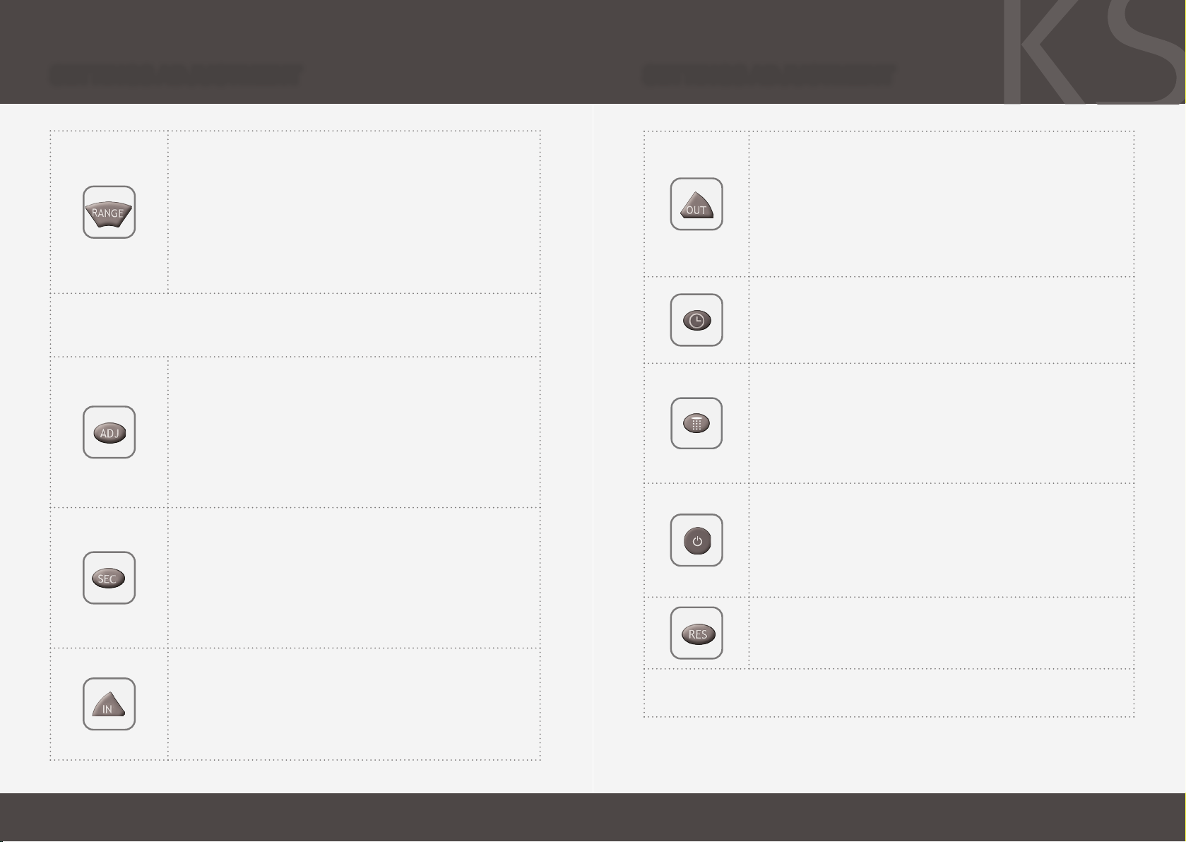
DETECTION RANGE: This faucet was supplied with a self
adjusting sensor.The ideal detection range for the specific
location will be set automatically.
Only if necessary, use the remote control to adjust the sensor
range as follows:
Press the RANGE button. Wait until a quick flashing of the LED
in the sensor eye is perceived.Then, press + to increase the
range and – to reduce it. Every push will increase or decrease
one level.
Note: Once you have changed the detection range with the remote control,
the distance will be remembered by the sensor, even if the power source is
disconnected.To get back to the self adjustment mode, use the ADJ button only.
ENTRANCETOTHE SELF ADJUSTMENT MODE: Check that no
objects are in front of the sensor. Press the ADJ button. Once
a quick flashing of the LED of the sensor eye is perceived,
remove your hand holding the remote control and move away
from the sensor area.The ideal sensor range for the specific
location will be set automatically. Once the self adjustment has
taken place, the solenoid valve will be opened and closed for 1
second as an indication that the ideal sensor range was set and
the product is ready for use.
SECURITYTIME:The Security time, prevents continuous
running of water due to reflections or vandalism. By default,
if the sensor is covered for more than 90 seconds the water
flow will shut automatically.To resume regular operation any
obstruction must be removed.
Press the SEC button. Wait until a quick flashing of the LED
in the sensor eye is perceived.Then, press + to increase the
security time and – to reduce it.
DELAY INTIME: It is recommended to change the delay in
time for flush valves for urinals or toilets only.
If required, the delay in time can also be modified in faucets
as follows:
Press the IN button. Wait until a quick flashing of the LED in
the sensor eye is perceived.Then, press + to increase the
delay in time and – to reduce it.
DELAY OUTTIME:This button allows modifying the water
flow time after the user removes his hands from the
faucet. A delay out time close to 0 will save more water.
An increased delay out time will make the user experience
more comfortable.
If required, the delay out time can be modified as follows:
Press the OUT button. Wait until a quick flashing of the LED
in the sensor eye is perceived.Then, press + to increase the
delay out time and – to reduce it.
24 HOUR HYGIENE FLUSH:This model includes a 24 hours
hygiene flush which is disabled.To activate the hygiene flush,
press the clock button. Wait until a quick flashing of the LED
in the sensor eye is perceived.Then press + to activate the
hygiene flush.To disable it again, press – to deactivate it.
COMFORT FLUSH: If your model includes a Comfort flush
setting, it can be activated by pressing the flush button.
When the button is pressed, one blink of the LED in the
sensor eye is perceived.The pre-programmed flush cycle will
take place then.
The Comfort flush cannot be interrupted or deactivated by
pressing any button until it is over.
TEMPORARY OFF FUNCTION:This function is ideal to
perform any kind of activity in front of the sensor without
operating the system (for example, cleaning).
The faucet will remain shut for 1 minute when this button
is pressed once.To cancel this function and to return to
normal operation press the On/Off button again or wait 1
minute.
RESET BUTTON:This function restores all the factory
settings except for the sensor range. If required, press the
Reset button and without releasing it, press the + button
once.
NOTE: To enter the self adjusting mode, use the ADJ button.To change the
sensor range, use the RANGE button.

13
12
.Remove the old batteries .Carefully open the battery box. Unscrew the holding screw
. Close the box
. Replace the used batteries
with a new X .V batteries (Lithium
battery is recommended).
New Battery
Old Battery
BATTERY REPLACEMENT BATTERY REPLACEMENT
BATTERY MODELS ONLY
When the battery weakens, the LED indicator light will blink at a constant rate when
the user’s hands are within the sensor range.The battery must be replaced within two
weeks.
TO REPLACETHE BATTERY:
FOR RONDA N DP: Carefully open the dual power input box, using the Allen key
provided. Remove the old battery and replace it with a new 9V battery (Lithium
battery is recommended). Close the box.
FOR RONDA N DUO DP: When the battery weakens, the LED indicator light will blink
at a constant rate.The battery must be replaced within two weeks.
IMPORTANT:These models were supplied with a self adjusting sensor.
The ideal sensor range for the specific location will be set automatically again after
changing the battery.
SECONDS
ABOUT
15
OBJECT
After you have replaced the battery,
move away from the sensor range.
Wait 15 seconds in order to allow the
system to set the ideal sensor range.
Then after the self adjustment has
taken place the solenoid valve will be
opened and closed for 1 second as an
indication that the ideal sensor range
was set and the product is ready for
use.
Check that there are no objects in front
of the sensor after the battery replace-
ment was completed.
IMPORTANT: Spent batteries should not be disposed of with
normal household waste. Contact your local authority for infor-
mation on waste disposal and recycling.

15
14
MAINTENANCE LIMITEDWARRANTY
KASSEL SANITÄR S.L. warrants that its electronic products will be free of defects in
material and workmanship during normal use for two years from the date the product is
purchased.
If a defect is found in normal use, KASSEL SANITÄR S.L. will, at its discretion, repair,
provide a replacement part or product, or make appropriate adjustments. Damage caused
by accident, misuse, or abuse is not covered by this warranty. Improper care and cleaning
will void the warranty. Proof of purchase (original sales receipt) must be provided to
KASSEL SANITÄR S.L. with all warranty claims.
KASSEL SANITÄR S.L. is not responsible for labor charges, installation, or other incidental
or consequential costs other than those noted above. In no event shall the liability of
KASSEL SANITÄR S.L. exceed the purchase price of the product.
If you believe that you have a warranty claim, contact your Kassel Distributor, Dealer
or Plumbing Contractor. Please be sure to provide all pertinent information regarding
your claim, including a complete description of the problem, the product, model number,
the date the product was purchased, from whom the product was purchased and the
installation date. Also include your original invoice.
KASSEL SANITÄR S.L. AND/OR SELLER DISCLAIM ANY LIABILITY FOR SPECIAL,
INCIDENTAL OR CONSEQUENTIAL DAMAGES. This warranty excludes product damage
due to installation error, incorrect maintenance, wear and tear, battery, product abuse, or
product misuse, whether performed by a contractor, service company, or the consumer.
This warranty does not cover product damage caused by the following:
- Incorrect installation.
- inversions of supply pipes.
- Pressures or temperatures exceeding recommended limits.
- Improper manipulation, tampering, bad or lapsed maintenance.
- Foreign bodies, dirt or scale introduced by the water supply or soap tank.
- Use of the soap outside of viscosity specifications.
- Alteration of the original soap/foam dispenser components (including pipes).
If system chemical disinfection is practiced, chlorine can be used (calculated
chlorine concentration of 50mg/l maximum in water per one hour dwell time)
at service interval frequency.
FILTER CLEANING INSTRUCTIONS
These models are provided with a stainless steel filter preventing foreign particles
to enter the lines. It is recommended to clean the filter every six (6) month. If the
water flow has decreased, this may be because the filter is clogged.The filter can
be cleaned as follows:
a. Shut-off the water shut off valve.
b. Disconnect the water supply pipe from the adaptor and disassemble the filter.
c. Wash the filter under running water.
d. Reassemble the parts.
e. Restore the incoming water supply and make sure that there is no water
leakage.
SOLENOID VALVE SERVICING
The solenoid valve diaphragm requires periodical cleaning every six (6) month.
Remove the diaphragm from the solenoid valve and examine it for dirt. in case it
is dirty or clogged, wash it under running water and reassemble it.
Do not attempt to dismantle the solenoid valve if you are unfamiliar with
electronic solenoid valves.
CARE AND CLEANING OF CHROME AND SPECIAL FINISHES
DO NOT use steel wool or cleansing agents containing alcohol, acid, abrasives, or
the like. Use of any prohibited cleaning or maintenance products or substances
could damage the surface of the faucet. For surface cleaning of faucet us ONLY
soap and water, then wipe dry with clean cloth or towel. When cleaning bathroom
tile, the faucets should be protected from any splattering of harsh cleansers.

17
16
TROUBLESHOOTING
* “Security Mode”: If the sensor is covered for more than 90 sec. the faucet will automatically shut off
water flow.
To return to normal operation remove any blockage.
** In this case, the water flow will stop anyway after 90 seconds because of the security time.
SOLUTIONCAUSEINDICATORPROBLEM
Replace batteryLow battery.
1.Sensor
flashes con-
tinuously when
user’s hands
are within the
sensor’s range.
No water
coming
out of the
faucet:
Increase the range1. Range is too short.
2. LED in the
sensor does
not flash once
when user’s
hands are
within the sen-
sor’s range.
Decrease the range2. Range is too long.
The battery must be re-
placed.
3. Battery is completely used up
4. Unit is in “Security Mode”*
Eliminate cause of reflection.
5. Sensor is picking up reflections from
the washbasin or another object.
Unscrew solenoid, pull out
the plunger and the spring
from the solenoid and clean
them. Use scale remover
material if needed. When
replacing the plunger, please
make sure that the spring is
in vertical position.
1. Debris or scale in solenoid.
3. LED in the
sensor flashes
once when
user’s hands
are within the
sensor’s range.
Clean the orifice or replace
diaphragm.
2.The central orifice in the diaphragm is
plugged or the diaphragm is torn
Reduce the supply water
pressure.
3.The water supply pressure is higher
than 8 bar.
Shut off water supply and
unscrew one of the flexible
pipes in order to reduce
the pressure that blocks the
product.
4.The water supply pressure is under 8
bars and yet the pressure in the faucet’s
body is higher.This situation could be
caused by a sudden increase in the
water supply pressure that the backcheck
prevents from dropping, even after water
supply pressure drops under 8 bars.
Clean the orifice or replace
diaphragm.
1. Debris or scale in diaphragm
1. Sensor
flashes once
when user’s
hands are
within the sen-
sor’s range.
Water flow
from spout
does not
stop: Connect the connectors
properly. Refer to pages
8/13/17 to see how.
2. Connectors between the electronic unit
and the Dual power input box are discon-
nected or not connected properly
Clean or eliminate case of
interference.
1. Sensor is dirty or covered.**
2. LED in the
sensor does
not flash once
when user’s
hands are
within the sen-
sor’s range.
Decrease the range or elimi-
nate cause of reflection.
2. Sensor is picking up reflections from
the washbasin or another object.
Remove, clean, re-installFilter or aerator is clogged
Water flow
diminished

KSL01208 12/2019
Kassel Sanitär S.L.
•Avda. de Castilla, 1 - Polígono Industrial, 28830 San Fernando de Henares, Madrid, Spain
•
Daimlerstraße 2, D-93133 Burglengenfeld, Germany
This manual suits for next models
1
Table of contents
Other Kassel Sanitar Plumbing Product manuals
Popular Plumbing Product manuals by other brands

Viega
Viega 8351.65 Instructions for use

Dornbracht
Dornbracht 26 023 661-FF installation instructions

Sentiotec
Sentiotec ARKTIS INFRA + Instructions for installation and use

Delta
Delta 28996LF manual

American Standard
American Standard One 2064.461 installation instructions

Bristan
Bristan JAVA J BSM E8 C Fitting instructions

HOLL'S
HOLL'S Hybrid Combi HL-HC04-RS Installation handbook

Hans Grohe
Hans Grohe Solaris Specification sheet

Toto
Toto WT151M Installation and owner's manual

Pfister
Pfister Zanna F-529-7ZN3 Quick installation guide

Symmons
Symmons Duro 361SH Operation & maintenance manual

Graff
Graff 7080 installation instructions