Kathrein SAT IP 414/E User manual

1 / 9
EXIP 414/E 20510103
SAT>IP-Server
Merkmale
Unterstützt das SAT>IP-Protokoll
Entspricht dem SAT>IP-Standard nach
EN 50585
Streamt DVB-S-/S2(HDTV)-Signale in
einen IP-Datenstrom
Einspeisung in verschiedene Netz-
werktypen möglich: LAN (auch K-LAN,
Powerline ...), WLAN-Einbindung über
Router, z. B. FRITZ!Box, möglich
Vier unabhängige Tuner für je einen
Datenstrom
Web-Interface zur Konguration,
Administration und zur Einspielung
von Software-Updates
Statusanzeige über LED
Unterschiedliche Clients
1)
möglich:
Tablet PCs, Smartphones, Notebooks,
SAT>IP-fähige Receiver (z. B. UFS 924)
Ein-/Ausschalter
Betrieb an verschiedenen Arten von
LNBs, Multischaltern und Einkabel-
Multischaltern möglich
Unterstützt die gängigen Schaltsignale:
14/18 V, 22 kHz, DiSEqC™1.0,
Einkabel nach EN 50494
Vier Sat-Eingänge; ein Ethernet-
RJ 45-Anschluss
Zur horizontalen Aufstellung
(wie z. B. bei einem Receiver) oder
Wandmontage mit mitgeliefer-
ter Montagehalterung geeignet
Für die Innenmontage
Efzientes Steckernetzteil zur
Spannnungsversorgung
Kabelschuh für Erdungsanschluss
Halterung für Wandmontage
Anwendungshinweis
1) Entsprechende Software/Apps auf dem jeweiligen Gerät vorausgesetzt
Lieferumfang
(Zertiziert durch SES ASTRA)
Vous trouverez la
version française du
document sur:
Una versione italiana
di questo documen-
to è reperibile su:
Encontrará la version
española de este docu-
mento en la página:
www.kathrein.com

2 / 9
• Das beschriebene Gerät dient ausschließlich der Installation in Satelliten-
Empfangsanlagen - jegliche anderweitige Nutzung oder die Nichtbeachtung
dieses Anwendungshinweises hat den Verlust der Gewährleistung bzw.
Garantie zur Folge.
• Das Gerät darf nur in trockenen Innenräumen montiert werden. Nicht auf
oder an leicht entzündlichen Materialien montieren.
• Das Steckernetzteil ist nur für die Wandmontage
zugelassen!
• Das Gerät ist mit einer Potenzial-Ausgleichsleitung
(Cu, mindestens 4 mm2) zu versehen.
• Nicht benützte F-Anschlüsse müssen mit einem EMK 05 (spannungsge-
trennt) abgeschlossen werden.
• Die Sicherheitsbestimmungen der jeweils aktuellen Normen EN 60728-11
und EN 60065 sind zu beachten.
• Verbindungsstecker für Koaxialkabel: HF-Stecker 75 Ω (Serie F) nach
EN 61169-24.
Stromführendes Gerät
• Nicht öffnen oder am Gerät manipulieren!
• Bei Arbeiten an der Anlage immer Steckernetzteil aus der Steckdose ziehen!
• Für die Geräteentwärmung muss freie Luftzirkulation möglich sein.
Überhitzungsgefahr! Nach allen Seiten mind. 5 cm Abstand!
• Zulässige Umgebungstemperatur: 0 bis +40°C
Achtung:
• Auf das Gerät sowie das Steckernetzteil dürfen keine mit Flüssigkeit
gefüllten Gegenstände gestellt werden.
• Das Gerät sowie das Steckernetzteil dürfen nicht Tropf- oder Spritzwasser
ausgesetzt werden.
• Das Steckernetzteil muss ohne Schwierigkeiten zugänglich und benutzbar
sein.
• Das Gerät kann nur durch Ziehen des Steckernetzteils komplett vom Netz
getrennt werden.
Montage- und Sicherheitshinweise
• Bei größerem Durchmes-
ser des Kabel-Innenleiters
als 1,2 mm bzw. Grat kön-
nen die Gerätebuchsen
zerstört werden.
Max. 2 mm
Überstand
Anzugsmoment max.
3,4 Nm (Gefahr des
Überdrehens)
Durchmesser
0,6-1,2 mm gratfrei

3 / 9
Wandmontage
• Verwenden Sie für die Wandmontage
nur die beiliegende Halterung (Schrau-
ben sind nicht im Lieferumfang enthalten)
Wandhalter mit zwei Schrauben (Ø 4 mm,
Kopfdurchmesser > 7 mm) montieren
• Alle Kabel anstecken/anschrauben
• Gerät mit den Füßen von oben in die
Wandhalterung einführen
• Tischmontage (keine Fixierung notwendig)
A B
(in MontagelageAsollte das Gerät bei nach-
träglicher Kabelmontage gehalten werden.
Damit wird verhindert, dass das Gerät even-
tuell aus der Halterung geschoben wird)

4 / 9
1 2
3 4 5 6 7 8 9 10
Oben am Gehäuse:
1. Stream-LED
2. Power-LED
Rückseite:
3. RF1-Eingang V low im Quatro-Mode;
Einkabel(EN 50494)-Anschluss
4. RF2-Eingang V high im Quatro-Mode
5. RF3-Eingang H low im Quatro-Mode
6. RF4-Eingang H high im Quatro-Mode
7. 10/100/1000-MBit-Ethernet
8. Reset-Taster
9. Ein-/Ausschalter
10. Netzteilanschluss (12 V/3 A)
Rückansicht
Inbetriebnahme
Gehen Sie bei der Inbetriebnahme des EXIP 414 wie folgend erklärt vor:
1.Anschluss der RF-Eingänge:
• An einem Quad-LNB oder Multischalter: Sie können die vier Eingangskabel wahlfrei
anschließen. Das Gerät ist für diesen Fall bereits vorkonguriert.
• An einem Quatro-LNB, Verteiler oder Abzweiger:
Sie müssen die vier Eingangskabel entsprechend der Spannungsbelegung (Tab 2) richtig
anschließen. Im Web-Interface muss unter „LNB Einstellungen“, „Quatro“ eingestellt sein.
• An einem Einkabel-Multischalter/Einkabel-LNB:
Es muss nur der Anschluss RF1 mit einem Multischalter oder LNB verbunden werden. Im
Web-Interface muss unter LNB Einstellungen, „OneCable“ und die verfügbaren UB-Slots
eingestellt werden

5 / 9
Übersicht LED
Tab 1 LED ... Status EXIP 414
„Power“ LED Leuchtet grün Betrieb
Ist aus Keine Spannungsversorgung
„Stream“ LED
Leuchtet blau Netzwerkverbindung hergestellt
Blinkt blau Aktives Streaming (Datentransfer)
Ist aus Netzwerk nicht angeschlossen
RF-Anschlüsse
Tab 2 Einkabel (EN 50494) Quatro Quad/DiSEqC™
RF1 (950-2150 MHz) 14/18 V; 0/22 kHz 14 V; 0 kHz 14/18 V; 0/22 kHz
RF2 (950-2150 MHz) 14 V; 22 kHz 14/18 V; 0/22 kHz
RF3 (950-2150 MHz) 18 V; 0 kHz 14/18 V; 0/22 kHz
RF4 (950-2150 MHz) 18 V; 22 kHz 14/18 V; 0/22 kHz
2.Anschluss Netzwerk:
Der LAN-Anschluss muss mit dem Heimnetzwerk verbunden werden. Im Normalfall wird
vom vorhandenen Router (z. B. FRITZ!Box) automatisch eine IP-Adresse vergeben.
Im Webinterface ist unter „IP-Einstellungen“ „Automatisch“ eingestellt (default).
3. Anschluss „DC“:
Als Letztes wird das Netzteil zuerst am Server und danach an die Netzspannung ange-
schlossen
Anwendung Spezikation
Ethernet Anschluss an das Netzwerk 10/100/1000 MBit
DC-Buchse Anschluss Steckernetzteil 12 V/3 A
Schalter/Taster wird ... Löst folgende Aktion aus ...
Reset Ca. fünf Sekunden gedrückt
gehalten Rücksetzen auf
Werkseinstellung
On/Off Gerät wird von der Spannungs-
versorgung getrennt
Weitere-Anschlüsse
Schalter und Taster

6 / 9
In den Netzwerk-Grundeinstellungen ist „Automatisch“ eingestellt. Das heißt, wenn der Ser-
ver an einem Router angeschlossen wird, bekommt er automatisch eine IP-Adresse zuge-
wiesen.
Der jeweilige Client (PC, App oder IP-Receiver) erkennt den Server per UPnP und es kann
eine Verbindung aufgebaut werden.
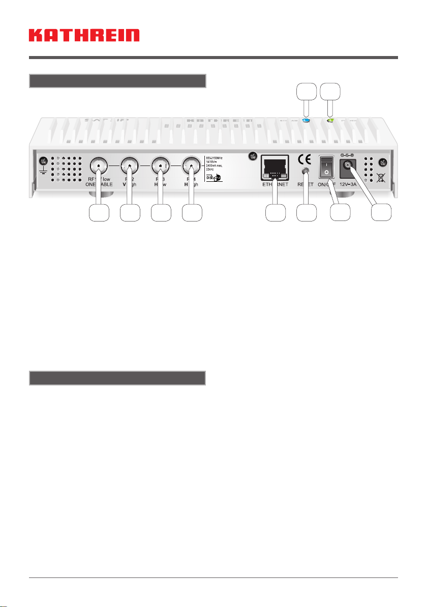
Die Satelliten-Grundeinstellung ist „Quad/DiSEqC™“. Jeder RF-Anschluss gibt ein
DiSEqC™- bzw. Analog-Schaltsignal aus, um das LNB- bzw. den Multischalter-Anschluss
auf das benötigte Band zu schalten.
Weitere Einstellungen können im Web-Interface des EXIP 414 vorgenommen werden. Dazu
geben Sie in Ihrem Web-Browser die IP-Adresse des EXIP 414 ein, gefolgt vom Port 9527,
z. B. 192.168.175.35:9527. Die IP-Adresse Ihres EXIP 414 nden Sie im Menü Ihres Rou-
ters. Alternativ kann die IP-Adresse mit einem Software-Utility bestimmt werden z. B. „Intel®
Tools for UPnP Technology“.
Nach Eingabe des Passwortes „exip“ gelangt man auf das Web-Interface.
Eine ausführliche Anleitung für das Web-Interface nden Sie unter „www.kathrein.de“.
Grundeinstellungen (Webinterface)
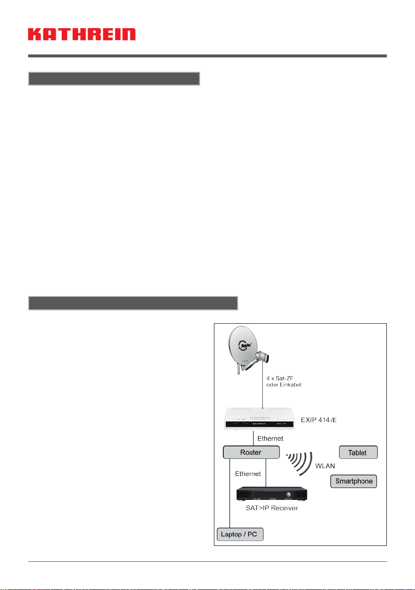
Der Datenstrom, der vom EXIP 414 in Ihr
Heimnetzwerk eingespeist wird, kann von
nahezu jedem beliebigen IP-fähigen Endge-
rät wiedergegeben werden. Neben bereits
SAT>IP-fähigen Receivern aus unserem
Haus, wie z. B. dem UFS 924, UFS 906,
UFS 916, ist bei vielen anderen Geräten
lediglich das Aufspielen einer SAT>IP-Soft-
ware nötig.
EineAuswahl an Software für PCs, Laptops,
Tablet-Computer und Smartphones nden
Sie auf unserer Website „www.kathrein.de”
unter der Produktbeschreibung des
EXIP 414.
Die Verknüpfung des EXIP 414 mit dem je-
weiligem SAT>IP-fähigen Endgerät entneh-
men Sie bitte der jeweiligen Software Doku-
mentation. Normalerweise sollte dies aber
aufgrund der UPNP-Schnittstelle weitestge-
hend automatisch erfolgen.
Anwendung
*)
*)
*)
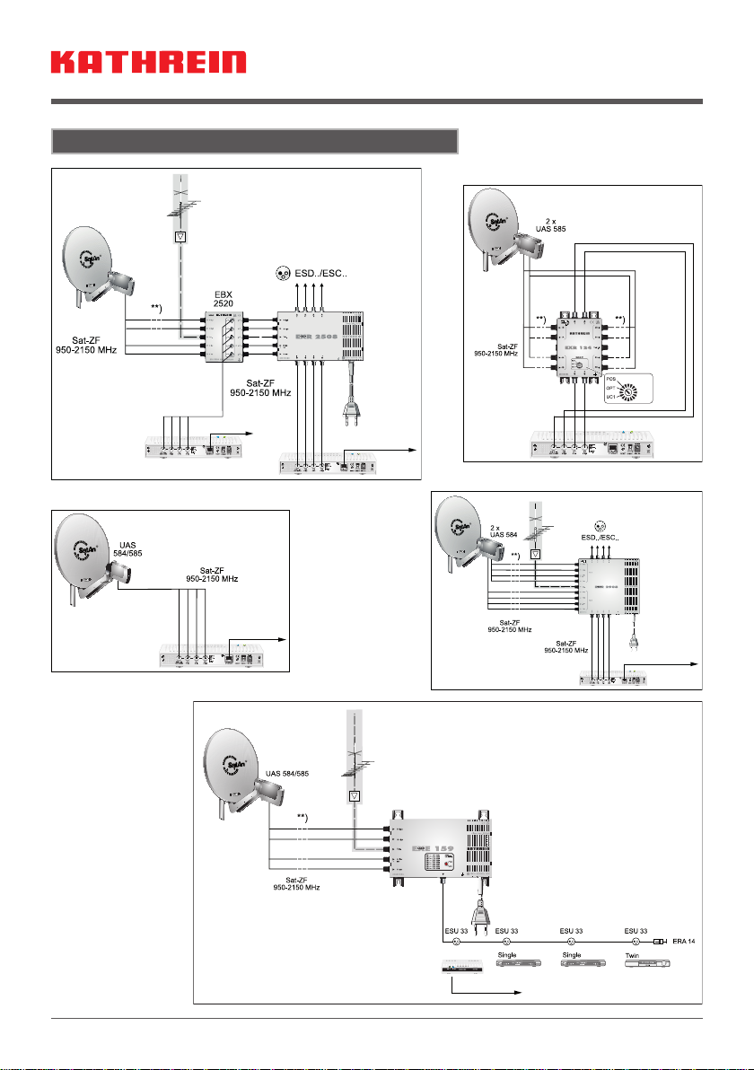
*) Pro Kanal werden bis zu 20 MBit/s
an Daten übertragen. Achten Sie
auf eine entsprechende Leistungs-
fähigkeit Ihrer Netzwerktechnik!

7 / 9
Problem Mögliche Ursache Fehlerbehebung
LED „Stream“
leuchtet nicht Keine Netzwerk-
verbindung Netzwerkkabel anschließen
LED „Power“
leuchtet nicht On/Off-Schalter
steht auf „off“ Überprüfen Sie den Schalter an der Rückseite
des Gerätes und stellen sie diesen auf „on“
LED „Power“
leuchtet nicht Netzteil nicht an-
geschlossen Stecken Sie das Netzteil am Server an und
verbinden Sie es mit dem 230-V-Netz
Mögliche Fehlerursachen und deren Behebung
Elektronische Geräte gehören nicht in den Hausmüll, sondern müssen -
gemäß Richtlinie 2002/96/EG DES EUROPÄISCHEN PARLAMENTS UND
DES RATES vom 27. Januar 2003 über Elektro- und Elektronik-Altgeräte
fachgerecht entsorgt werden. Bitte geben Sie dieses Gerät am Ende seiner
Verwendung zur Entsorgung an den dafür vorgesehenen öffentlichen Sam-
melstellen ab.

8 / 9
Anschlussbeispiele (Symbolische Darstellungen)
UAS 584
IP
IP
IP
IP
IP
EXIP 414/E
**) Überspannungs-
schutz KAZ 11/12

936.4910/-/VMWI/0215/DE – Technische Änderungen vorbehalten!
Internet: www.kathrein.com
KATHREIN-Werke KG • Anton-Kathrein-Straße 1-3 • Postfach 10 04 44 • 83004 Rosenheim • Deutschland • Telefon +49 (0) 8031 184-0 • Fax +49 (0) 8031 184-306
Typ EXIP 414/E
Bestell-Nr. 20510103
Teilnehmeranschlüsse 1 x 4
Frequenzbereich MHz 950 – 2150
Eingang 4 x Sat
Eingangspegelbereich dBµV 42 – 87
Impedanz Ω 75
Zul. Fernspeisespannung am Eingang V 12 – 20
Max. zulässiger Fernspeisestrom mA 400
Ausgangsspannung Horizontal V > 17,5 (bei 400 mA)/< 19 (bei 0 mA)
Ausgangsspannung Vertikal V > 12,5 (bei 400 mA)/< 14 (bei 0 mA)
Steuersignale 14/18 V, 22 kHz 0,6 Vpp (EN 61319-1),
DiSEqC™1.0 (EN 61319-1 A11),
Einkabel-System (EN 50494)
Leistungsaufnahme des Servers W typ. 12/min. 7
Zulässige Umgebungstemperatur °C 0 – +40
Anschlüsse F-Connectoren, RJ 45,
Klinkenstecker 5,5 x 2,5 mm
Abmessungen (B x T x H) mm 222 x 138 x 43
Verpackungs-Einheit/Gewicht St./kg 1(4)/ca. 0,75
Netzteil
Eingangsnennspannung V 230
Spannung sekundär V 12
Max Ausgangsstrom A 3
Erfüllt die Richtlinien EN 60065:2002 + A1:2006 +
A11:2008 + A2:2010 + A12:2011
DIN EN ISO 12100-2:2004 + A1:2009 teilweise
Technische Daten

1 / 9
EXIP 414/E 20510103
SAT>IP server
Characteristics
Supports SAT>IP protocol
Conforms to SAT>IP standard as per
EN 50585
Streams DVB-S-/S2 (HDTV) signals in
an IP data stream
Can be fed into different network types:
LAN (also K-LAN, Powerline ...), WLAN
integration via router, e.g. FRITZ!Box
Four independent tuners, each for one
data stream
Web interface for conguration,
administration and import
of software updates
Status display via LED
Can be congured for different clients
1)
:
Tablet PCs, smartphones, notebooks,
SAT>IP- capable receivers (z. B. UFS
924)
On/off switch
Can be operated on different types of
LNBs, multi-switches and single-cable
multi-switches
Supports standard switching signals:
14/18 V, 22 kHz, DiSEqC™1.0,
single-cable as per EN 50494
Four Sat inputs; one Ethernet-
RJ 45 connection
For horizontal installation
(e.g. like receivers) or on-wall installati-
on with the supplied mounting bracket
For indoor installation
High-efciency plug-in power supply
for voltage supply
Cable shoe for earthing connection
Support for wall mounting
Instruction sheet
1) Provided the required software/apps are installed on the device
Delivery scope
Vous trouverez la
version française du
document sur:
Una versione italiana
di questo documen-
to è reperibile su:
Encontrará la version
española de este docu-
mento en la página:
www.kathrein.com
(Certied by SES ASTRA)

2 / 9
• The equipment described is designed solely for the installation of satellite
receiver systems.Any other use, or failure to comply with these instructions,
will result in voiding of warranty cover.
• The equipment may only be installed in dry areas indoors. Do not install on
or against highly combustible materials.
• The power supply unit is only authorised for on-wall
mounting!
• The equipment must be provided with an earthing wire
(Cu, at least 4 mm2).
• Unused F-type connectors must be terminated with an EMK 05 (voltage-
separated).
• The safety regulations set out in the current EN 60728-11 and EN 60065
standards must be complied with.
• Connectors for coaxial cable: RF plugs 75Ω (series F) to
EN 61169-24.
Electrically live unit
• Do not open the unit or tamper with it!
• When working on the system always unplug the mains plug from the wall
socket!
• There must be free circulation of air to dissipate the heat from the unit. Risk
of overheating! Clearance all round must be at least 5 cm!
• Ambient temperature range: 0 to +40°C
Important:
• Do not place liquid-lled items on top of the device or power supply unit.
• The device or power supply unit must not be exposed to dripping or splash-
ing water.
• The mains plug must be easily accessible and operable.
• The only reliable method of disconnecting the unit from the mains is to un-
plug it.
Installation and safety instructions
• An inner cable conduc-An inner cable conduc-
tor diameter greater than
1.2 mm, or the presence
of burrs may damage the
product inputs/outputs be-
yond repair
Max. 2 mm
excess
length
Clamping torque
max. 3.4 Nm (danger
of overwinding)
Diameter
0.6-1.2 mm
free of burrs

3 / 9
Wall mounting
• For wall mounting only use the sup-For wall mounting only use the sup-
plied bracket (screws are not in-
cluded in the delivery scope)
Mount wall support with two screws
(Ø 4 mm, head diameter > 7 mm)
• Screw on/attach all cables
• Insert the device from above with feet
pointing down into the wall support
• Table mounting (no fastening required)
A B
(Note on mounting positionA: to prevent the
device from being pushed out of the sup-
port, the device should be held during sub-
sequent cable installation work)

4 / 9
On upper part of the housing:
1. Stream LED
2. Power LED
Rear panel:
3. RF1 input V low in Quatro mode;
single-cable (EN 50494) connection
4. RF2 input V high in Quatro mode
5. RF3 input H low in Quatro mode
6. RF4 input H high in Quatro mode
7. 10/100/1000 MBit Ethernet
8. Reset button
9. On/off switch
10. Power supply connection (12 V/3 A)
Rear panel
Start-up
Proceed as follows for start-up of the EXIP 414:
1.Connection of RF inputs:
• On a Quad LNB or multi-switch: You can connect the four input cables as desired. The
device is precongured for this.
• On a Quatro LNB, splitter or tap:
You must connect the four input cables correctly according to the voltage assignment (Tab
2). On the Web interface, “Quatro” must be set under “LNB settings”.
• On a single-cable multi-switch/single-cable LNB:
Only the RF1 connection must be connected to a multi-switch or LNB. On the Web inter-Only the RF1 connection must be connected to a multi-switch or LNB. On the Web inter-
face, “OneCable” and the available UB slots must be selected under LNB settings.
12
3 4 5 6 7 8 9 10

5 / 9
Overview LED
Tab 1 LED ... Status EXIP 414
“Power” LED Lit green Operation
Off No voltage supply
“Stream” LED Lit blue Network connection generated
Flashes blue Active streaming (data transfer)
Off Network not connected
RF connections
Tab 2
Single-cable (EN 50494)
Quatro Quad/DiSEqC™
RF1 (950-2,150 MHz) 14/18 V; 0/22 kHz 14 V; 0 kHz 14/18 V; 0/22 kHz
RF2 (950-2,150 MHz) 14 V; 22 kHz 14/18 V; 0/22 kHz
RF3 (950-2,150 MHz) 18 V; 0 kHz 14/18 V; 0/22 kHz
RF4 (950-2,150 MHz) 18 V; 22 kHz 14/18 V; 0/22 kHz
2.Network connection:
The LAN connection must be connected to the home network. Normal-
ly, the existing router (e.g. FRITZ!Box) will automatically assign an IP address.
On the Web interface, “Automatic” (default) will be set under “IP settings”.
3.“DC” connection:
Finally, the power supply is to be connected to the server rst and then to the network volt-
age.
Use Specication
Ethernet Connection to the network 10/100/1,000 MBit
DC socket Connection of power supply unit 12 V/3 A
If switch/button is ... the following occurs ...
Reset held down for about
5 seconds Reset to factory
setting
On/Off pressed Device is cut off from voltage
supply
Additional connections
Switch and button

6 / 9
“Automatic” is set in the basic settings. This means that when the server is connected to a
router it is automatically allocated a new IP adress.
The respective client (PC,App oder IP-Receiver) detects the server via UPnP and a connec-
tion can then be established.
The satellite basic setting is “Quad/DiSEqC™”. Each RF port emits a DiSEqC™ or analogue
switch signal to switch the respective LNB or the multi-switch connection to the required
band.
Additional settings can be made in the web interface of the EXIP 414. You enter
in your web browser, enter the IP address of the EXIP 414, followed by the port 9527,
e. g. 192.168.175.35:9527. The IP address of your EXIP 414 can be found in your router
menu.Alternatively, the IP address can be determined with a software utility such as “Intel ®
Tools for UPnP Technology”.
The Web interface is accessed after entering the password “exip”.
You will nd more detailed instructions for the Web interface on “www.kathrein.de”.
Basic settings (Web interface)
The data stream is fed by the EXIP 414 in
your home network and can be played by
virtually any IP-enabled device
As well as SAT>IP-capable receivers
from our line e.g. the UFS 924 , UFS 906,
UFS 916, it is simply the case of only up-
loading the necessary SAT>IP-Software.
A selection of software for PCs, laptops,
tablet computers and Smartphones can be
found on our website “www.kathrein.de”
under the product description of the
EXIP 414.
To remove the link between the EXIP 414
and the respective SAT> IP-enabled device
please refer to the corresponding software
documentation. Normally this should be
done automatically due to the UPNP inter-
face.
Use
*)
*)
*)
*) Up to 20 MBit/s of data are trans-
mitted per channel. Make sure
that your network technology has
sufcient capacity!

7 / 9
Problem Possible cause Solution
LED “Stream”
does not light up No network connection Connect network cable
LED “Power”
does not light up On/Off switch is
positioned on “off” Check the switch on the rear panel
of the unit and set it to “on”
LED “Power”
does not light up Power supply unit
is not connected Insert the power supply unit into the
server and connect it to the 230-V mains
Possible causes of faults, and their remedies
Electronic equipment is not domestic waste, - it must be disposed of proper-
ly in accordance with directive 2002/96/EC OF THE EUROPEAN PARLIA-
MENT AND THE COUNCIL dated 27 January 2003 on waste electrical and
electronic equipment. At the end of its service life, please take this device to
a designated public collection point for disposal.

8 / 9
Connection examples (symbolic representation)
**) Over-voltage pro-
tection KAZ 11/12
UAS 584
IP
IP
IP
IP
IP
EXIP 414/E

936.4910/-/VMWI/0215/GB – Technical data subject to change!
Internet: www.kathrein.com
KATHREIN-Werke KG • Anton-Kathrein-Straße 1-3 • P.O. Box 10 04 44 • 83004 ROSENHEIM • GERMANY • Phone +49 8031 184-0 • Fax +49 8031 184-306
Type EXIP 414/E
Order no. 20510103
Subscriber connections 1 x 4
Frequency range MHz 950 – 2,150
Input 4 x Sat
Input level range dBµV 42 – 87
Impedance Ω 75
Permissible remote feed voltage input V 12 – 20
Max. permissible remote feed current mA 400
Output voltage horizontal V > 17.5 (at 400 mA)/< 19 (at 0 mA)
Output voltage vertical V > 12.5 (at 400 mA)/< 14 (at 0 mA)
Control signals 14/18 V, 22 kHz 0,6 Vpp (EN 61319-1),
DiSEqC™1.0 (EN 61319-1 A11),
Single-cable system (EN 50494)
Power consumption of server W typ. 12/min. 7
Permissible ambient temperature °C 0 – +40
Connections F-type connectors, RJ 45, 5.5 x 2.5 mm jack plug
Dimensions (W x D x H) mm 222 x 138 x 43
Packing unit/weight pc/kg 1(4)/approx. 0.75
Power supply unit
Nominal input voltage V 230
Secondary voltage V 12
Max. output current A 3
Fullls the directives EN 60065:2002 + A1:2006 +
A11:2008 + A2:2010 + A12:2011
DIN EN ISO 12100-2:2004 + A1:2009 partially
Technical Data


936.4910/-/VMWI/0215/DE-GB
Internet: www.kathrein.com
KATHREIN-Werke KG • Anton-Kathrein-Straße 1-3 • Postfach 10 04 44 • 83004 Rosenheim • Deutschland • Telefon +49 (0) 8031 184-0 • Fax +49 (0) 8031 184-306
This manual suits for next models
1
Table of contents
Languages:
Other Kathrein Server manuals
Popular Server manuals by other brands

Rice Lake
Rice Lake ScaleCore Webserver Technical manual

Cisco
Cisco TelePresence Administrator's guide

Gigabyte
Gigabyte R283-SF0-AAL1 user manual

Dell
Dell PowerEdge C4130 owner's manual

xFusion Digital Technologies
xFusion Digital Technologies FusionServer XH321 V5 manual

Supermicro
Supermicro SuperServer SYS-110A-16C-RN10SP user manual