Kathrein EXIP 4124 User manual

1 / 8
EXIP 4124 20510136
Zu dieser Anleitung
Dieses Dokument ist Teil des Produkts.
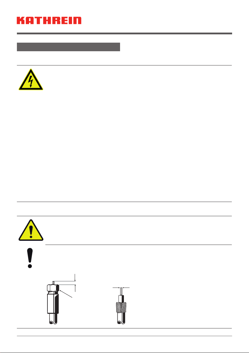
►Das Gerät erst installieren und
benutzen, nachdem Sie dieses Doku-
ment gelesen und verstanden haben.
►Dieses Dokument während der Lebens-
dauer des Geräts aufbewahren. Das
Dokument an nachfolgende Besitzer
und Benutzer weitergeben.
Die aktuelle Version dieses Anwendungs-
hinweises finden Sie auf der Kathrein-Web-
seite www.kathrein.com.
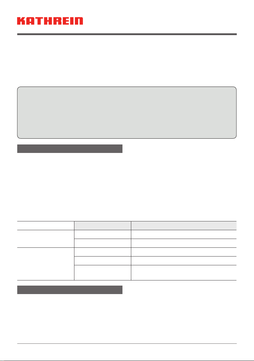
Merkmale
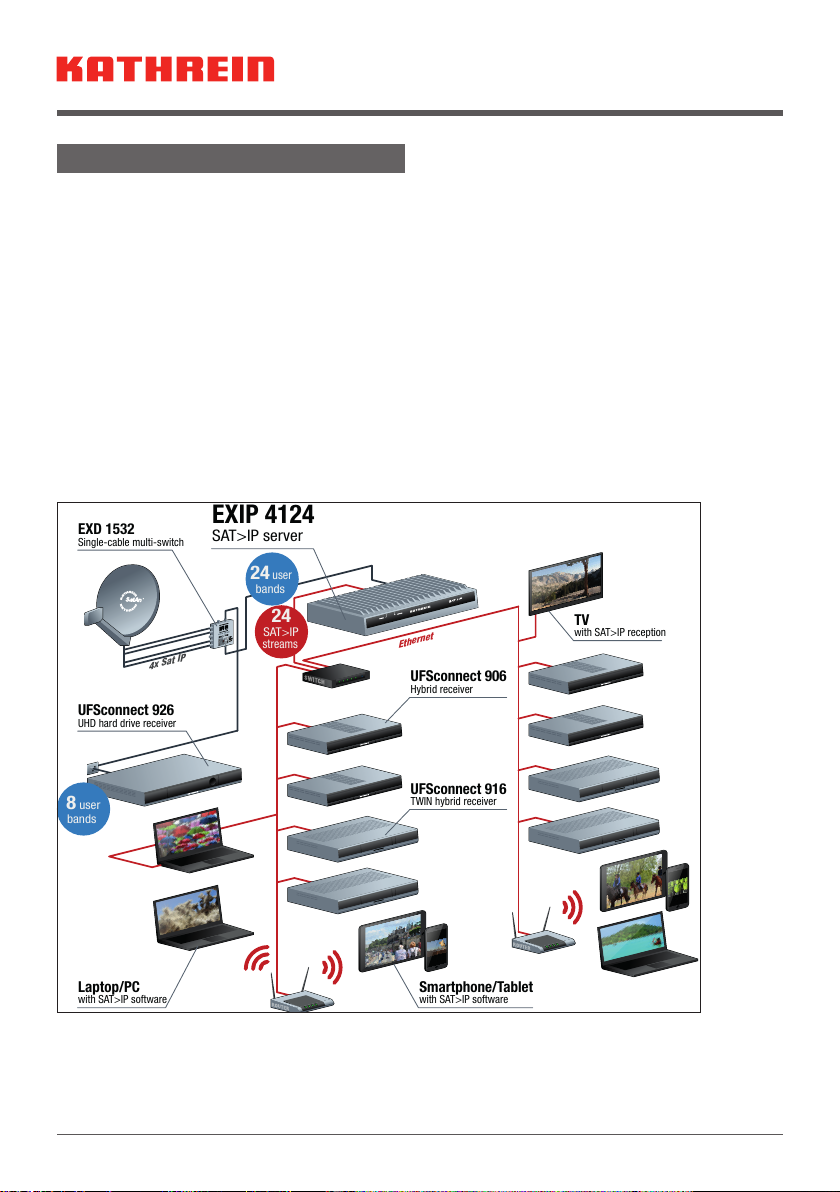
Streamt DVB-S-/S2(HDTV)-Signale von
bis zu 24 Sendern gleichzeitig in einen
IP-Datenstrom
Modernste Fullband-Capture Technolo-
gie für effiziente Datenverarbeitung
Einspeisung in verschiedene Netzwerk-
typen möglich: LAN (auch K-LAN, Pow-
erline), WLAN-Einbindung über Router,
z. B. FRITZ!Box
Unterschiedliche Clients1) möglich:
Tablet PCs, Smartphones, Notebooks,
SAT>IP-fähige Receiver (z.B. UFS906)
Entspricht dem SAT>IP-Standard nach
EN 50585
Betrieb an WideBand LNBs oder
Einkabel-Multischaltern/-LNBs
Unterstützt den Einkabel-Standard nach
EN 50494 und EN 50607
Statusanzeige über LEDs
1) Entsprechende Software/Apps auf dem jeweili-
gen Gerät vorausgesetzt
2)
Entsprechend leistungsfähige Netzwerk-
infrastruktur vorausgesetzt
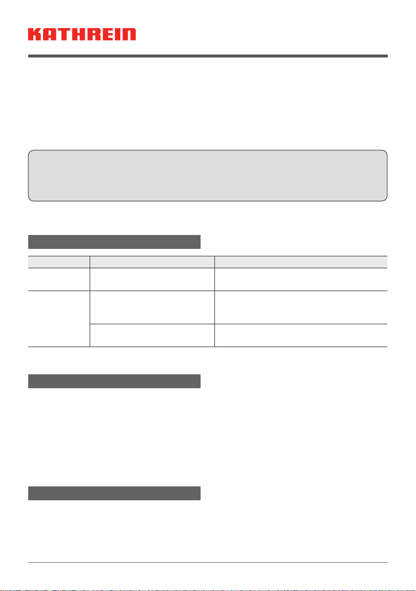
SAT>IP-Server
Abb. 1: EXIP 4124: Vorderansicht
Multicastbetrieb (Static Mode) -> 24 fest
eingestellte Sender für beliebig viele
Teilnehmer
2)
Unicastbetrieb (Dynamic Mode) -> 24 Teil-
nehmer mit jeweils freier Senderwahl
2)
Web-Interface zur Konfiguration, Adminis-
tration und zur Einspielung von Updates
2 Sat-Eingänge mit je 1000mA für die
LNB-Versorgung
Ein Ethernet-RJ45-Anschluss
Ein-/Ausschalter
Für Tischaufstellung oder zur Wandmon-
tage mit beiliegendem Zubehör
Zur Anwendung in Innenräumen
Lieferumfang
EXIP4124
Hocheffizientes Netzteil
Wandhalterungen für das EXIP4124 und
das Netzteil
Kabelschuh für Erdungsanschluss
Gebrauchsanleitung

2 / 8
Bestimmungsgemäßer Gebrauch
Das beschriebene Gerät dient ausschließlich der Installation in Satellitenempfangsanla-
gen.
Jegliche anderweitige Nutzung oder die Nichtbeachtung dieses Anwendungshinweises
hat den Verlust der Gewährleistung oder Garantie zur Folge.
Der Datenstrom, der vom EXIP4124 in Ihr Heimnetzwerk eingespeist wird, kann von nahe-
zu jedem beliebigen IP-fähigen Endgerät wiedergegeben werden. Neben bereits SAT>IP-
fähigen Receivern aus unserem Haus, wie z. B. dem UFS 924, UFS906, UFS916, ist bei
vielen anderen Geräten lediglich das Aufspielen einer SAT>IP-Software notwendig.
Eine Auswahl an Software für PCs, Laptops, Tablets und Smartphones finden Sie auf
unserer Website www.kathrein.de unter der Produktbeschreibung des EXIP4124.
Entnehmen Sie die Verbindung des EXIP4124 mit einem SAT>IP-fähigen Endgerät der
jeweiligen Softwaredokumentation. Normalerweise erfolgt die Verbindung aufgrund der
UPNP-Schnittstelle weitestgehend automatisch.
Abb. 2: Systemgrafik EXIP 4124
*) Pro Kanal werden bis zu 20 MBit/s an Daten übertragen. Achten Sie auf eine entsprechende Leis-
tungsfähigkeit Ihrer Netzwerktechnik!

3 / 8
Montage und Sicherheitshinweise
Sicherheitshinweise
WARNUNG
Lebensgefahr durch elektrische Spannung und sich daraus ergebende Brandge-
fahr!
Unsachgemäße Eingriffe können die elektrische Sicherheit des Gerätes gefährden. Der
Hersteller haftet nicht für Unfälle des Anwenders am geöffneten Gerät. Eigenmächtiges
Öffnen und Reparaturversuche führen zum Verlust des Gewährleistungsanspruchs.
►Nicht öffnen oder am Gerät/Netzgerät manipulieren.
►Bei Arbeiten an der Anlage immer Netzstecker aus der Steckdose ziehen.
►Auf ausreichenden Abstand nach allen Seiten von mind. 5 cm achten.
►Sicherstellen, dass freie Luftzirkulation für die Gerätekühlung möglich ist.
►Auf das Gerät/Netzgerät keine mit Flüssigkeit gefüllten Gegenstände stellen.
►Das Gerät/Netzgerät nicht Tropf- oder Spritzwasser aussetzen.
►Das Gerät/Netzgerät nur bei zulässiger Umgebungstemperatur von 0 bis +40°C
betreiben.
►
Sicherstellen, dass das Netzgerät ohne Schwierigkeiten zugänglich und benutzbar ist.
►Beachten, dass das Gerät/Netzgerät nur durch Ziehen des Netzsteckers vom Netz
getrennt werden kann.
►Das Gerät/Netzgerät nur in trockenen Innenräumen montieren.
►Nicht auf oder an leicht entzündlichen Materialien montieren.
►Sicherstellen, dass das Gerät mit einer Potenzialausgleichsleitung (Cu,
mind.4mm2) versehen ist.
►Die Sicherheitsbestimmungen der jeweils aktuellen Normen EN60728-11 und
EN60065 beachten.
Montagehinweise
►Verbindungsstecker für Koaxialkabel HF-Stecker 75Ω (Serie F) nach EN61169-24
verwenden.
►Nur die mitgelieferte Halterung für das Netzteil verwenden.
►Nicht benutzte F-Anschlüsse mit einem EMK05 spannungsgetrennt abschließen.
ACHTUNG
Gefahr von Sachschäden!
Bei einem größerem Durchmesser des Kabelinnenleiters von mehr als 1,2mm oder bei
einem Grat können die Gerätebuchsen zerstört werden.
Max. 2mm
Überstand
Anzugsmoment
max. 3,4Nm
(Gefahr des
Überdrehens)
Durchmesser
0,6-1,2mm gratfrei

4 / 8
Gerät montieren
Wandmontage
ACHTUNG
Für die Wandmontage nur die beiliegende Halterung verwenden. Beachten Sie, dass
die Schrauben nicht im Lieferumfang enthalten sind.
1. Wandhalterung mit zwei Schrauben
(Ø 4mm, Kopfdurchmesser > 7mm)
montieren.
2. Alle Kabel anstecken und anschrauben.
3. Gerät mit den Füßen von oben in die
Wandhalterung einhängen.
4. In Montagelage Adas Gerät bei nachträglicher Kabelmontage festhalten. Damit wird
verhindert, dass das Gerät aus der Halterung geschoben wird.
Tischaufstellung
Keine Fixierung notwendig
AB

5 / 8
Rückansicht
1 2
8
7
6
543
Abb. 3: EXIP4124: Rückseite
Nr. Funktion
①Stream-LED
②Power-LED
③RF1-Eingang Vim Wideband-Mode; Einkabel-Anschluss nach EN50494 und
EN50607
④RF2-Eingang Him Wideband-Mode
⑤Ethernet-Anschluss (10/100/1000-MBit)
⑥Reset-Taster
⑦Ein-/Ausschalter
⑧Netzteilanschluss (12V/4A)
Gerät anschließen
EXIP4124 an einem Einkabel-Multischalter/Einkabel-LNB anschließen
1. RF1-Anschluss mit einem Einkabel-Multischalter oder Einkabel-LNB verbinden.
2. Gerät mit einem Ethernet-Kabel an den Router anschließen. Im Normalfall vergibt der
Router (z.B. FRITZ!Box) automatisch eine IP-Adresse.
3. Netzteil am EXIP4124 anschließen.
4. Netzteil an die Netzspannung anschließen.
5. Gerät einschalten.
➯Die Power-LED leuchtet. Die Netzwerkverbindung wird hergestellt. Nachdem die
Verbindung hergestellt wurde, leuchtet die blaue Stream-LED.
Standardmäßig ist unter LNB-Einstellung OneCable eingestellt. Ist der EXIP4124 an einem
EN50607 (SCD2)-fähigen Gerät angeschlossen, sind keine weiteren Einstellungen not-
wendig.
Wenn der EXIP4124 an einem Gerät angeschlossen ist, das nur den Standard EN50494
unterstützt:
●Im Web-Interface unter LNB-Einstellungen OneCable einstellen, siehe Web-Interface
bedienen, S. 6.
●Die jeweiligen Userbandfrequenzen eintragen; siehe dazu die Anleitung für das Web
User Interface des EXIP4124.

6 / 8
EXIP4124 an einem Wideband-LNB anschließen
1. RF1 mit V-Ausgang und RF2 mit H-Ausgang des LNBs verbinden.
2. Schritte 2 – 5 ausführen, wie im Abschnitt EXIP4124 an einem Einkabel-Multischalter/
Einkabel-LNB anschließen, S. 5 beschrieben ist.
3. Im Web-Interface Ihres Rechners, Tablets oder Smartphones unter LNB-Einstellungen
Wideband einstellen; siehe Web-Interface bedienen, S. 6.
Tipp Beachten Sie bei Betrieb an einer Einkabelanlage, dass jeder Stream ein
eigenes Userband benötigt und nicht von anderen Geräten belegt werden
darf. Außerdem empfehlen wir Ihnen, den EXIP4124 an einen EXD1532/2532
anzuschließen. Dabei den Modus B 24 + 8 wählen und das Kabel am unteren
Ausgang des Multischalters anschließen – in diesem Fall stehen Ihnen alle 24
Userbänder zur Verfügung.
Gerät bedienen
Gerät ein- und ausschalten
►Ein-/Austaster betätigen, um das Gerät ein- oder auszuschalten.
Gerät auf Werkseinstellungen zurücksetzen
►Reset-Taster ca. 5 Sekunden gedrückt halten.
➯Das Gerät wird auf Werkseinstellungen zurückgesetzt.
LED-Anzeige ablesen
Zustand Bedeutung
Power-LED leuchtet grün Gerät im Betrieb
aus keine Spannungsversorgung
Stream-LED leuchtet blau Netzwerkverbindung ist hergestellt
blinkt blau Aktives Streaming (Datentransfer)
aus Netzwerk nicht angeschlossen oder
Netzwerkverbindung wird hergestellt
Web-Interface bedienen
In den Netzwerk-Grundeinstellungen ist Automatisch eingestellt. D. h., wenn der Server an
einem Router angeschlossen wird, bekommt er automatisch eine IP-Adresse zugewiesen.
Der jeweilige Client (PC, App oder IP-Receiver) erkennt den Server per UPnP und eine
Verbindung kann aufgebaut werden.
Die Satellitengrundeinstellung ist OneCable – EN50607. Jeder RF-Anschluss gibt ein
DiSEqC™- oder Analog-Schaltsignal aus, um das LNB-oder den Multischalteranschluss
auf das benötigte Band zu schalten.

7 / 8
Weitere Einstellungen können im Web-Interface des EXIP 4124 vorgenommen werden.
1. Im Web-Browser die IP-Adresse des EXIP4124 eingeben, gefolgt vom Port 9527,
z.B.192.168.175.35:9527.
2. Passwort exip eingeben.
➯Es ist möglich, die Web-Interface-Einstellungen zu bearbeiten.
Tipp Die IP-Adresse Ihres EXIP4124 finden Sie im Menü Ihres Routers. Alternativ
kann die IP-Adresse mit einem Software-Utility bestimmt werden,
z.B. Intel® Tools for UPnP Technology.
Eine ausführliche Anleitung für das Web-Interface finden Sie unter www.kathrein.de.
Fehlerbehebung
Fehler Mögliche Ursache Fehlerbehebung
Stream-LED
leuchtet nicht
keine Netzwerkverbindung Netzwerkkabel anschließen.
Power-LED
leuchtet nicht
Ein-/Ausschalter steht auf
AUS
Ein-/Ausschalter auf der Rückseite
des Geräts überprüfen und ggf. auf EIN
stellen.
Netzteil nicht angeschlossen Netzteil am Server anstecken und mit
dem 230-V-Netz verbinden.
Reparatur und Austausch
Rep and More GmbH
Hauptstraße 2a
35798 Löhnberg-Oberhausen
Telefon +49 6477 6123 101
Fax +49 6477 6123 020
E-Mail: service-kathrein@repandmore.com
Einen passenden Reparaturbegleitschein finden Sie unter www.kathrein.com ▶Kontakt &
Service ▶ Produktbereich Satellitenempfang.
Transport und Lagerung
►Das Gerät in der Originalverpackung transportieren und lagern.
►Das Gerät vor Staub, Schmutz, Feuchtigkeit und direkter Sonnenstrahlung schützen.
►Das Gerät im zulässigen Temperaturbereich von –25 bis +70 °C transportieren und
lagern. Darauf achten, dass kein Kondenswasser gebildet wird.

KATHREIN-Werke KG, Anton-Kathrein-Straße 1-3, 83022 Rosenheim, Germany, Telefon +49 8031 184-0, Fax +49 8031 184-52360
Techniche Daten
Typ Einheit EXIP4124
Bestell-Nr. 20510136
Frequenzbereich MHz 250 – 2300
Eingang 2 x Sat
Eingangspegelbereich dBµV 42 – 87
Impedanz Ω 75
Fernspeisespannung am
Eingang
V 12 – 20
Fernspeisestrom, max. mA 2x1000
Ausgangsspannung Horizontal V > 17,5 (bei 1 A)/< 19 (bei 0 A)
Ausgangsspannung Vertikal V > 12,5 (bei 1 A)/< 14 (bei 0 A)
Steuersignale Wideband: 14/18 V,
Einkabel-System: EN 50494 und EN 50607
Leistungsaufnahme W typ.12 / min.6
Zulässige Umgebungstempera-
tur im Betrieb
°C 0 – +40
Anschlüsse 2x F-Connector, RJ45, USB,
DC-Buchse 5,5x2,5mm
Abmessungen (B x T x H) mm 222 x 138 x 43
Gewicht kg ca. 0,72
Netzteil
Eingangsnennspannung VAC 100–240 (50–60Hz)
Ausgangsspannung VDC 12
Ausgangsstrom, max. A 4
Erfüllt Richtlinien EN60950-1:2006 + A11:2009 + A1:2010 +
A12:2011 + A2:2013
Entsorgung
Elektronische Geräte
Elektronische Geräte gehören nicht in den Hausmüll, sondern müssen gemäß
Richtlinie 2002/96/EG DES EUROPÄISCHEN PARLAMENTS UND DES RATES
vom 27. Januar 2003 über Elektro- und Elektronik-Altgeräte fachgerecht ent-
sorgt werden. Bitte geben Sie dieses Gerät am Ende seiner Verwendung zur
Entsorgung an den dafür vorgesehenen öffentlichen Sammelstellen ab.

1 / 8
EXIP 4124 20510136
About This Guide
This document is part of the product.
►Do not install or use the device until
you have read and understood this
document.
►Keep this document for reference
throughout the service life of the device.
Pass this document on to any new
owner or user.
For the most up-to-date version of this
document, go to the Kathrein website
www.kathrein.com.
Characteristics
Streams DVB-S/S2 (HDTV) signals from
up to 24 channels simultaneously in an
IP data stream
Cutting-edge Full-Band Capture tech-
nology for efficient data processing
Can be fed into different network types:
LAN (also K-LAN, Powerline), WLAN
integration via router, e.g. FRITZ!Box
Can be configured for different clients1):
tablet PCs, smartphones, notebooks,
SAT>IP-capable receivers (e.g. UFS 906)
Conforms to the SAT>IP standard
according to EN 50585
Operation at wideband LNBs or
single-cable multi-switches/LNBs
Supports the single-cable standard
according to EN 50494 and EN 50607
Status display via LEDs
1) Provided the required software/apps are
installed on the device
2)
Provided a powerful enough network
infrastructure is available
Sat>IP Server
Fig. 1: EXIP 4124: Front view
Multicast operation (static mode) ->
24 preset channels for any number of
subscriber
2)
Unicast operation (dynamic mode) ->
24 subscribers with free choice of chan-
nels each
2)
Web interface for configuration, adminis-
tration and import of updates
2 Sat inputs with 1000mA each for LNB
supply
1 Ethernet RJ45 connection
On/Off switch
Can be set up on a table or mounted on
a wall using the included fittings
For indoor use
Scope of Delivery
EXIP 4124
Highly-efficient power supply unit
Wall brackets for mounting the EXIP4124
and the PSU on a wall
Cable shoe for earthing connection
Instructions for use

2 / 8
Intended Use
The device described is intended solely for the installation in satellite receiver systems.
Any other use, or failure to comply with these instructions will invalidate the warranty or
guarantee.
The data stream that is fed by the EXIP 4124 into your home network can be played by
virtually every IP-capable end device. Kathrein receivers such as the UFS 924, UFS906,
UFS916 are already SAT>IP-capable, many other devices only require the installation of a
SAT>IP software.
A choice of software for PCs, laptops, tablets and smartphones is available on our web-
site www.kathrein.de, on the EXIP4124 product page.
The connection of the EXIP 4124 to a SAT>IP-capable end device is indicated in the cor-
responding software documentation. Due to the UPNP interface, the connection is usually
carried out mostly automatically.
4x Sat IP
UFSconnect 926
UHD hard drive receiver
UFSconnect 916
TWIN hybrid receiver
Ethernet
24
streams
SAT>IP
24
user
bands
8
user
bands
EXD 1532
Single-cable multi-switch
EXIP 4124
SAT>IP server
UFSconnect 906
Hybrid receiver
Smartphone/Tablet
with SAT>IP software
Laptop/PC
with SAT>IP software
TV
with SAT>IP reception
Fig. 2: System chart EXIP 4124
*) Up to 20 MBit/s of data are transmitted per channel. Make sure that your network infrastructure has
sufficient capacity!

3 / 8
Installation and Safety Instructions
Safety Instructions
WARNING
Danger to life from electric shock and fire hazard due to electric current!
Tampering with the unit may jeopardise its electrical safety. The manufacturer accepts
no liability for accidents caused by the user opening the unit. Opening the unit and
attempting to repair it yourself voids all warranty claims.
►Do not open the device/power supply unit or tamper with it.
►When working on the system, always unplug the mains plug from the wall socket.
►Ensure adequate clearance. Clearance all round must be at least 5 cm.
►Risk of overheating! Make sure there is free circulation of air to dissipate the heat
from the unit.
►Do not place any liquid-filled items on top of the device/power supply unit.
►Do not expose the device/power supply unit to dripping or splashing water.
►Operate the device/power supply unit in the permissible ambient temperature
range of 0 to +40° C only.
►Ensure that the power supply unit is easily accessible and usable.
►Pull the plug out of the mains socket to completely disconnect the device/power
supply unit from the mains.
►Install the device/power supply unit in dry indoor areas only.
►Do not install on or against highly combustible materials.
►Make sure that the device is equipped with an equipotential bonding conductor
(Cu, at least4mm2).
►Make sure to comply with the safety regulations set out in the current EN 60728-
11 and EN 60065 standards.
Installation Instructions
►Connectors for coaxial cables: RF connectors 75Ω (series F) according to
EN61169-24.
►Only use the supplied bracket for the power supply unit.
►Terminate unused F-type connectors with an EMK05 (voltage-separated).
NOTICE
Risk of damage to property!
An inner cable conductor with a diameter greater than 1.2mm, or the presence of
burrs may damage the device inputs/outputs beyond repair.
Max. 2mm
excess
length
Clamping torque
3.4Nm max.
(danger of over-
winding)
Diameter
0.6-1.2mm free of burrs

4 / 8
Installing the Device
Wall Mounting
NOTICE
For wall mounting, only use the supplied bracket. Screws are not included in the
scope of delivery.
1. Mount the wall support with two screws
(Ø 4mm, head diameter > 7mm)
2. Attach/screw on all cables.
3. Insert the device from above with feet
into the wall support.
4. In the mounting position A, hold the device during the subsequent cable installation
work, thus preventing the device from being pushed out of the support.
Table Mounting
No fastening required
AB

5 / 8
Rear View
1 2
8
7
6
543
Fig. 3: EXIP4124: Back panel
No. Function
①Stream LED
②Power LED
③RF1 input Vin wideband mode; single-cable connection (EN50494 and EN50607)
④RF2 input Hin wideband mode
⑤10/100/1000-MBit Ethernet connection
⑥Reset button
⑦On/Off switch
⑧Power supply connection (12V/4A)
Connecting the Device
Connecting the EXIP4124 to a Single-cable Multi-switch/Single-cable LNB
1. Connect RF1 input to a single-cable multi-switch or single-cable LNB.
2. Connect the device to a router with an Ethernet cable. Normally, the existing router
(e.g. FRITZ!Box) will automatically assign an IP address.
3. Connect the power supply unit to the EXIP4124.
4. Connect the power supply unit to the mains voltage.
5. Switch on the device.
➯The Power LED lights up. Connection to the network is being established. When
the network is connected, the blue Stream LED lights up.
The default setting for LNB Settings is OneCable. If the EXIP4124 is connected to an
EN50607 (SCD2)-capable device, no further settings are required.
If the EXIP4124 is connected to a device that only supports the EN50494 standard:
●Select OneCable under LNB Settings
in the web interface, see
Operating the Web Inter-
face, p.6.
●Enter the corresponding user band frequencies, see Instructions for the Web User
Interface for the EXIP 4124.

6 / 8
Connecting the EXIP4124 to a Wideband LNB
1. Connect RF1 to the V-output and RF2 to the H-output of the LNB.
2. Carry out steps 2 – 5 as described in the paragraph Connecting the EXIP4124 to a
Single-cable Multi-switch/Single-cable LNB, p.5.
3. Select Wideband under LNB Settings in the web interface of your PC, tablet or smart-
phone; see Operating the Web Interface, p.6.
Tip Please note that when operated in a single-cable system, each stream
requires its own user band and must not be used by other devices. We also
recommend to connect the EXIP4124 to an EXD1532/2532. Select the
B24+8 mode and connect the cable to the lower output of the multi-switch
– in this case all 24 user bands will be available.
Operating the Device
Turning the Device on and off
►Use the On/Off switch to turn the device on or off.
Resetting the Device to Factory Settings
►Keep the reset button pressed for approx. 5 seconds.
➯The device is restored to factory settings.
Reading the LED Display
Status Definition
Power LED Lights up green Device is in operation
Off No voltage supply
Stream LED Lights up blue Network connection is established
Flashes blue Active streaming (data transfer)
Off Network is not connected or is still con-
necting
Operating the Web Interface
The network basic settings are Automatic. This means that when the server is connected to
a router, it is automatically allocated an IP address.
The respective client (PC, app or IP receiver) detects the server via UPnP and a connec-
tion can then be established.
The satellite basic setting is OneCable – EN50607. Each RF port emits a DiSEqC™- or
analogue switch signal to switch the respective LNB or the multi-switch connection to the
required band.
Additional settings can be made in the EXIP4124 web interface .

7 / 8
1. Enter the IP address of the EXIP4124 in the web browser, followed by the port 9527,
e.g. 192.168.175.35:9527.
2. Enter the password exip.
➯It is possible to edit the web interface settings.
Tip The IP address of your EXIP4124 is indicated in the router menu. Alternative-
ly, the IP address can be determined using a software utility,
e.g. Intel® Tools for UPnP Technology.
You will find more detailed instructions for the web interface at www.kathrein.com.
Troubleshooting
Problem Possible cause Solution
Stream LED
does not
light up
No network connection Connect network cable
Power LED
does not
light up
ON/OFF switch is positioned
on OFF
Check the switch on the rear panel of the
device and set it to ON
Power supply unit is not
connected
Connect the power supply unit to the
server and connect it to the 230-V mains.
Repair and Replacement
Rep and More GmbH
Hauptstraße 2a
35798 Löhnberg-Oberhausen, Germany
Phone +49 6477 6123 101
Fax +49 6477 6123 020
E-Mail: service-kathrein@repandmore.com
A repair form can be downloaded at www.kathrein.com ▶Contact & Service ▶ Satellite
Reception.
Transport and Storage
►Transport and store the device in its original packaging.
►Protect the device against dust, dirt, moisture and direct sunlight.
►Transport and store the device only in the permitted temperature range between -25
and +70°C. Make sure there is no water condensation build-up.

KATHREIN-Werke KG, Anton-Kathrein-Straße 1-3, 83022 Rosenheim, Germany, Phone +49 8031 184-0, Fax +49 8031 184-52360
Technical Data
Type Unit EXIP 4124
Order no. 20510136
Frequency range MHz 250 – 2300
Input 2 x Sat
Input level range dBµV 42 – 87
Impedance Ω 75
Remote feed voltage input V 12 – 20
Max. remote feed current mA 2x1000
Output voltage, horizontal V > 17.5 (at 1 A)/< 19 (at 0 A)
Output voltage, vertical V > 12.5 (at 1 A)/< 14 (at 0 A)
Control signals Wideband: 14/18 V,
Single-cable system: EN 50494 and EN 50607
Power consumption W typ.12 / min.6
Permissible ambient tempera-
ture (in operation)
°C 0 – +40
Connections 2x F-type connectors, RJ45, USB,
DC jack plug 5.5x2.5mm
Dimensions (W x D x H) mm 222 x 138 x 43
Weight kg approx. 0.72
Power supply unit
Nominal input voltage VAC 100–240 (50–60Hz)
Output voltage VDC 12
Max. output current A 4
Fulfils the directives EN60950-1:2006 + A11:2009 + A1:2010 +
A12:2011 + A2:2013
Disposal
Electronic equipment
Electronic equipment is not domestic waste – in accordance with directive
2002/96/EC OF THE EUROPEAN PARLIAMENT AND THE COUNCIL dated
27th January 2003 concerning used electrical and electronic appliances, it
must be disposed of properly. At the end of its service life, take this unit for
disposal at a designated public collection point.
Other manuals for EXIP 4124
1
This manual suits for next models
1
Table of contents
Languages:
Other Kathrein Server manuals
Popular Server manuals by other brands

Polycom
Polycom RealPresence RMX 1800 Installation & quick start guide

Intergraph
Intergraph InterServe 05 Setup Setup manual

HP
HP T5135 - Compaq Thin Client Quickspecs

IBM
IBM System x3100 M4 Installation and user guide

HP
HP ProLiant DL360p installation instructions

Dell
Dell XC730xd Getting Started With Your System