2
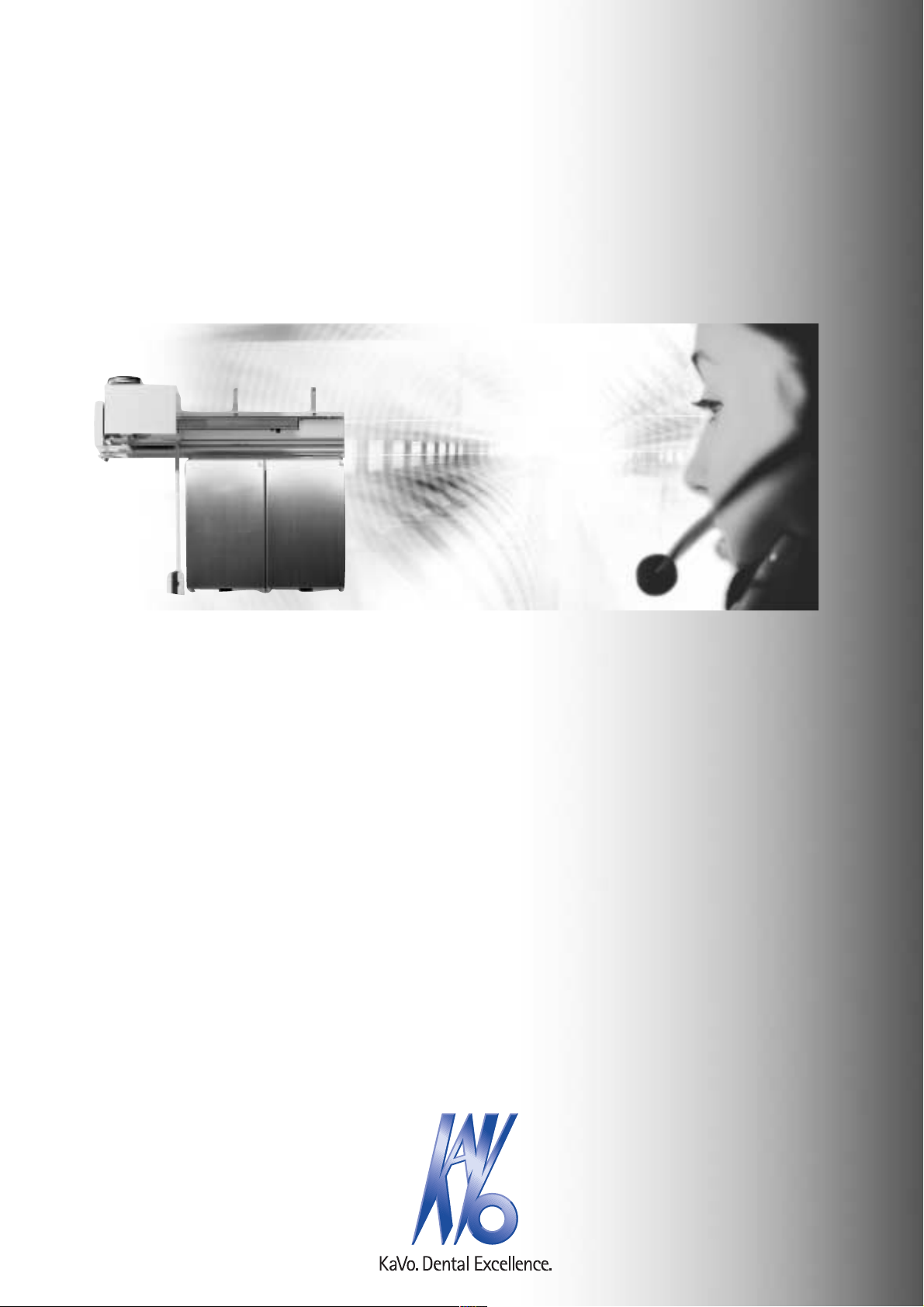
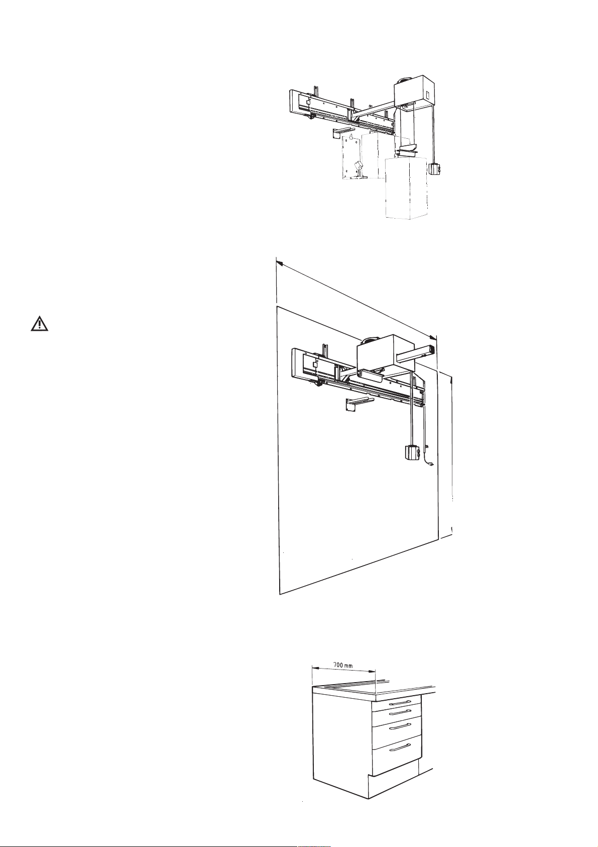
Electric Dispenser Hoist EWL 2, 3, 4
A 1.2 Important information
The instructions for use should be
read by the user before starting up the
unit for the first time, in order to avoid
incorrect operation and other damage. If
other language versions are required, please
request these from your responsible KaVo
agent. Duplication and distribution of the
instructions for use (IU require KaVo's
prior consent.
All technical data, information and proper-
ties of the product described in the IU cor-
respond to the state on going to press.
Modifications and improvements to the
product as a result of new technical devel-
opments are possible.
This does not imply any right to retrofitting
of existing units.
KaVo assumes no responsibility for damage
arising through:
• external influences (poor quality of the
media or inadequate installation
• use of incorrect information
• improper use
• improperly performed repairs.
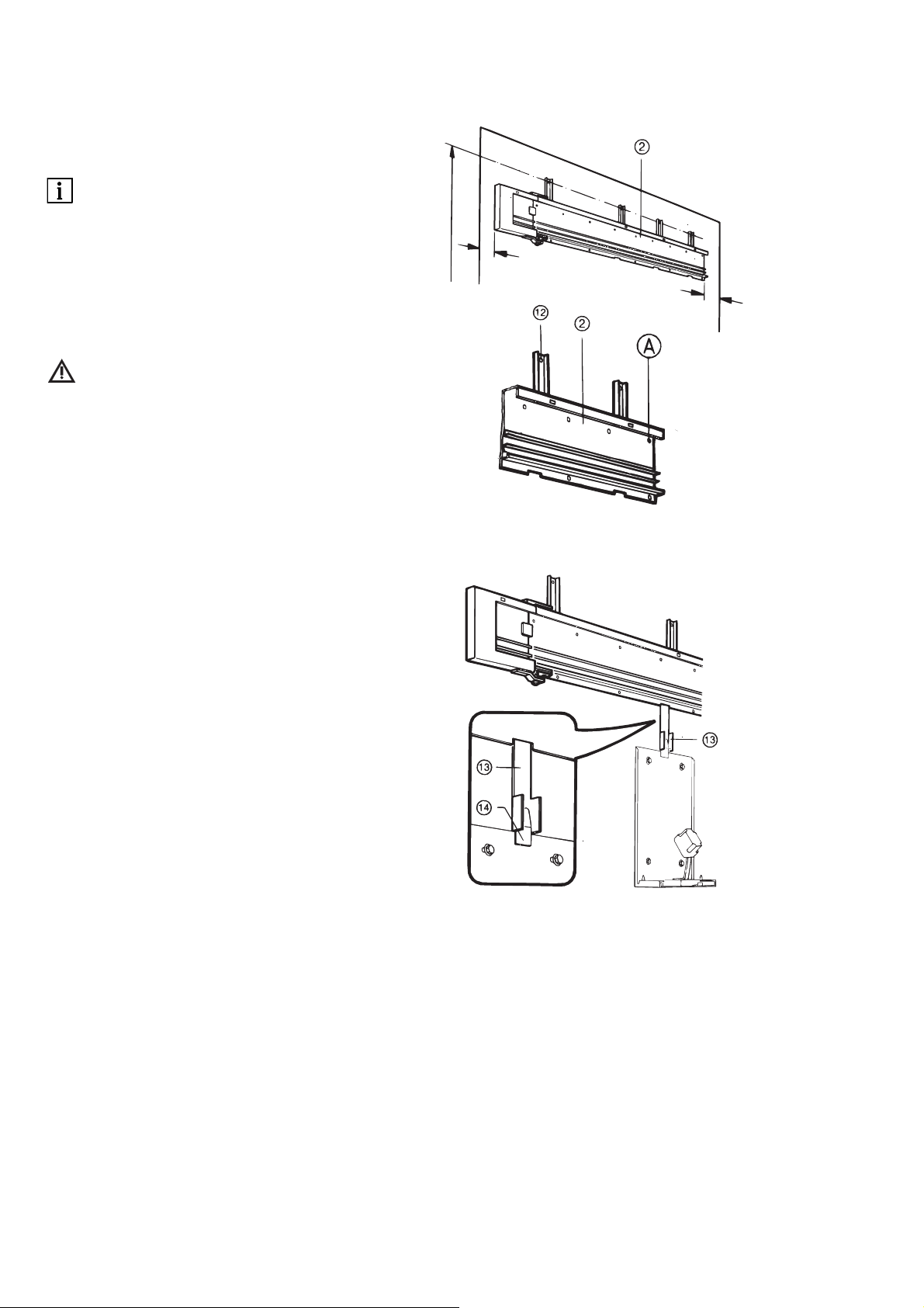
Repair and maintenance work - apart from
the activities described in these instructions
for use - may be performed only by quali-
fied technical personnel.
In the event of modifications by third par-
ties, the approvals become null and void.
KaVo recommends using only original
spare parts for operation and for repair.
A 1.3 Precautions
Safe operation and protection of the unit
are ensured only through proper use in
accordance with the instructions for use and
using the tools approved for the purpose.
The following should also be observed:
• the work safety regulations,
• the accident prevention regulations.
In accordance with these conditions it is the
duty of the user:
• to use only flawless working materials,
• to observe correct usage and applications,
• at no time to exceed the maximum
carrying capacity,
• to ensure that nobody finds themselves
under the hoist or the mobile carrier when
in operation,
If the unit is not in operational condition as
prescribed by regulations, or improperly
used , for example:
• for the transportation of inappropriate
loads,
this can lead to the following consequences:
• loosening of wall fixtures
• breakage of the steel rope
• damage to the hoist arm, the guide rollers,
the motor or the drive movement.
• Safety features must not be bridged or
bypassed.
• Danger notices on the product are to be
observed.
• Other mechanical dangers are not to be
ruled out.
• Silolift to be operated by only one person.
A 1 User information
A 1.1 Meaning of the pictograms
Situations where failure to follow the
instructions may lead to danger,
damage to material or operating faults.
Important information for operator
and engineer.
Automatic mode
Automatic sequence
Close, screw in,
fasten, etc.
Open, release, loosen
+ more, higher
- less, lower
• Continuous operation
Time, time sequence
Disconnect mains plug