VENCO VC-416 ES Operating instructions


6245
-
6-13-00C
8-18-00D
TABLE OF CONTENTS
VP / VC - 6D SUPERCEDES
TITLE DATE SECTION
TABLE OF CONTENTS
VP / VC - 6D MANUAL
PAGE DESCRIPTION REF.NO.
1 GENERALINFORMATION ...................................................... 6246
2 PREPARATION-MOUNTINGHOIST ........................................ 6241
3 UPPERNEST& REARHINGES .............................................. 6248
4 HOISTFRAMEONCHASSIS .................................................. 6242
5 LONGITUDINALSUPPORTS-OPTION .................................... 6244
6 HYDRAULICS ......................................................................... 6122
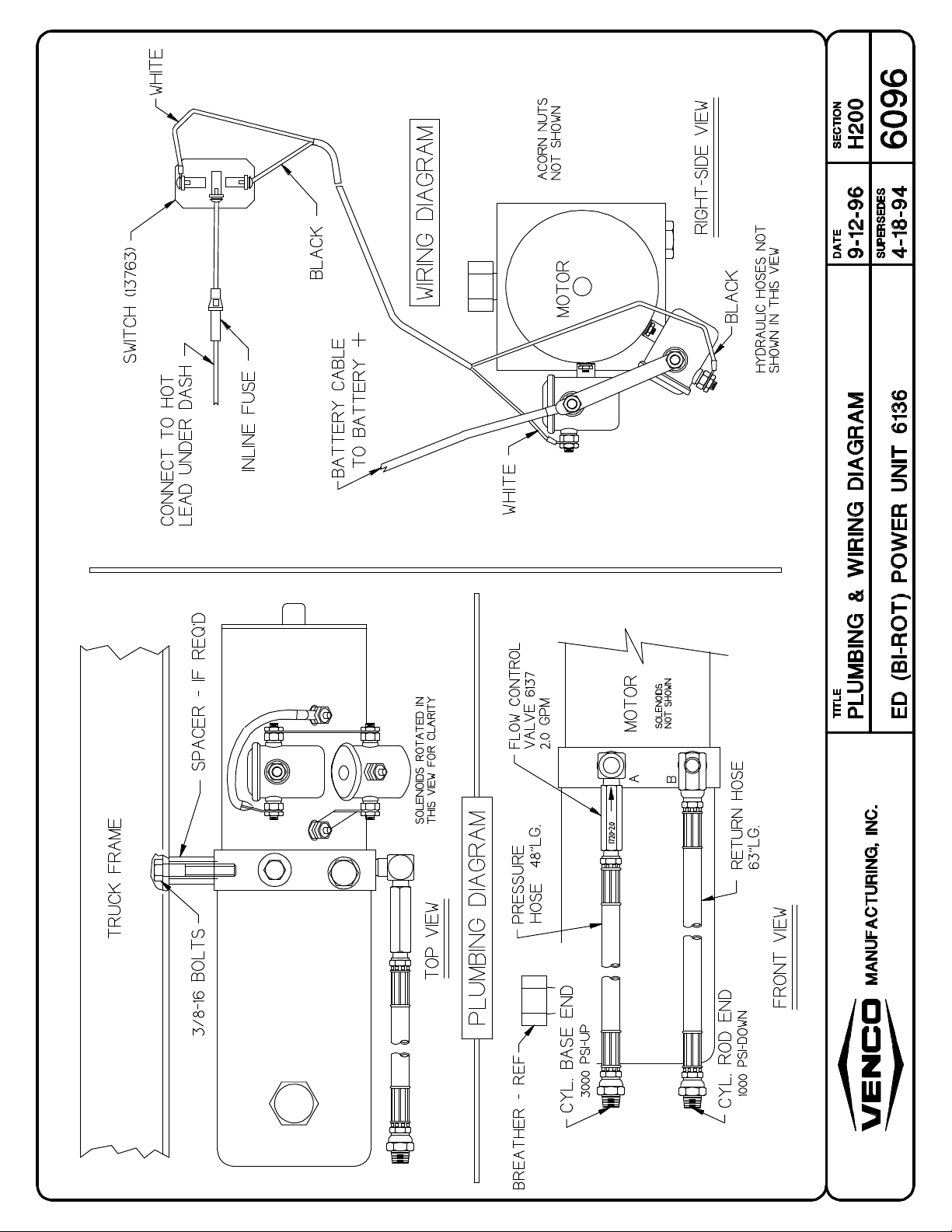
7 EDHOISTPOWERUNIT(BI-ROT) ........................................... 6096
8 6425 ED POWER UNIT PLUMBING & WIRING ......................... 6493
9 6425EDPOWERUNITW/PUSHBUTTONINSTALLATION........ 6500
10 6426 ES POWER UNIT ............................................................ 6506
11 6426 ES POWER UNIT W/ PUSH BUTTON CONTOL ................. 6507
12 RESERVOIRFILLING ............................................................. 416140
13 ESHOISTPOWERUNIT ......................................................... 6133B
14 DASH CONTROL SWITCH ....................................................... 6123
15 DASHCONTROLDRAWING ................................................... 40124
16 UPPERNEST PIVOTS- BODY ............................................... 6243
17 UPPERNEST PIVOTS-UPPER NEST .................................... 6251
18 FUELFILLERTUBE-SUPPORT ............................................. 6252
19 BUMPERBRACKETS ............................................................ 6072
20 LUBRICATION/SERVICECHART ........................................... 40260
21 BUMPER,GREASEFITTINGS,DECALS ................................. 6118
22 CONTRACTORREARHINGE&UPPERPIVOTS ..................... 6250
23 HOISTREPLACEMENTPARTSDRAWING .............................. 6255
24 HOISTREPLACEMENTPARTSLIST ....................................... 6256
25 FENNERESPARTSLIST ....................................................... 40058-2
26 MTEED(BI-ROT)6136POWERUNIT .................................... 6097
27 REPLACEMENT PARTS DWG - ED POWER UNIT .................... 6486
28 REPLACEMENT PARTS LIST - ED POWER UNIT .................... 6487
29 REPLACEMENT PARTS DRAWING ES POWER UNIT .............. 6508
30 REPLACEMENT PARTS LIST ES POWER UNIT ....................... 6509
31 WARRANTYPAGE ................................................................ 12-00073
-PDECALSANDPACKAGEINCLUDES:
12524 CAUTIONSTANDCLEAR 2 PCS.
416052 CAUTIONDECAL 2 PCS.
6066 PLASTICBAG 1 PC.
12-00075 ENVELOPE 1 PC.
MANUFACTURING,INC.
BOOKMARKS
THUMBNAILS

VP/VC-6D HOIST SPECIFICATIONS OVERVIEW
VP - PICK-UP PowerSource:
VC-CONTRACTOR ES - Electric Single Acting
6-*6000lbs.CAPACITY ED - Electric Double Acting
Designed for: '94 - Current Dodge 1/2 & 3/4 ton pickup trucks and club cabs
NOTE: Foroptional longitudinal body supports-add30lbs.
Recommended if payload is in excess of 1000 lbs.
1/2ton&some3/4tontrucksmayrequireoverload/helperspringstokeephoistfrombeing
toolow.
Suggestedmaximum capacityforpick-up bed
Specifications:
Weight - 265 lbs (ES/ED)
Cylinder - 3-1/2" dia, 12-7/8" stroke
Operating Pressure - 2400 psi "up" (ES/ED) and 650 psi "down" (ED only)
12-VoltElectricHydraulicSingleActingPump(Option-DoubleActingPump)
Factoryassembledscissorswithbasemountingfasteningtochassisframecrossmember-bolt
on& no welding. Welding onlyrequiredonUpperNest Pivot Assemblies.
IMPORTANT: Toavoidcostlydelaysininstallationandimproperoperation,readandunderstandthis
manualinitsentiretybeforeproceeding.
WARNING: Wheneverworkormaintenanceisperformedonatruckunderaraisedbody,always
remembertopropthebodyupwiththeoptionalsafetyprop(40042)oranothersafe
methodtoavoidinjuryfromthebodyinadvertentlyfalling.
6246
H200
7-6-98A
1-19-99B
SPECIFICATIONS
VP/VC-6D SUPERCEDES
TITLE DATE SECTION
HTGNELACGNAHREVO°04TAYTICAPAC
'7"65"0snot34.3
'8"65"01snot97.3
'9"65"22snot05.4
•Cab to axle dimensions may differ
resulting in a change in capacities
shown.
•Capacities include weight of body
which must be deducted to
determinepayload.
Caution - Weight of chassis
combinedwithweightofbody,hoist
andpayloadcannotexceedGVWR
orGAWRoftruck.
PLATFORM AND DUMP APPLICATIONS
*
MANUFACTURING,INC.

6241
H200
10-24-94
7-6-98A
INST INSTRUCTIONS
VP/VC-6D SUPERCEDES
TITLE DATE SECTION
VP-6D DODGE PICKUP HOIST INSTALLATION INSTRUCTIONS
1. Removepick-upbumperandpickupbodyandremovesparetirewinchextensionatrightof
licenseplate bracket. Keeptheextension and brackettobe reinstalledlater. Disconnect
taillightsoranyotherelectricalitemsattachedtothebed(pickupbody). Savethebedbolts.
2B. Afterremovingthepickupbody,cutthetaperedpartattherearofthechassisframeasshown
inFIGURE2B.
2C. See FIGURE 2C. Cut 4-5/8 inches off the driver side (left side) of the Hoist Frame Upper
PivotShaft (1-1/2" dia. x21" - ref.)
3. RearHinge:
6248 - SeeFigure3A. Fastenthelowerrearhingetotherearofthetruckframerailcut-out
in step 2B with the 1/2"-13 x 1" bolts, nuts and lock washers (3 each required per
lowerrearhinge). Iftheholesinthelowerrearhingedon'talignwiththeholesinthe
framematchdrilltheholesusingthelowerrearhingeasaguide. Fastentheupper
rearhinge(withthecollarstowardinside)totherearbedcrossmembersusingthe
bed bolts - see Figure 3B.
4. UpperNest:
6248 - See Figure 4. Offset theUpperNest2-1/2"towardtherightside(curb side). Use
5/16"-18x 3" bolts to fastenthe Upper Nest tothe under side of thepickup bed.
MANUFACTURING,INC.

TITLE SECTION
SUPERCEDES
DATE
6248
H200
1-31-95
7-6-98AINSTALLATION DRAWING
VP/VC-6D
MANUFACTURING,INC.

6242
H200
10-24-94
7-6-98A
INST INSTRUCTIONS
VP/VC-6D SUPERCEDES
TITLE DATE SECTION
5&6.LongitudinalSupports (optional)&Plastic Pads:
- See instructions on page 6244
7. HoistMainframe:
TheHoistMainframeisoffset2-1/2inchestowardthecurbside(rightside). Put3/8"-16x3"
bolts with flat washer up through the inside of the chassis frame rails on each side of the
crossmemberandupthroughthe2inchsquaretube-7/16"holethrougheachendoftubeand
put3/8"lockwasherandhexnutonthetopsideofthetube. Usethe4holesinthe1/4"thick
Base Plate as a guide to drill four 5/16" dia. holes through the front flange of the chassis
crossmember- seeFIGURE7Dbelow.
8. Hydraulics:
Powerunitcanbe mounted under the hood at the auxiliary batterylocation-rightside, but
longerhosesarerequiredone13FT.andone14FT. Otherwise,mountPowerUnitsameas
specified in the instructions - See instructions on pages 6122, 6096, and 6133B.
9. Electrical:
Connectthebatterycabletothepositiveleadinthefuseboxnexttothebatteryunderthehood.
10. DashControlSwitch:
- See instructions on page 6123
MANUFACTURING,INC.

TITLE SECTION
SUPERCEDES
DATE
6244
H200
1-30-95
7-6-98INSTALLATION DRAWING
VP/VC-6D
MANUFACTURING,INC.

6122
H200
11-6-95
7-6-98
INST INSTRUCTIONS
VP/VC-6D, VP/VC-6R SUPERCEDES
TITLE DATE SECTION
8. InstallingHydraulics:
Important- Besuretoblowdirtandothermaterialoutofthehose(s)withcompressedair
topreventthehydraulicsystemfrombeingcontaminated.
A. ED(Electric Double Acting) Power Unit:See Dwg. 6096 (Bi-rotationalpower unit)
1. Installtheshorthydraulichosetothefull/baseendofthecylinder. Connectthelong
hydraulichosetotherodendofthecylinder. Directhosestotherightoftheframe.
2. Install the ED (Electric Double Acting) Power Unit (6136 Bi-Rotational) on the
outsideoftheframejustforwardoftherightrearfrontspringhanger. Put1/2"pipe
spacers1-1/4"longbetweenframeandpowerunit,ifrequired. Boltthroughframe
andpipeintosideofpowerunit-use3/8"-16bolts,3/8"washersandlockwashers
(2 each required). Be sure not to drill through cables running on inside of truck
longsills. Connecttheshort(pressure)hoseandlong(return)hoseasshownon
Dwg. 6096.
B. ES (Electric Single Acting) Power Unit: See Dwg. 6133B
Installbreather#40226intorod-endportofcylinder. Installhosetothefull/baseend
ofcylinder. Mountpowerunittotruckframewith3/8"-16bolts,3/8"lockwashersand
washersoninsideoftruckframetopreventinterferencewithsideoftruckbed.
NOTE: Be sure hoses are not crimped and use cable ties to secure hoses in a safe
mannerbetweencylinderandpowerunit.
NOTE: Checkhydraulicfluidlevelinpowerunitreservoir. Iffluidisrequired,useDextron
II- ATF,mobileDTE 13 orequivilent. Fill3/4" fromthetop of thereservoir.
MANUFACTURING,INC.


6493
-
2-8-00
10-27-00A
6425 ED POWER UNIT
VP6S SUPERCEDES
TITLE DATE SECTION
MANUFACTURING,INC.
6425 ED (DOUBLE ACTING)
POWER UNIT

6500
-
10-27-00A
8-24-01B
6425 ED POWER UNIT
VP6S SUPERCEDES
TITLE DATE SECTION
MANUFACTURING,INC.
6425 ED WITH MONARCH PUSH BUTTON CONTROL
416533 MONARCH PUSH
BUTTON CONTROL
NOTE: ENERGIZING 'G' COIL SENDS FLOW TO 'C1' PORT (HOIST UP)
ENERGIZING 'R' COIL SENDS FLOW TO 'C2' PORT (HOIST DOWN)
BLKWHT
RED GRN
C2PORT

6506
-
6-9-00A
8-2-01B
6426 ES POWER UNIT
VP6S SUPERCEDES
TITLE DATE SECTION
MANUFACTURING,INC.
6426 ES (SINGLE ACTING) POWER UNIT
NOTE: ENERGIZING'B'COIL RELEASES 'C1' PORT
ENERGIZING SOLENOID COIL SENDS FLOW TO 'C1' PORT
B
WGTO BAT.
POST 416527
WIRINGHARNESS
SWITCH
BREATHER
PLUG
B
W

6507
-
5-30-00
6-9-00A6426 ES PWR UNIT W/ PUSHBUTTON INST.
VP6S
MANUFACTURING, INC.
6426 ES (SINGLE ACTING) POWER UNIT
NOTE: ENERGIZING 'B' COIL RELEASES 'C1' PORT
ENERGIZING SOLENOID COIL SENDS FLOW TO 'C1' PORT
B
WGTO BAT.
POST
BREATHER
PLUG
6501 MONARCH PUSH
BUTTON CONTROL

TITLE SECTION
SUPERCEDES
DATE
416140
H300
2-1-94
9-15-97
FILLING HYD. RESERV.
VP/VC6(R) - VC520
INSTRUCTIONS FOR FILLING THE RESERVOIR OF
ELECTRIC HYDRAULIC POWER UNITS
THEFOLLOWINGHOISTMODELSAREINCLUDED:
VP/VC-6(R), VC-416/516, VC-520 - ES & ED
PROCEDURE
STEP 1 - On 416, 516, 520 ES models only, do not attach rod
end hose to the cylinder until after completing Steps 2
thru 6.
STEP 2 - Removethe reservoirbreather. Withthe hoistinthe
downposition,fillthereservoirwithATF-DextronII
(MobileDTE 13or equivalent)- 3.5qts. for416, 516,
520 and 2 qts. for VP-6(R).
STEP3- Raisethehoisthalfway(22-25°dumpangle,
approx. 8" of cylinder stroke).
STEP 4 - Fillthe reservoirwith anadditional 2qts.for VP-6(R),
416, 516 and 3 qts. for 520.
STEP 5 - Raise the hoist completely.
STEP 6 - Refillthereservoirwiththeremainingfluidrequired.
STEP 7 - Attach hose to rod end of cylinder on the 416, 516,
520 ES models.
MODELNO. RESERVOIRCAPACITY TOTAL
FLUIDREQ'D
VP/VC-6(R)ED 2QTS. 3.5QTS
VC-416ES/ED 4QTS. 5.5QTS
VC-516ES/ED 4QTS. 7.5QTS
VC-520ES/ED 4QTS. 9.0QTS.
Example: VC-416ES/EDHoist
Step 2 - Add 3.5 qts.
Step 3 - Add 2.0 qts.
Step 4 - Add0.0qts(nonereq'd)
= 5.5 qts. total
MANUFACTURING,INC.


6123
H200
7-7-98A
1-16-02B
INST INSTRUCTIONS
VP/VC-6D, VP/VC-6R SUPERCEDES
TITLE DATE SECTION
10. DashControlSwitchInstallation: SeeDwg.40124
- Installdashmountingplateunderthedashinaconvenientlocationforoperatorcontrol.
Usethe#12panheadslottedscrews, 1/2"long, furnishedin kit.
- Installswitchextensionontotoggleswitch.
- Connectcenterpostofswitchtothe20ampin-linefuse.
Connectfusetohotleadunderdash.
- Connectthe16/2SJOcableinthefollowingmanner:
Connectonewireleadtotoppole,andtheotherleadtothelowerpoleofswitch. Runcable
tothepowerunit.
Single Acting: See Dwg. 6133B, 6506, 6507.
Double Acting: See Dwg. 6096, 6493, 6500.
MANUFACTURING,INC.

40124
H200
1-22-90A
5-15-98B
DASH CONTROL INSTALLATION
VP/VC-6 SERIES SUPERCEDES
TITLE DATE SECTION
MANUFACTURING,INC.

6243
H200
7-7-98
2-22-01A
INST INSTRUCTIONS
VP/VC-6D SUPERCEDES
TITLE DATE SECTION
11. UpperNestPivotAssemblies:
BesuretheshortUpperPivotAssemblyisontheleftsideandnothittingtheFuelTank.
BesurethattheverticalflangeontheUpperPivotAssemblyistowardthecab. SeeFigure
7D on page 6242 and Figure 11 below.
12. InstallingBodyonTruck:
BesurethePowerUnitandHoistareoperatingproperly. CycletheHoistupanddown
2-3timesbeforeinstallingthebodyonthetruckframe-chassis. Placethebodybackon
thepickupchassisandinstalltherearhingepivotpins(1"dia.x5-1/16"-2required). The
headonthe hingepinshouldbeontheoutsideofthehinge. Usea 1/4"x1-3/4"rollpin
throughthecollarontheinsideofthehingeandthroughtheholeinthehingepinonboth
hinges. Loosenthebedboltsontherearhingetopositionthebodysquare(lefttoright)
with the truck cab. Tighten all the fasteners on the rear hinges (left and right) before
continuing.
MANUFACTURING,INC.

6251
H200
7-7-98A
10-1-99B
INST INSTRUCTIONS
VP/VC-6D SUPERCEDES
TITLE DATE SECTION
13A.Attaching Upper Nest Pivots to Upper Nest: See Figure 13A
BesuretheflangesontheUpperPivotarepositionedasspecifiedinStep11,withthe
vertical flange toward the cab. Power the hoist upward so the Upper Pivots make
contactwiththeUpperNest. Theknuckleofthehoistscissorsshouldbepushed(with
abottlejackora2x4)upwardasfaraspossibletomisstheAxle/RearEndHousing.
Besurethebodyisnotliftedbypushinguptheknuckleofthescissors. Ifrequired,shim
betweenthe Lower Arm and theBasePlateAssemblyto keep the scissors knuckle
frombeingtoolow. ChecktoseeiftheUpperPivotsarestillagainsttheUpperNest
-Ifnot,thenactivatehoistupslowlyuntilUpperPivotsmakecontactwiththeUppernest.
checktosee if the body is stillsquarewithcab.
WARNING: CovertheFueltankwithwatersoakedtowelsornon-flammablematerialbefore
weldingtheUpperNestPivots.
Fromunderthetruck,weldtheUpperNestPivotstotheUpperNestwith1/4"filletwelds
2"longtwoplacesoneachUpperPivot. Pushthecollarontheuppershaftagainstthe
UpperPivot(1perpivot). Weldtheinsideedgeofthecollarstotheupperpivotshaft.
Raisethehoistandsafelypropthebodyintheupposition. Completeweldingofthe
Upper Pivots to the Upper Nest - 1/4" continuous fillet weld all around. Add 1-1/2"
channel forward (toward cab) of LEFT Upper Pivot - weld to Upper Nest and Upper
Pivot. BesureLEFT Pivotclears -doesnothit-thefueltankorfuelfiller.
13B.Fastenthesparetirewinchextensionpipetothewinch. Slidethebracket(1/8"plate
1-1/2"x2"with7/8"dia.hole)overtheendofthewinchextensionpipe. Puttheoriginal
plasticgrommetforthewinchextensionpipeintheoriginallocationintherearofthe
bodytotherightsideofthelicenseplate. Removethebodypropandstandclearofthe
body. Lowerthebody. Centertheendoftheextensionpipewiththeplasticgrommet
attherearofthetruck. Fromunderthetruck,weldthebrackettothecrossmemberas
showninFigure13Babove.
MANUFACTURING,INC.
This manual suits for next models
7
Other VENCO Chain Hoist manuals
Popular Chain Hoist manuals by other brands

Ingersoll-Rand
Ingersoll-Rand Liftchain LC2H060S Product Maintenance Information

JRClancy
JRClancy PowerLift installation instructions

KITO
KITO M3 Series operating instructions

Tractel
Tractel tralift TT Series Installation, operating and maintenance manual

RED ROOSTER
RED ROOSTER TCR-6000/2 user manual

Liftket
Liftket B13 operating instructions

pela tools
pela tools PA200 manual

William Hackett
William Hackett WH-C4 Safety information

Imer Group
Imer Group ES 150 N Operating, maintenance, spare parts manual

Asist
Asist AE8H75DN Instructions for use

Liftket
Liftket STAR LIFTKET VFD Operating Instructions Supplementary Sheet

Yale HOISTS
Yale HOISTS PSB-A Series Operating, Maintenance & Parts Manual