manuals.online logo
Brands
  1. Home
  2. •
  3. Brands
  4. •
  5. KAYO MOTO
  6. •
  7. Offroad Vehicle
  8. •
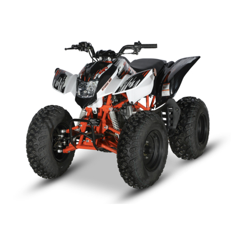
  9. KAYO MOTO A180 User manual

KAYO MOTO A180 User manual

KAYO MOTO
A180
Assembly Manual
WWW.KAYOMOTO.COM
1.The above picture shows the tools needed to
unpack and install the vehicle
①Torque wrench
② 27mm socket
③ 6mm hexagon socket
④ 17mm socket
⑤ 12mm socket
⑥ 14mm socket
⑦ Phillips screwdriver
⑧ Needle nose pliers
⑨ Additional rod for electric wrench socket
⑩ No. 10-12 wrench
⑪ No. 8 T-socket
⑫ No. 12-14 wrench
⑬ No. 10 T-socket
⑭ 10mm socket
⑮ 21mm socket
⑯ 13mm socket
2. Remove the straps and cardboard cover.
3. Take out the parts attached on the vehicle
and the packaging iron frame, remove the iron
frame screws, wait for subsequent installation.
4. The parts shown above need to be subsequently
installed on the vehicle.
5. Above photo shows the accessories in the
carton. Please read the user’s manual(D)
before assembling.
Name
Quantity
A
Front brake disc
2
B
Rubber dust cap
4
C
Rear L&R reflector
2
Bracket
2
D
User’s manual
1
E
Air pressure gauge
1
F
Bracket for gear indicator cover
1
G
Spark plug socket
1
H
Cable tie
2
I
Front brake
hardware
flange bolt M8*25
4
spring washer
Φ8*13*2
4
washer
Φ8*16*1.5
4
J
Front wheel
hub hardware
slotted nut
M14*1.5*H18
2
washer Φ15*28*1.5
2
cotter pin 3*20
2
K
Steering pull
rod hardware
slotted nut
2
washer
Φ10*20*2
2
cotter pin 2.5*24
2
L
Front fork
hardware
bolt M10*40*1.25
2
nut M10*1.25
2
M
Plastics cover
hardware
screw M6*20
2
washer Φ5.5*14.5*2
2
nut M6 20*16*1.0
2
N
Rear axle
hardware
slotted nut M18*1.5
2
cotter pin 4*28
2
dust cap washer
Φ18.5*53*2
2
spring washer
Φ18*27*4.5
2
O
Sub-frame bolt M8*16
3
P
Front wheel rim lock nut M10*1.25
8
Q
Front plastics
hardware
screw M6*16
2
rubber washer
Φ5.5*15*2
2
nut M6
2
R
Front bumper bolt M8*12
4
S
Gear indicator bolt M5*12
2
T
Rear reflector bracket bolt M8*12
2
6. The picture shows the details of the
hardware in the accessory box
7. Install bracket for gear indicator cover(F),
use tool ①③ to tighten handlebar clamps, the
distance between the two ends of the mark is
close, tighten evenly, first start by hand
tightening all four clamp bolts. (The handlebar
is tilted 3-5° vertically to the rear after
installation, and the torque is required to be
25-30N.m)
8. Use tool ⑦ to tighten the rear reflector bracket
bolt (T).
9. Use tool ⑦ to install the combination switch
10. Use tool ⑩⑫ to remove the screws fixed on the
rear axle, and then use tool ⑧ to remove the
screws fixed to the front of the frame (The front
frame fixing wire is a temporary solution, and the
subsequent packaging is fixed with bolts)
11. Put the vehicle on the stand for easy
installation of other accessories.
12. Use tool ①⑫⑯ to tighten front fork bolt and
nut(L).
(torque requirement 49-59N.m)
13. Install the pull rod
on the steering knuckle, then install slotted nut
and washer(K). Use tool ①④ to tighten, and
insert the cotter pin(K), the bending angle is
greater than 180°(torque requirement
49-59N.m)
14. Install front brake disc(A) on the steering
knuckle, use tool ①⑮ to tighten slotted nut(J), and
insert the cotter pin(J), the bending angle is greater
than 180°.
15. Install the front disc brake caliper on the
steering knuckle, use tool ①⑤⑨ to fasten the
front brake bolt, spring washer, washer (I)
(torque requirement 25-30N.m)
16. Please refer to user’s manual (D) for air
pressure requirements. Use compressed air to
inflate the tires and use the air pressure gauge (E)
to inflate to the standard value of 5psi.
17. Install the front wheel on the front hub, and
use tool ①⑥ to tighten the front wheel rim lock
nut(P), and install rubber dust cap(B). (torque
requirement 60-68N.m)
18. Align the rear wheel with the splines and push
on the rear axle, with the air nozzle cap facing
outward, install the slotted nut, dust cap washer
and spring washer(N), and use ①② to lock them.
Then insert the cotter pin(N), the bending angle is
greater than 180° and install rubber dust cap(A).
(torque requirement is 77-92N.m)
19. Use tool ①⑤ to tighten the front bumper
bolt(R). (torque requirement is 25-30 N m)
20. Install the sub-frame, use tool ①⑤⑨ to tighten
the sub-frame bolt(O). (torque Requirement
25-30N.m)
21. Install plastics
cover nut(M) on the plastics, and then use ⑦ to
tighten the screw and washer(M).
22. Pull the latch as above shown and remove the
seat cushion, waiting for the subsequent installation
of the battery.
23. Use tool ⑩⑬ to remove the battery holder,
install the battery and fix the battery holder,
connect the positive and negative poles as
shown in the picture, use tool ⑦ to tighten the
screws, then install the seat. (Red is positive,
black is negative)
24. Use tools ⑦⑩ to tighten the front plastics
screw, washer and nut(Q)
25. Take out rear L&R reflector bracket(C)
from the accessory box and use tool ①⑤⑨ to
tighten the screws(T) of the reflector bracket
and install the reflector. (torque requirement
25-30N.m)
26. Unscrew the fuel tank cap, add gasoline, and
tighten the fuel tank cap clockwise.
27. Please read the user’s manual (D) carefully
before riding to better understand the
performance of the vehicle.

Other KAYO MOTO Offroad Vehicle manuals
KAYO MOTO AU125-2 User manual

KAYO MOTO

KAYO MOTO AU125-2 User manual

KAYO MOTO S200 User manual

KAYO MOTO

KAYO MOTO S200 User manual

KAYO MOTO S200 User manual

KAYO MOTO

KAYO MOTO S200 User manual

KAYO MOTO AU150 User manual

KAYO MOTO

KAYO MOTO AU150 User manual

KAYO MOTO A200 User manual

KAYO MOTO

KAYO MOTO A200 User manual

KAYO MOTO A150 User manual

KAYO MOTO

KAYO MOTO A150 User manual

KAYO MOTO AU180 User manual

KAYO MOTO

KAYO MOTO AU180 User manual

KAYO MOTO AU200 User manual

KAYO MOTO

KAYO MOTO AU200 User manual

KAYO MOTO AY70-2 User manual

KAYO MOTO

KAYO MOTO AY70-2 User manual

KAYO MOTO AT125-2 User manual

KAYO MOTO

KAYO MOTO AT125-2 User manual

Popular Offroad Vehicle manuals by other brands

Ski-Doo 2008 Rev series Operator's guide

Ski-Doo

Ski-Doo 2008 Rev series Operator's guide

Volvo XC 90 quick guide

Volvo

Volvo XC 90 quick guide

Arctic Cat 2009 366 Service manual

Arctic Cat

Arctic Cat 2009 366 Service manual

BOMBARDIER DS 650 Shop Manual

BOMBARDIER

BOMBARDIER DS 650 Shop Manual

Polaris Sportsman BIG BOSS 6x6 Owner's manual for maintenance and safety

Polaris

Polaris Sportsman BIG BOSS 6x6 Owner's manual for maintenance and safety

Polaris RZR XP 1000 2016 owner's manual

Polaris

Polaris RZR XP 1000 2016 owner's manual

Arctic Cat ZR 3000 Operator's manual

Arctic Cat

Arctic Cat ZR 3000 Operator's manual

BOMBARDIER 2006 outlander max 400 Operator's guide

BOMBARDIER

BOMBARDIER 2006 outlander max 400 Operator's guide

Thumpstar ATV 70CC owner's manual

Thumpstar

Thumpstar ATV 70CC owner's manual

Yamaha SL338D Service manual

Yamaha

Yamaha SL338D Service manual

Polaris RZR RS1 2021 Owner's manual for maintenance and safety

Polaris

Polaris RZR RS1 2021 Owner's manual for maintenance and safety

Polaris Sportsman 9922475 owner's manual

Polaris

Polaris Sportsman 9922475 owner's manual

COAST MACHINERY MARSH MASTER 2015 operating & maintenance manual

COAST MACHINERY

COAST MACHINERY MARSH MASTER 2015 operating & maintenance manual

Arctic Cat Crossfire 700 EFI (EB) 2006 Service manual

Arctic Cat

Arctic Cat Crossfire 700 EFI (EB) 2006 Service manual

Polaris Ranger 900 XP installation instructions

Polaris

Polaris Ranger 900 XP installation instructions

ODES UTV Series manual

ODES

ODES UTV Series manual

ENVO ELECTRIC SNOWKART user manual

ENVO

ENVO ELECTRIC SNOWKART user manual

BOMBARDIER Skandic 377 Operator's manual

BOMBARDIER

BOMBARDIER Skandic 377 Operator's manual

manuals.online logo
manuals.online logoBrands
  • About & Mission
  • Contact us
  • Privacy Policy
  • Terms and Conditions

Copyright 2025 Manuals.Online. All Rights Reserved.