KBB KS1000 User manual

Sliding door drive unit
KS1000
Assembly-and operating instructions
KBB Automated Entrances Inc.
ООО "АВТОМАТИКА"
http://avtomatika.ooo/

1
KS1000 Assembly-and operating instructions
1. Summary
1Instruction of this manual--------------------------------------------------------------------3
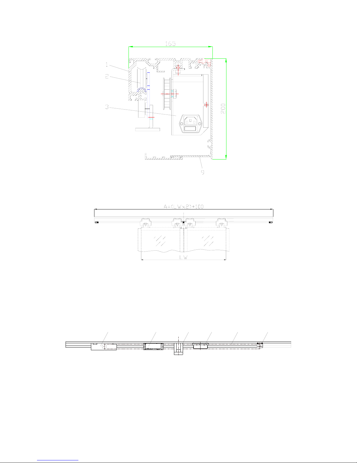
1.1Product Description---------------------------------------------------------------------------3
1.2Application area--------------------------------------------------------------------------------5
1.3Technical parameters--------------------------------------------------------------------------5
1.4Security----------------------------------------------------------------------------------------- 5
2. Basic Assembly
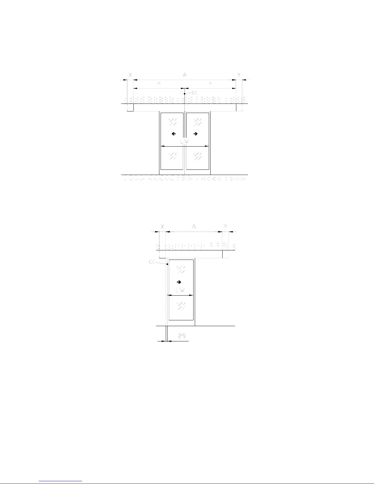
2.1 Assembly types ----------------------------------------------------------------------------------- 6
2.2.Assembly instruction -----------------------------------------------------------------------------7
3. Components Installation
3.1 Installation of running carriage subassembly --------------------------------------------- 11
3.2 Installation of drive Unit--------------------------------------------------------------------- 14
3.3 Installation of reverse wheels---------------------------------------------------------------- 14
3.4 Installation of toothed belt----------------------------------------------------------------- 15
3.5 Installation of control unit-------------------------------------------------------------------- 16
3.6 Installation of control elements--------------------------------------------------------------16
4. Adjustment
4.1 Preparation before operation------------------------------------------------------------------17
4.2 Electrical settings-------------------------------------------------------------------------------17
4.3 System start-up----------------------------------------------------------------------------------18
4.4 Interruption of self-inspection-----------------------------------------------------------------18
Functions of operating device
5.1 General--------------------------------------------------------------------------------------------19
5.2 PSA controller(Option)---------------------------------------------------------------------19
5.2.1 Operating Functions(1st level)---------------------------------------------------19
5.2.2 Setting functions(2nd level)------------------------------------------------------ 20
5.2.3 Programming function(3rd level)----------------------------------------------------21
5.2.4 problem indication(4th level)-----------------------------------------------------26
5.3Security Device--------------------------------------------------------------------------------29
5.4Main input & output terminal functions----------------------------------------------------29
5.5Interlock functions-----------------------------------------------------------------------------30
5.6Attention details--------------------------------------------------------------------------------31
3
3
5
5
5
6
7
11
14
14
15
16
16
17
17
18
18
19
19
19
20
21
26
29
29
30
31

2
6. Maintenance and troubleshooting
6.1 Security and guarantee----------------------------------------------------------------------------33
6.2Maintenance--------------------------------------------------------------------------------------33
6.3Trouble shooting---------------------------------------------------------------------------------33
6.4KS1000 spare parts list--------------------------------------------------------------------------34
6.5Environment protection treatment--------------------------------------------------------------35
Appendix
Appendix1:Drive case installation--------------------------------------------------------------------36
Appendix2: Two-wing Doors installation--------------------------------------------------------------37
Appendix3: Left-opening door Installation ------------------------------------------------------------38
Appendix4: Right-opening door Installation-----------------------------------------------------------39
Appendix5: Wire connection drawing of control unit------------------------------------------------ 40
Appendix6: Wire drawing of Battery electronic-mechanical lock-----------------------------------41
Appendix7: Wire drawing of start-up signal -----------------------------------------------------------42
Advice
<<Assembly and Operating instructions>> defines not only the responsibilities of quality
guarantee between KBB and Users, but also the stipulation of generating and ceasing right
& obligation in after-sales service respect. Please seriously read <<Assembly and Operating
instructions>> before applying to KBB products
33
33
33
34
35
36
37
38
39
40
41
42

3
1. Summary
1.1Instruction of this manual
zThe manual offers instructions for the installation, adjustment, the maintenance, and
troubleshooting.
zThe manual is just for professional persons from Metal construction and electronic
technology
zThe manual includes the instruction to main components and all specifications of KS1000
sliding door
zThe instructions for optional device are included in the deliveries of optional device of
KS1000 Sliding door drive Unit.
zUses the following signs as important mark of certain dangers and significant explanation
:
Warning:
Be danger to the life and limb
Attention:
Could cause components to be damaged or malfunction
Notes:
Clues that facilitate the work
zKBB keep the right to modify its products. If some modification is done, we will not inform
users about it。
zAll dimensions unit without label are “ mm”
1.2Product Description
Sliding door drive unit use modular design, including DC motor, microprocessor control unit,
control panel, individual module, and optional components that required in the order. The drive
unit is connected with an electronic cable.
The structure of sliding door drive unit sees below:

4
1、Carrier profile 2、Running gear 3、Drive unit
Figure 1.1 Section drawing of installing drive unit
A Overall length of guide way profile
LW Valid passage width
Figure1.2Installationdrawingofdoorleaves
CE
346
58
7
1 Carriage profile
2Running gear
3Driveunit
4Control unit
5Electron-mechanic lock
6Spare battery
7Dentiform belt
8Reverse wheel

5
9Hinge-shape covering
CE Closing point
Figure 1.3 Spare parts distributing drawing inside drive unit
1.3 Application area
Type Specification Net passage width Max.weight
/sliding door
Max.speed
(according to
weight of door)
Single wing
(left or right opening)107..115 700-1500mm 140kg 0.45-0.65m/s
Double wings 208..230 800-3000mm 90k g 0.45-0.65m/s
Two-wings double drive
door 210..230 1000-3000mm 140k g 0.45-0.65m/s
Two-wings telescopic
door
(Left or right opening)
211..230 1100-3000mm 90k g 0.45-0.65m/s
Four-wings telescopic
door 414..440 1400-4000mm 60k g 0.45-0.65m/s
Four- wings double
drive telescopic door 419..440 1900-4000mm 90k g 0.45-0.65m/s
1.4 Technical parameters
The socket and main cable supplied by user 220V+10%,50/60Hz,10A
Powerconsumption 200W
Max driving power(static)150N
In case of power failure, the spare battery guarantees full operation for: 30min
Temperature of working environment -30℃~ +50℃
The product only is used in dry rooms Max relative humidity90%
Protectionlevel IP23
1.5 Security
Once a sliding door is applied, the max. opening and closing speeds are automatically adjusted
depending on the wing weight. Therefore, the door users are not necessary to do any presetting
The entire security device has to be checked to ensure their faultless functions
Attention: The application limits of KS1000 sliding drive unit are defined in the sales documents.
Any application beyond the limits is not allowed.

6
2. Basic Assembly
2.1 Assembly Types
There are 6 assembly types available.
A The assembly of lintel that made up of carrier profile and supporting profile.
B Lintel assembly with angle.
C Hanging assembly of steel board structure.

7
D Hanging assembly in corner
E Hanging on ceiling assembly in corner
F Hanging on Ceiling assembly with steel tube
2.2 Assembly

8
Assembly closing point CE determining the assembly position of the carrier profile
Double winged sliding door
Single-winged sliding door
The assembly way of opening from the right.(mirror image for version when opening from the
left)
A Min. carrier profile length (2+LW+100)
X、Y Possible over-length of carrier profile
LW valid passage width
CE Closing edge
The following description is assembly example for double winged sliding door systems. It
describes the assembly process of supporting frame and carrier profile. Other types of systems are
assembled as the same on CE basis.

9
Assembly carrier profile
1.Mark out the closing point CE on the carrier profile. Place the carrier frame on the floor and
use gradienter to adjust the level and mark out the water level line UK
CE Closing edge
UK water level line that cause from the joint of carrier profile’ bottom edge and flatness
floor
LH Headroom
G
r
a
d
i
e
n
t
e
r
T
y
p
e
A
:
L
H
-
1
0
T
y
p
e
B
:
L
H
+
2
0
T
y
p
e
B
=
4
9
CE
F
l
a
t
r
u
l
e
r
X
T
y
p
e
A
=
1
3
5
I
M
a
g
n
i
f
i
e
d
d
r
a
w
i
n
g
M
e
t
e
r
e
l
e
v
a
t
i
o
n
2.According to the following data, mark out the line L.
Assemble type A:LH-10 Assemble type B:LH+20
3.Draw the lower assembly edge of carrier profile。
4.Draw the vertical line of L line through the two centers of long-round holes at both ends of
carrier profile, and mark out the intersection point Q
Magnified drawing
Type A=135
Type B= 49
Type A:LH-10
TypeB: LH+10
Gradienter Flat ruler
Attention: Horizontal deviation <1mm/m。

10
CE
水平仪
平尺
5.Drill the mounting holes for screws M8.
6.Use screws and thinner washer to fix supporting profile (with type A) and carrier profile (with
style B). Notice to align the lower assembly edge M with closing point CE.
Note:After installation of carrier profile, install the running carriage set on carrier
profile, and then put two blocks at two ends of carrier profile to prevent running carriage
set from sliding out.
(
承重梁
)
7.Drill the other holes
8.Assemble other fixing screws。
9.When assembling supporting profile(taking assembly type A as Example), hang the carrier
profile into supporting profile; adjust mounting holes and screw down using the screws (one
screw every 400mm)M8X20 and washers
Gradiente
Flat ruler
(Carrier Profile)
Attention: Maximum difference between closing point and M point is not more than 2mm

11
3.Components Installation
3.1 Installation of running carriage set
The basic set of running carriage includes:
Running carriage set 2 sets
Stop piece 1set
Wiper brush 2sets
Belt nip 1set
3.1.1Assembling the running carriage
1.Fix the wiper brush (4) on the outside of outer running carriage set by using the cheese head
screw M6x6 and washer
2.According to the actual situation, select the required number running carriage sets(2) to insert
the carrier profile (1) from the side. If insufficient lateral space, loose the screw.(3), and rotate
running carriage sets to the right position from the front
Figure 3.1
3.1.2 Assemble the stop piece on running carriage
Please fix the stop piece(5) on the running carriage sets(2) by using the cheese-head screw
M6X10 and washer. See Figure 3.2 & Figure 3.3.
Figure 3.2 Double-winged
Slidingdoors

12
Single-wingedslidingdoor
CE CE
Figure3.3
3.1.3 Installation of the sliding wings
1.On the running carriage screwed the sliding wings.
2.After completing the installation of the sliding wings, we should check the flexibility of the
counter-pressure roller (6) to make sure that the counter –pressure roller can be pushed
manually, when running carriage (2) is shifted, the pressure ruler (6) must be able to stop.
3.Adjust counter- pressure roller(6): slightly loose the Screw(7) about 1/2 circle, push the
screw along the slanting slots until the right position, and then screw it down. See Figure 3.4
Figure 3.4
3.1.4 The installation of stop piece on the carrier profile
3.1.4.1 Double-winged sliding door
CE
Figure 3.5
Each stop piece (25) include:
2pieces inner hexagon screw
Attention: For both winged sliding door, when sliding sings closed, the stop pieces must touch
at the closing point CE (The closing pressure applied on the sliding wings must not exceed a
maximum value of 80N) For both winged sliding door, when sliding sings closed, the stop pieces
must touch at the closing point CE (The closing pressure applied on the sliding wings must not
exceed a maximum value of 80N)

13
2 pieces washer
2 pieces M6 square nut。
Fix the stop pieces on the carrier profile directly. See Figure3.5
3.1.4.2 Single-winged sliding door
Open the door to right side(See Figure 3.6). Mirror –image for version opening to the left.
Figure 3.6
The stop piece (5-A) and the cross stop piece (8) include the following components:
2 pieces cheese-head screws
2 pieces washer
2 pieces M6 square nut.
Fix the stop pieces on the carrier profile directly. See Figure3.6
3.1.5 The installation of belt driver
The sketch map of double-winged sliding door installation:
2 Running carriage sets 9 Belt driver 10 Fastening screw
Figure 3.7
The sketch map of single-winged sliding door installation: (next page)
Attention: When the door closing, the stop piece(5) and the stop piece(8) must touch. The
closing pressure on the sliding wings must not exceed a maximum value of 80N

14
Figure 3.8
According to different assembly types, , tentatively fix the belt driver onto the running carriage
set(2) by using the component (10) ( including 2 pieces cheese-head screws M6x10 and 2
piecesφ6 washers) . The final installation is made after adjusting the door center.
3.2The installation of drive unit.
114 11 18
12
注意:
在使用两块驱动板时,请将4根跳线打开。
Caution!
For redun dant drive unit s,remove all
4 jumps on t he power board!
注意:
在维修和更换保险前,请拔掉电源线。
Caution!
Remove power cord before sercice and
fuse replacement。
100
2AT
50/60
230
电压
零件号
保险
功率
频率
序列号
跳线帽
跳线
保险 2AT
注意:
仅限在干燥环境下使用,
请不要在工作时打开驱动器盖。
Caution!
Only for dry rooms,
Do not disconnect and plug in the
internal connections and plug connection
while they are carrying voltage。
13
16/17 15
PN01231055
Figure 3.9
Refer to the figure 3.9, and mark out measure “C” on the carrier profile.
1.Insert square nuts into T groove.
2.Fasten the drive unit (12) on measure point “C” of the carrier profile with inner hexagon screws
and washer
3.Connect the cable (13) towards the groove (14), insert the line cable(15) into the groove from
the side, and then fasten the cable.
4. After assembly of the control unit, connect the cables (16) and (17).
Note: The groove(14) is applied to mount outer cables and control components, such as
PSA. Prior to fix the cable, install the components. The groove(18) is applied to
in-house connect battery control panel of control unit.
3.3The installation of the reverse wheel
Assembly position of the reverse wheel in the carrier profile is shown in appendix.
1.Insert nut into “T” groove。
Attention: Prior to fixing the driver unit on the carriage profile, check if the four cables are
plugged into the control panel.

15
2. Tentatively fix the reverse wheel(19) on the carrier profile(1) with inner hexagon screw and
washer.
The final assembly is carried out after the toothed belt has been in position. See Figure3.10
Figure 3.10
3.4Installation of the toothed belt
1.According to the attached drawing, determine the length "D” of toothed belt.
Figure 3.11
2.Slightly loosen the fasten screws。
3.Insert toothed belt(21) ends each with 3 teeth into belt clip (22)
4.Tighten the screw(20) Fig. 3.11
5.Place the toothed belt onto the drive pulley and the reverse wheel
Figure 3.12
6.Push the reverse wheel(19) outwards until toothed belt(21) lies flat. Tighten the screws
slightly(23)。
7.Use a hammer to knock reverse wheel(19) until the dentiform belt has the following tension。
See Fig. 3.13

16
Figure 3.13
8.Tighten fastening screw(23)
Setting the door Center( Take the double-winged door as example) When adjusting, belt-clip
(9) must not be tightened.。
1.Push the sliding wings(24) until distancesAand B are the same. If adjusting is insufficient ,
check the belt lengths or dimension C. See the drawing Figure 3.14 in appendix.
Figure 3.14
2.Tighten the belt clip.。
3.5 The installation of the control unit
Assembly position in the carrier profile. See the drawing in appendix
Attention: Take care when tightening the toothed belt (21). If insufficient and excessive
tension of the toothed belt increases the wear and causes noise during the operation.
Attention: Checking the door “open” stop pieces. In the open position , the sliding wing(24)
must touch the two stop pieces at the same time.
Attention: If the installation is equipped with locking combination parts and spare battery, this
unit must be installed before the control is mounted

17
Figure 3.15
1.Insert nuts(11) in “T” groove.。
2. Fasten the control unit (25) onto the carrier profile with inner hexagon screws and washer.
Tighten the screws
3. Connect the cable of drive unit (26)
3.6 The installation of control panel PSA。
The location of control panel is determined by the actual installation project. The position of inlet
box and connecting cable is determined by the requirement of customers.
1.According to the wire diagram of the control unit, connect cable plugs to the control panel
(terminals 25/26) The shielding must be fastened to the control unit.。
2.Connect the cable(30) to the PSApanel (terminals 1/2). The shielding must be fastened to
PSA metal parts.
So
1632
Rst
SET
PN01231063
W
42
Ht
Sc
8
Nt
1
ERR
PSAlock
1.To lock PSA, dismantle strap of PSA panel. 。
2.Concrete operation process: See chapter 5.。
4. Adjustment
Attention: Max length of the connecting cable is 50m. A shielded plug must be used

18
4.1 Preparation before operation
All KS1000 basic components and optional parts have been fixed and arranged .
All cables are ready for using.。
Any additional control and security units have been fixed and connected
4.2 Electrical Settings
No preliminary settings can be made before the first application.( Stop pieces must be fixed as
requirement). The running distance , the maximum permission speed , and maximum force are
set automatically during the set-up(reset) process of drive unit.
Setting-up procedure:
The setting-up procedure is implemented when the drive unit is taken in the operation for the first
time or after a reset.。
zDuring the first operation, all the values on the second level are reset to standard. After the
door has already been in operation, reset is made with “Reset” switch(Figure 5.1) or
PSA( Figure 5.2.2)
zIf the door weight exceeds approx .10kg, all the values on the second level remain
memorized after a power failure accident. It means that no setting-up procedure is needed.。
zA RESET will not influence the value of any third level
Function of setting up procedure:
zTest all the hardware components of the control unit.
zCheck all the connected components(PSApanel, electro-mechanical lock, battery board) The
door closes as far as the “closed” position with a set-up speed of 0.07m/s
zWhen the program selector is set in the locking position, sliding door is locked and remains
such status. In all the other programmed positions, the opening signal is effected
automatically.
zThe sliding door opens with a set-up speed of 0.075m/s as far as the “open” position。During
opening process, the lock is checked and average friction is determined.
zA short-time acceleration of wing checks the quality of the door. The quality determined the
maximum permission speed.
Total wing weight (KG) Maximum opening
speed (m/s)
25-125 0.65
125-160 0.55
>160 0.4
The closing speed is 66% of the maximum opening speed
Attention: If there are no light barriers fitted, two wire links must be connected at the
corresponding terminals according to the connection diagram of control unit.
Attention: For the single- winged door opening to right: soft switch 12 must to be set to ON

19
4.3 System Start-up。
1. Being the sliding wings into the center position
2. Plug in the power plug
3. On KS1000 control board, LEDS 5V/24V and POWER are lit
4. With PSA, LED 32 flashes approx.5 seconds after plug-in. The installation set its up and
remains open. LED 32 operating function manual is lit. If another LED is lit along with the
flashing LED 32, then the corresponding operating function is set. 。
4.4Interruption of self -inspection
The setting up procedure can be interrupted by the following things:
Program switch or PSAis on a locked operating position (lock/one way)
The door closes and remains. The setting up procedure can be completed only after a valid
opening command(key), or after selecting another operating function. E.g.” automatic” with
PSA: LED32 flashes and LED 1” lock”or LED2 “one way” is lit. SEE chapter 5.2.1 for
setting the operation functions.
When setting up, the door opens first: Check the assembly position of the belt joint
as per the attached drawing
The sliding door does not move: No light barrier or no strap fitted.
For PSA, red error LED flashes along with red LED. See chapter 5.2.4
KS1000 motor driver unit: safety problem.
5 Control unit and PSAcontrol panel (Optional)
5.1 General
KS1000 drive unit can be operated as follows:
5.1.1Adopt PSAcontrol panel or Program/ Selection switch (Standard)
When selecting the Program/Selection switch, input 21, 22 have four positions for your
selection: lock-up, one-way, full-open (Automatic), partial open (Automatic), (refer to chapter 5.4
Inputs).
Reset via inputs 25,26 (Press for 2 seconds at least).
PSA can be used as a temporary programming unit for function selection or fault code
analysis stated in chapter 5.2.2, 5.2.3. Upon moving the PSA, restart the power switch to preserve
the programming values.
5.1.2 PSA control board (Optional)
The inputs 25,26 connecting PSA will realize the functions of the sliding door, PSA functions
could be locked by the following mode:
1. Connect one switch (i.e.: switch lock) to the inputs 3/4 of the PSA(Refer to chapter 3.7).
2. Apply soft switch No.9 (Refer to 5.2.3) to make PSA control lock effective. An operation is
onlypossibleafterenteringthecode ,afteroneminute
without operation, the PSAresumes the locked states.
5.2 PSA control unit (Optional)
All the functions can be identified and set by the PSAcontrol panel. The Number of the LED’s on
Table of contents
Popular DC Drive manuals by other brands

Oriental motor
Oriental motor US2 Series quick start guide

SecureData
SecureData SecureDrive BT quick start guide

aqua technix
aqua technix Aqua Vario 1100 Original installation and operating manual

M-Elec
M-Elec GD-5610v1 instruction manual

M-Elec
M-Elec ADB-5K30 instruction manual

Delta
Delta MH300 user manual