KBC EE2CL User manual

QSG-EE2CL_Series-Rev1304.docx
www.kbcnetworks.com
Co yright © KBC Networks Ltd. 2014
Quick Start Guide
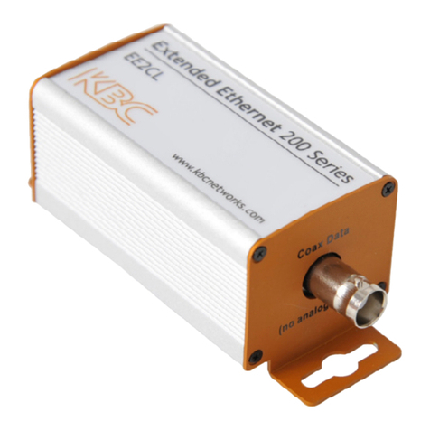
EE2CL Extended Ethernet 200 Series
Introduction
Welcome to KBC Networks’ Quick Start Guide for the EE2CL, 1 /1
Ethernet line driver and kits. This document provides some quick tips on
how to get up and running. For more detailed information see the
Downloads section below.
Features
• IEEE 8 2.3af/at compliant
• Supports up to 4 IP cameras
• Straight forward configuration
• High data rates
• LED indicators
• Transmission distances up to 1.5km
• Compact unit
• High density rack system
Downloads
Installation manual - other features and functions are described in the unabridged manual:
http://www.kbcnetworks.com/downloads
Specification Sheets:
http://www.kbcnetworks.com/downloads
Joining Guide (Where there are 2 or more master units connected to a switch)
http://www.kbcnetworks.com/downloads
System Contents
EE2CL- KT
Qty
Description
2 EE2CL Extended Ethernet unit
1 48Vdc, 1.25A Power Supply Unit
EEC2L-2KT
Qty
Description
3 EE2CL Extended Ethernet unit
1 48Vdc, 1.25A Power Supply Unit
1 BNC-T Splitter Adaptor

EE2CL-3KT
Qty
Description
4 EE2CL Extended Ethernet unit
1 48Vdc, 1.25A Power Supply Unit
1 1:4 BNC Splitter Adaptor
EE2CL-4KT
Qty
Description
5 EE2CL Extended Ethernet unit
1 48Vdc, 1.25A Power Supply Unit
1 1:4 BNC Splitter Adaptor
The following are also available as individual units:
EE2CL-1: Extended Ethernet unit
GS6 A-48-P1J: 48Vdc, 1.25A PoE Power Supply Unit
EE2CL-RK: 19” high density rack system
EE-BNC4: 1:4 BNC Splitter Adaptor
EE-BNC2: BNC T-Splitter
Equipment Required for Physical Deployment
You will need a 48Vdc, 1.25A power supply; this is supplied with each kit.
Physical Deployment
This equipment must be installed and operated in accordance with instructions found in the KBC Networks’
manual; failure to comply with these instructions will invalidate warranty.
Configuring the EE2CL
Basic configuration
1. Remove all the packaging materials and labels.
2. Choose a Master EE2CL unit; this can be any of the units purchased.
3. Connect the 48Vdc power supply to the Master EE2CL unit.
4. Check that the blue LEDs on both EE2CL units are lit.
Connecting the EE2CL to the camera
1. Mount the EE2CL near to the IP camera.
2. Connect an RJ45 cable between the camera and the RJ45 connector on the EE2CL unit.
3. Connect the coaxial cable to the BNC connector on the EE2CL unit.
4. If multiple camera units connect to a single Master unit then the 1:4 BNC Splitter Adaptor or BNC-T
adapter will be required.
Note: Depending on power requirements and cable distances power for both the Master and Slave EE2CL units
and the IP cameras can be supplied from the PS located at the Master EE2CL unit. For high power or long
distance systems, multiple PS units will be required; see the full KBC Networks’ manual for further
information.

Connecting the Master EE2CL unit at the Control Room
1. Mount the Master EE2CL unit in the Control Room.
2. Connect the coaxial cable to the BNC connector on the EE2CL unit.
3. Connect the supplied 48Vdc PSU to the EE2CL unit
4. Connect the RJ45 cable from the EE2CL unit to the Control Room equipment.
5. The green LEDs will light when a network link is established and flash to show when data traffic is being
passed.
Note: If a high density 19” rack unit is being used, please follow instructions supplied with this device.
EE2CL Status Indicators
LED Status Description
Power
ON Power is supplied to the unit
OFF No power to the unit
BNC
ON Another EE2CL unit has been
detected
FLASH Link activity
OFF No link established
PoE
ON Link active
FLASH Ethernet activity and joining
function
OFF No link established
Compliance
FCC
Changes or modifications not expressly approved by the party responsible for compliance could void the user’s
authority to operate the equipment. This device complies with Part 15 of the FCC Rules. Operation is subject to
the following two conditions:
• This device may not cause harmful interference, and
• This device must accept any interference received, including interference that may cause undesired
operation.
This equipment has been tested and found to comply with the limits for a Class A digital device, pursuant to
part 15 of the FCC Rules. These limits are designed to provide reasonable protection against harmful
interference when the equipment is operated in a commercial environment. This equipment generates, uses,
and can radiate radio frequency energy and, if not installed and used in accordance with the instruction manual,
may cause harmful interference to radio communications. Operations of this equipment in a residential area is
likely to cause harmful interference in which case the user will be required to correct the interference at his own
expense.
Industry Canada
This Class A digital apparatus complies with Canadian ICES- 3. To reduce potential radio interference to other
users, the antenna type and its gain should be so chosen that the equivalent isotropically radiated power
(E.I.R.P.) is not more than that permitted for successful communication. This device complies with Industry
Canada license-exempt RSS standard(s).
Operation is subject to the following two conditions:

• This device may not cause interference, and
• This device must accept any interference, including interference that may cause undesired operation of
the device.
Cet appareil numérique de la classe A est confrome à la norme NMB- 3 Canada. Pour réduire le risque
d’interférence aux autres utilisateurs, le type d’antenne et son gain doivent être choisies de façon que la
puissance isotrope rayonnée équivalente (PIRE) ne dépasse pas ce qui est nécessaire
pour une communication réussie. Cet appareil est conforme à la norme RSS Industrie Canada exempts de
licence norme(s). Son fonctionnement est soumis aux deux conditions suivantes:
17 Compliance
• Cet appareil ne peut pas provoquer d’interférences et
• Cet appareil doit accepter toute interférence, y compris les interférences qui peuvent causer un mauvais
fonctionnement du dispositif.
CE Marking
CE marking on this product represents the product is in compliance with all directives that are applicable to it.
This equipment may be operated in the following countries:
Great Britain and Northern Ireland, Austria, Belgium, Denmark, Finland, France, Germany, Ireland, Italy,
Netherlands, Norway, Portugal, Romania, Switzerland, Sweden
Installer Compliance Responsibility
Devices must be professionally installed and it is the professional installer's responsibility to make sure the
device is operated within local country regulatory requirements.
RoHS/WEEE Compliance Statement
European Directive 2 2/96/EC requires that the equipment bearing this symbol on the product and/or its
packaging must not be disposed of with unsorted municipal waste. The symbol indicates that this product
should be disposed of separately from regular household waste streams. It is your responsibility to dispose of
this and other electric and electronic equipment via designated collection facilities appointed by the government
or local authorities. Correct disposal and recycling will help prevent potential negative consequences to the
environment and human health. For more detailed information about the disposal of your old equipment, please
contact your local authorities, waste disposal service, or the shop where you purchased the product.
Need Help?
Visit our website http://www.kbcnetworks.com or contact your nearest KBC office or dealer:
USA
Phone: +1 949 297 493
Toll Free: +1 888 366 4276
Email:
EMEA
Phone: +44( )1622 618787
Email: [email protected]
APAC
Phone: +65 98463323
Email: apactechsupport@kbcnetworks.com
Table of contents
Other KBC Extender manuals