Keba BG3 User manual

Operation manual
Compact multi-axis system KeDrive D3
KeDrive D3-DP
Supply unit
BG3 and BG4

2
Operation Manual Supply Unit KeDrive D3-DP BG3 and BG4
ID no.: 1804.201B.0-00 Date: 08/2021
Overview, KeDrive D3-DP supply unit BG3 and BG4
Supply unit D3-DP 3xx/x BG3 Supply unit D3-DP 3xx/x BG4
D3-DP301/x-45.xx 45 kW
D3-DP301/x-90.xx 90 kW
D3-DP301/x-A2.xx 120 kW
Operation Manual KeDrive D3-DP Supply Unit BG3 and BG4
Compact multi-axis system KeDrive D3
ID no.: 1804.201B.0-00
Date: 08/2021
Applicable as from rmware version: Vx.x
The German version is the original of this documentation.
Compact multi-axis system KeDrive D3
Consisting of the KeDrive D3-DP supply unit, the DC-powered
KeDrive D3-DA axis controllers and a matching controller KeDrive D3-DU, the
Compact multi-axis system KeDrive D3 offers a high degree of solutions expertise and
exibility in the range from 2 A to 210 A rated current.
With the aid of the KeDrive D3-DE expansion module, the KeDrive D3-DA axis
controllers BG1 and BG2 can be combined with the KeDrive D3-DA axis controllers BG3
and BG4 without problems.
The addition to the KeDrive D3-DP supply modules BG3 and BG4 of the KeDrive D3-DC
capacitance module makes possible usage in even more dynamic applications.
The external switched-mode power supply (D3-DP 301/x-004x) is also available upon
request for the 24 V control supply.
Reduction of the wiring and shortening of the installation times are just as easy to
achieve as resource-saving, cost-conscious operation.
Subject to technical change without notice
The content of our documentation was compiled with the greatest care and attention,
and based on the latest information available to us.
We should nevertheless point out that this document cannot always be updated
simultaneously with the ongoing technical development of our products.
Information and specications may be subject to change at any time. Please obtain
information about the latest version in our Docu portal.

3
Operation Manual Supply Unit KeDrive D3-DP BG3 and BG4
ID no.: 1804.201B.0-00 Date: 08/2021
3.2 Mounting clearances ..........................................................................................17
3.3 Cooling the devices ............................................................................................18
3.4 Installation of the devices for wall mounting........................................................18
3.4.1 Dimensions, wall mounting model (housing with heat sink) ................19
3.5 Installation of devices for liquid cooling...............................................................20
3.5.1 Dimensions, liquid cooling model .......................................................21
3.6 Cooling circuit connection .................................................................................22
4 Electrical installation .............................................................. 23
4.1 Before you start .................................................................................................23
4.2 Effective EMC installation ..................................................................................23
4.3 Overview of the connections ..............................................................................25
4.3.1 PE connection according to DIN EN 61800-5-1 ..................................26
4.3.2 Connection principle ...........................................................................27
4.4 Electrical isolation concept.................................................................................27
4.5 AC mains connection (power supply) ................................................................29
4.5.1 Layout, X01A ......................................................................................29
4.5.2 Residual current device ......................................................................31
4.5.3 Mains fuses ........................................................................................32
4.6 Operation on TT, TN and IT system ...................................................................32
4.6.1 Operation of the KeDrive D3-DP supply unit on
TN and TT system ............................................................................32
4.6.2 Operation of the KeDrive D3-DP supply unit on IT system ................32
4.7 24 V control supply ............................................................................................33
4.7.1 Control supply with switched-mode power supply (in preparation) .....33
4.7.2 Control supply via external 24 V power supply unit ............................33
4.8 Busbars for the supply voltages .........................................................................36
4.8.1 DC link supply ....................................................................................36
4.8.2 Overview of busbars in the group........................................................37
Table of contents
1 General .................................................................................... 5
1.1 Target group .......................................................................................................5
1.2 Prerequisites.......................................................................................................5
1.3 Pictograms .........................................................................................................5
1.4 Disclaimer...........................................................................................................5
1.5 Reference documents ........................................................................................6
1.6 Order code .........................................................................................................6
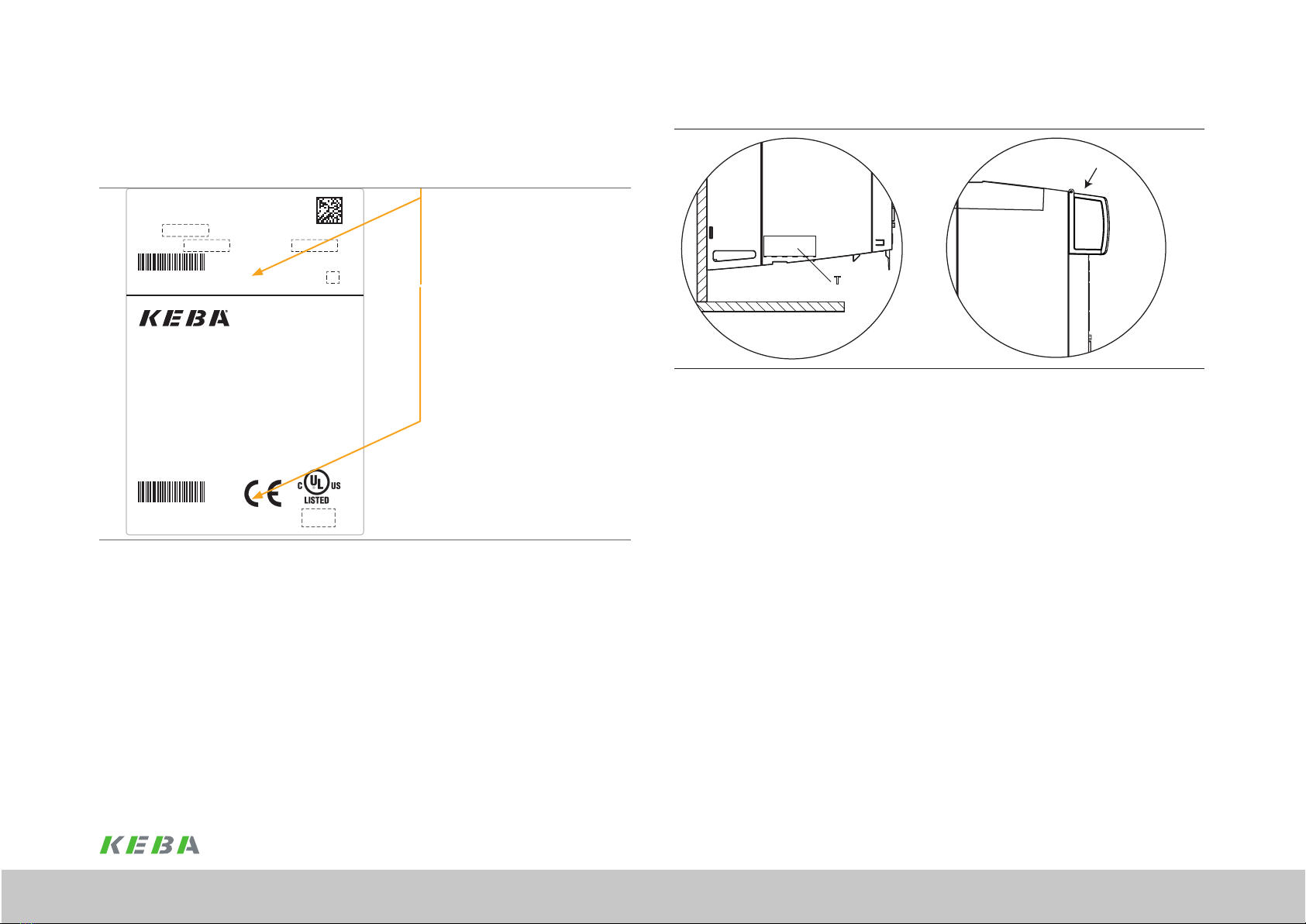
1.7 Rating plate .......................................................................................................7
1.8 Brief description ................................................................................................8
1.9 Scope of supply .................................................................................................8
1.10 Disposal .............................................................................................................8
1.11 S up po r t .............................................................................................................9
2 Safety .....................................................................................11
2.1 O v e r v i e w ............................................................................................................11
2.2 Measures for your safety ....................................................................................11
2.3 General safety instructions and warnings ...........................................................12
2.4 Intended use.......................................................................................................12
2.4.1 Repair..................................................................................................12
2.5 Misuse................................................................................................................13
2.6 Responsibility .....................................................................................................13
2.7 Relevant laws, standards and directives applied ...............................................13
2.8 Declaration of conformity ...................................................................................14
3 Mechanical installation ........................................................... 15
3.1 Notes for installation ...........................................................................................15
3.1.1 Order and arrangement.......................................................................15

4
Operation Manual Supply Unit KeDrive D3-DP BG3 and BG4
ID no.: 1804.201B.0-00 Date: 08/2021
A.6 Certication ........................................................................................................58
A.6.1 CE certication ...................................................................................58
A.6.2 UL certication (in preparation)............................................................58
A.7 Accessories .......................................................................................................58
A.8 Mains lters .......................................................................................................58
A.9 Mains chokes ....................................................................................................59
A.10 Braking resistors.................................................................................................59
4.9 Connection for braking resistor ..........................................................................38
4.9.1 Layout, terminal X30A ........................................................................38
4.9.2 Specication, terminal X30A................................................................39
4.10 Control connections (front panel)........................................................................40
4.10.1 Specication, rt-Ethernet coupler and cross-communication .............42
4.10.2 Specication, relay contact "REL Output" X23A .................................42
4.10.3 Specication, connection of temperature sensors X27A ....................42
4.10.4 Specication, connection "State" X20A ..............................................43
4.11 Commissioning ..................................................................................................43
4.11.1 Connection example, supply unit .......................................................44
5 Diagnostics ........................................................................... 45
5.1 Status indication LED ........................................................................................45
6 Design variants ...................................................................... 47
6.1 KeDrive D3-DP supply unit slave .......................................................................47
6.1.1 Purpose of the variant ........................................................................47
6.1.2 Dimensions ........................................................................................48
6.1.3 ZK +/– connection X30B .....................................................................48
6.1.4 AC mains connection D3-DP 301/x-xx02 slave ..................................48
6.1.5 Connection .........................................................................................49
A Appendix ............................................................................... 53
A.1 Technical data, supply unit BG3 .........................................................................53
A.1.1 Technical data, brake chopper BG3 ...................................................54
A.2 Technical data, supply unit BG4 ........................................................................54
A.2.1 Technical data, brake chopper BG4 ...................................................55
A.3 Ambient conditions.............................................................................................56
A.5 Power reduction at Tunom ≥ 40 °C .......................................................................57

5
General
Operation Manual Supply Unit KeDrive D3-DP BG3 and BG4
ID no.: 1804.201B.0-00 Date: 08/2021
General
1 General
The product DVD from KEBA Industrial Automation Germany GmbH contains the
complete documentation for the related product series. The documentation for a product
series includes the operation manual (hardware description), device help (software
description) as well as further user manuals (e.g. eld bus description) and specications.
The documents are available in PDF format.
1.1 Target group
Dear user,
The documentation forms part of the device and contains important information about
operation and service. It is aimed at all persons who undertake mounting, installation,
commissioning and servicing work on the product.
1.2 Prerequisites
Prerequisites for usage of the devices from KEBA:
yThe documentation on the devices is to be stored so it is legible, accessible at
all times and for the entire life of the product.
yRead and ensure you understand the documentation on your device.
yQualication: to prevent injury or damage, personnel may only work on the
device if they have electrical engineering qualications.
yKnowledge required:
− National health and safety regulations (e.g. DGUV V3 in Germany)
− Mounting, installation, commissioning and operation of the device
Work in other areas, for example transport, storage and disposal is only allowed to be
undertaken by trained personnel.
1.3 Pictograms
To help the user, in this document we use the following pictograms:
NOTE
Useful information for the user.
Reference to other documents.
You will nd the "safety instructions and warnings" used in this operation manual in
chapter 2 Safety.
1.4 Disclaimer
Following the documentation on the devices from KEBA is a prerequisite:
yFor safe operation.
yTo achieve stated performance features and product characteristics.
KEBA does not accept any liability for injuries, damage or nancial losses that result from
the failure to follow the documentation.

6
General
Operation Manual Supply Unit KeDrive D3-DP BG3 and BG4
ID no.: 1804.201B.0-00 Date: 08/2021
General
1.5 Reference documents
Note:
You will nd all reference documents for this device on our web site in the
DOCU portal:
www.keba.com
1.6 Order code
The article designation provides information about the related variant of the supply unit
supplied. You will nd the signicance of the individual characters of the order code in
the column on the left.
D3- DP 3 0 0 / A - 4 5 0 0 - 0 0 0 0 - 0 0 0 0
Module type Supply
module
Product line
Type of supply 0: Passive
Supply 0: 3 x 230 - 480 VAC
1: 3 x 400 - 480 VAC
Cooling
A: Heat sink
B: Cooling plate
C: Liquid cooling
Power
45: 45 kW
90: 90 kW
A2: 120 kW**
Control supply
24 VDC
0: None
4: 24 VDC/ 20 A on board
5: 24 VDC/ 20 A on board with power failure regulation
Braking
resistor
0: External
1: Integrated
2: Supply module as slave variant (no braking resistor)
Options 0: Not including protective varnish
1: Including protective varnish
Version 0:
1: UL
Models
Field bus 0: rt-Ethernet coupler and cross-communication
Reserved
* Upon request, ** Power for liquid-cooled variant: 140 kW

7
General
Operation Manual Supply Unit KeDrive D3-DP BG3 and BG4
ID no.: 1804.201B.0-00 Date: 08/2021
General
Position of rating plate
T
T1
Figure 1.2 Position of rating plate (T) Figure 1.3 Position of rating plate (T1)
A second rating plate (T1) with only the most important information is on the top of
the busbar cover. In this way the rating plate data can also be seen if the devices are
installed in a row.
1.7 Rating plate
On the rating plate for the device you will nd the serial number, from which you can
identify the date of manufacture based on the following key.
Mac Adr.:
SW:
FS SW1:
SN:
SN:
FS SW2:
Multiple rated equipment. See instruction manual
In:
Out:
Year:
T1
T
KEBA Industrial Automation Germany GmbH
Gewerbestr. 5-9, 35633 Lahnau, www.keba.com
D3-DP 301/A-4500-0000-0000
JJWWSXXXX
400 V AC - 480 V AC
20XX
100 A AC - 85 A AC
565V DC - 678V DC
80 A DC - 67A DC
JJWWSXXXX
MACADR
D3-DP 301/A-4500-0000-0000
A
Serial no. key:
- JJ (YY) = Prod. year
- WW = Calendar week (CW)
- S = Production site
- XXXX = Sequential no. per CW
A: Revision state
Figure 1.1 Hardware rating plate KeDrive D3-DP supply unit (example)

8
General
Operation Manual Supply Unit KeDrive D3-DP BG3 and BG4
ID no.: 1804.201B.0-00 Date: 08/2021
General
1.8 Brief description
Note:
Only the KeDrive D3-DP supply unit BG3 and BG4 is described in this opera-
tion manual.
You will nd information about the controller (KeDrive D3-DU), axis controller
(KeDrive D3-DA), capacitance module (KeDrive D3-DC) and expansion module
(KeDrive D3-DE) in the related operation manuals.
The table below shows the type, device and short designations. All three designations
can be used in the operation manual in different contexts with the same meaning.
Type designation Device designation Short designation
KeDrive D3-DA Axis controller D3-DA
KeDrive D3-DP Supply unit D3-DP
KeDrive D3-DL Charging module D3-DL
KeDrive D3-DC Capacitance module D3-DC
KeDrive D3-DE Expansion module D3-DE
- Single model D3-DE Single
- Dual model D3-DE Dual
- Dual End model D3-DE Dual End
- Size (BG) 1 and size (BG) 2 BG1+2
- Size (BG) 3 and size (BG) 4 BG3+4
* In preparation
1.9 Scope of supply
The scope of supply includes:
yKeDrive D3-DP supply unit
yPre-assembled busbar elements for 24 V control supply -USt
yBusbar elements for DC link connection (in the separate bag of accessories)
yProduct DVD with booklet
1.10 Disposal
Follow the current national regulations!
Depending on their characteristics, dispose of individual parts as:
yElectrical waste
yPlastic waste
yMetal scrap
Or engage a certied disposal organisation with scrapping.

9
General
Operation Manual Supply Unit KeDrive D3-DP BG3 and BG4
ID no.: 1804.201B.0-00 Date: 08/2021
General
1.11 Support
Address: KEBA Industrial Automation Germany GmbH
Gewerbestrasse 5-9
35633 Lahnau
If you have any questions about the project planning for your machine or the
commissioning of your device, our Helpline will provide you with quick, specic
assistance.
The Helpline is available by e-mail or telephone:
Service hours: Mo. - Fr.: 8a.m. - 5p.m. (CET)
E-mail: [email protected]
Telephone: +496441966-180
Internet: www.keba.com
Note:
You will nd detailed information about our services on our web site
www.keba.com Service

10
General
Operation Manual Supply Unit KeDrive D3-DP BG3 and BG4
ID no.: 1804.201B.0-00 Date: 08/2021
General

11
Safety
Operation Manual Supply Unit KeDrive D3-DP BG3 and BG4
ID no.: 1804.201B.0-00 Date: 08/2021
Safety
2 Safety
2.1 Overview
Our devices are state-of-the-art and comply with recognised safety regulations,
nevertheless hazards can arise. In this chapter:
yWe provide information about residual risks and hazards that can emanate from
our devices if used as intended.
yWe warn about the foreseeable misuse of our devices.
yWe refer to the necessary care and measures to be taken to prevent risks.
2.2 Measures for your safety
Note
The device is only allowed to be installed and placed in operation taking into
account the documentation for the related device family!
Our devices are quick and safe to operate. For your own safety and for the safe function
of your machine, please be sure to observe the following points:
1. Follow safety instructions for the devices:
Follow all safety instructions and warnings in the entire documentation related to the device series.
2. Electrical drives are dangerous:
xDue to electrical voltages up to 480VAC and up to 800VDC.
xEven 10min. after switching off the mains supply, dangerously high voltages of ≥ 50V may
still be present (capacitor charge). So check that electrical power is not present! See also the
warning label on the front panel on the device. Any existing additional DC link connections as
well as the connections for all components in the mains input area are to be checked in relation
to each other and in relation to earth to ensure they are not carrying any electrical power. If
necessary, all cable connections are to be discharged using suitable means.
xRotating parts.
xAutomatically starting drives.
xHot components and surfaces.
3. Protection against magnetic and/or electromagnetic elds during
installation and operation.
Persons tted with heart pacemakers, metallic implants or hearing aids etc. must not be allowed
access to the following areas:
xAreas in the immediate vicinity of electrical equipment!
xAreas where electronic components and drive controllers are installed, repaired and operated!
xAreas where motors are installed, repaired and operated!
Motors with permanent magnets pose particular hazards.
4. During installation observe the following:
xComply with connection conditions and technical data as per the documentation and the rating
plate!
xComply with standards and directives on electrical installation, such as cable cross-section,
shielding, etc.!
xDo not touch electronic components or contacts!
Electrostatic discharge can harm people and destroy components!
xTake protection measures and use protection devices as per the applicable regulations (e.g.
EN60204 or EN61800-5-1)!
xTake protection measures against electric shock according to IEC 60364-4-41:2005/AMD1:-
section 411.3. Protection measure, use additional protective equipotential bonding as described
in appendix D of IEC 60364-4-41.
xTake "device earthing" protection measure!
5. Ambient conditions
xPay attention to the information about the transport, storage and correct operation of the
devices stated in the operation manual in "A Appendix".

12
Safety
Operation Manual Supply Unit KeDrive D3-DP BG3 and BG4
ID no.: 1804.201B.0-00 Date: 08/2021
Safety
2.3 General safety instructions and warnings
DANGER! Risk of injury due to electrical power!
xCarelessness will result in serious injuries or death.
Follow safety instructions and warnings in this document and on the device.
WARNING! Risk of injury due to electrical power!
xCarelessness may result in serious injuries or death.
Follow safety instructions and warnings in this document and on the device.
CAUTION! Risk of injury or damage to the device due to incorrect operation!
xCarelessness may result in minor injuries or damage.
Follow safety instructions and warnings in this document and on the device.
WARNING! Risk of injury due to hot surfaces and components!
xCarelessness may result in serious burns.
Electronic components may become hot during operation!
Follow safety instructions and warnings in this document and on the device!
Caution! Damage due to electrostatic discharge!
xElectrostatic discharge can destroy components.
Do not touch electronic components or contacts!
Follow safety instructions and warnings in this document and on the device!
DANGER! Risk of injury due to rotating parts on the motor!
xCarelessness will result in serious injuries or death.
Follow safety instructions and warnings in this document.
Pay attention to special safety instructions and warnings that are given here in the document before a
specic action and that warn the user about a specic hazard!
Note:
The pictograms may also be used on their own with the signal word, e.g.
in the connection diagrams, however they have the same function as in the
complete warning.
DANGER WARNING CAUTION
2.4 Intended use
Our devices are components intended for stationary electrical systems and machines in
the industrial and commercial sector.
The KeDrive D3-DP supply unit BG3 and BG4 conforms to the
Low Voltage Directive 2014/35/EU
Tested and certied in accordance with applicable standards (see declaration
of conformity in chap. 2.8).
If installed in machines it is prohibited to start up intended operation until it has been
ascertained that the completed machine fully complies with the provisions of the
Machinery Directive (2006/42/EC); compliance with EN 60204 is mandatory.
Starting up intended operation is only permitted while complying with the EMC Directive
2014/30/EU.
The devices meet the requirements of the harmonised product standard EN 61800-5-1.
You will nd information about the installation of your device in chapter "3 Mechanical
installation".
2.4.1 Repair
Only have repairs undertaken by authorised repair shops. Unauthorised repairs could
lead to death, injury or damage (see previous sections). The warranty provided by KEBA
will be rendered void.

13
Safety
Operation Manual Supply Unit KeDrive D3-DP BG3 and BG4
ID no.: 1804.201B.0-00 Date: 08/2021
Safety
yThe emergency stop function (as per EN 60204-1:2006) shuts down the
supply of power to a machine, which results in the drives coasting down in an
uncontrolled manner. To avert hazards, check whether it is appropriate:
− To keep individual drives in operation
− To initiate specic safety procedures
− To incorporate a Safe Torque Off function (Safe Torque Off: movement stop
by "switching off the electrical supply" or STO)
2.7 Relevant laws, standards and directives
applied
For information about the laws, standards and directives applied by KEBA, refer to the
declaration of conformity.
Note:
Depending on the specic application for the devices, other laws, standards
and directives with provisions on "safety" may apply. If necessary, contact the
machine or system manufacturer.
2.5 Misuse
Our devices are:
yNot intended for installation in vehicles. Deployment of the device in mobile
equipment is classed as non-standard ambient conditions and is permissible
only by special agreement.
yNot intended for installation in environments with harmful oils, acids, gases,
vapours, dusts, radiation, etc.
yNot approved for usage in special applications (e.g. in potentially explosive
atmospheres or areas in which there is a risk of re).
yNot approved for usage outside a switch cabinet.
yNot approved for the generation of high-frequency onboard networks for which
the devices are not designed.
Note:
The use of devices in warehouse storage and retrieval systems that are
operated inside and outside the rack aisle on rails is allowed provided
the vibration does not exceed the maximum standard values 3M1 as per
DINEN60721-3-3.
2.6 Responsibility
Electronic devices are not fail-safe. The installer and/or operator of a complete machine
or system is responsible:
yFor ensuring the drive is rendered safe if the device fails.
yFor ensuring the safety of personnel and machinery.
yFor ensuring the complete machine is in correct working order.
yFor the risk assessment on the complete machine or system according to
DIN EN 12100:2011 and EN ISO 13849-1.
In EN 60204-1:2006 "Safety of machinery", pay attention to:
yThe topic of "Electrical equipment of machines". The safety requirements
on electrical machines dened there are intended to protect personnel and
machinery or systems.

14
Safety
Operation Manual Supply Unit KeDrive D3-DP BG3 and BG4
ID no.: 1804.201B.0-00 Date: 08/2021
Safety
2.8 Declaration of conformity
Figure 2.4 EC declaration of conformity, page 1
Figure 2.5
EU-Konformitätserklärung
Head of R&D
Seite 2 von 2
EC declaration of conformity, page 2

15
Mechanical installation
Operation Manual Supply Unit KeDrive D3-DP BG3 and BG4
ID no.: 1804.201B.0-00 Date: 08/2021
Mechanical installation
3.1.1 Order and arrangement
The following basic guidelines apply to the arrangement and installation of the supply
unit or axis controllers.
yButt mounting and alignment
− The devices can be mounted directly beside each other without any spacing.
They are fastened to the backing plate using screw joints.
Size Number of fastening points
BG3 5
BG4 9
The 24VDC control supply must be provided by an external power supply
unit (e.g. D3-DP 300/X-004x ). All devices in the axis group - supply unit
(KeDrive D3-DP), axis controller (KeDrive D3-DA), capacitance module
(KeDrive D3-DC), expansion module (KeDrive D3-DE) and the controller
(KeDrive D3-DU) - are connected together using the 24Vbusbars. Given the
same cooling concept, these connections can be made without additional
compensation measures in relation to the device depth.
− DC link busbars are available for the power supply.
− The devices must be mounted in the stipulated order and one against the
other - see Figure 3.1.
Note:
It is not allowed to connect KeDrive D3-DA axis controllers BG1 and BG2 directly to a
KeDrive D3-DP supply unit BG3 and BG4. Should it be necessary to connect axis modules of
varying size to the axis group, the KeDrive D3-DE expansion module is also to be used. Pay
attention to Operation Manual KeDrive D3-DE Expansion Module!
Note:
A maximum of 8 bus users can be connected to and operated on a KeDrive D3-DP supply unit.
An axis group is allowed to consist of a maximum of 9 bus users.
3 Mechanical installation
3.1 Notes for installation
yDuring the installation work it is imperative you avoid ...
− Drill chippings, screws or other foreign bodies falling into the device
− Moisture entering the device
ySwitch cabinet
− The device is designed only for installation in a stationary switch cabinet.
The switch cabinet must as a minimum provide IP4X protection. According
to ENISO13849-2 the switch cabinet must have IP54 protection or higher
when using the safety functions (STO and SBC) in the axis controller.
yEnvironment
− The supply unit must not be installed in areas where it would be permanently
exposed to vibration. You will nd more information in the appendix.
ySoiling
− Maximum pollution degree 2 in accordance with EN60664-1. Further
information about ambient conditions can be found in the appendix.
yEffective EMC installation
− To obtain the best result for effective EMC installation you should use a
conductive, well-earthed, chromated or galvanised backing plate.
− If backing plates are varnished, remove the coating from the contact area!
The devices themselves have a chromated zinc frame.
Note:
If the supply unit is installed in the axis group it is imperative the operation manuals for the
other devices (axis controller, controller, etc.) are also followed.

16
Mechanical installation
Operation Manual Supply Unit KeDrive D3-DP BG3 and BG4
ID no.: 1804.201B.0-00 Date: 08/2021
Mechanical installation
123456
7
D3-DP 301/x BG4
(1) MotionOne CM controller
(2) D3-DP 300/X-004x (optional) *)
(3) KeDrive D3-DP supply unit BG4
(4) KeDrive D3-DC capacitance module (optional)
(5) KeDrive D3-DA axis controller BG3
(6) KeDrive D3-DA axis controller BG3
(7) Further KeDrive D3-DA axis controller BG3 or
KeDrive D3-DE expansion module is required if coupling with
axis controllers BG1/BG2 is planned.
*) In preparation
Figure 3.2 Butt mounting sequence example conguration with KeDrive D3-DP BG4
WARNING! Risk of injury due to hot surfaces on the device (heat sink)!
Carelessness may result in serious burns or damage.
xThe device heats up very signicantly during operation and can reach temperatures of up
to 100°C. If touched there is a risk of burns to the skin. For this reason provide protection
against touching.
xPlease maintain a sufcient distance from neighbouring assemblies, particularly above the
heat sink.
NOTE:
The power supply unit D3-DP 300/X-004x must always be mounted to the left of the supply
unit KeDrive D3-DP (BG3 and BG4).
123456
7
D3-DP 301/x BG3
(1) KeDrive D3-DU controller
(2) D3-DP 300/X-004x (optional) *)
(3) KeDrive D3-DP supply unit BG3
(4) KeDrive D3-DC capacitance module (optional)
(5) KeDrive D3-DA axis controller BG3
(6) KeDrive D3-DA axis controller BG3
(7) Additional KeDrive D3-DA axis controller BG3
or
KeDrive D3-DE expansion module is are required if coupling
with KeDrive D3-DA axis controllers BG1/BG2 is planned.
*) In preparation
Figure 3.1 Butt mounting sequence example conguration with KeDrive D3-DP BG3

17
Mechanical installation
Operation Manual Supply Unit KeDrive D3-DP BG3 and BG4
ID no.: 1804.201B.0-00 Date: 08/2021
Mechanical installation
≥130 *)
≥250*)
≥300
D3-DP BG4
*) Also pay attention to the bending radius of the connection cables.
The mains connection cable for the supply unit is denitive for the clearance underneath.
Figure 3.4 Mounting clearances, KeDrive D3-DP BG4
Note:
It is imperative the minimum mounting clearances above and below are met for thermal
reasons. Depending on the connection cables used (mains cable/motor cable), the mounting
clearances may increase signicantly due to the bending radii necessary.
3.2 Mounting clearances
CAUTION! Damage to the device due to incorrect installation conditions!
The device may suffer irreparable damage if the conditions are not met.
xThe minimum clearances stated in the gure below apply to all devices (KeDrive D3-DU
controller, KeDrive D3-DP supply unit BG3 and BG4 and KeDrive D3-DA axis controller BG3
and BG4).
xThe clearance above the devices is important to prevent the build-up of heat. The clearance
underneath and at the front is necessary to permit correct cable laying.
≥130 *)
≥250*)
≥300
D3-DP BG3
*) Also pay attention to the bending radius of the connection cables.
The mains connection cable for the supply unit is denitive for the clearance underneath.
Figure 3.3 Mounting clearances, KeDrive D3-DP BG3

18
Mechanical installation
Operation Manual Supply Unit KeDrive D3-DP BG3 and BG4
ID no.: 1804.201B.0-00 Date: 08/2021
Mechanical installation
3.4 Installation of the devices for wall mounting
Step Action Comment
1.
Arrange the devices on the backing plate as per Figure 3.1.
Please also provide enough space to the left of the supply
unit (BG3 and BG4) for the MotionOne CM controller and the
D3 DP301/x-004x.
Align all devices in a line along the top edge of the devices.
It is imperative you observe the information about the butt
mounting of the devices.
This action is necessary to be able to
couple the DC link and the 24V DC using
the pre-assembled busbars.
2.
Mark out the position of the tapped holes on the backing
plate.
Drill holes in the backing plate and cut a thread for each
xing screw in the backing plate.
Pay attention to the bending radius of the
connection cables!
For hole spacing and dimensional
drawings see Table3.1 and Figure 3.6
and Figure 3.7.
3.
Mount the supply unit (BG3 and BG4) vertical and with the
KeDrive D3-DA (BG3 and BG4) butt mounted on the backing
plate.
The contact surface must be bare metal
and conductive.
Always mount the KeDrive D3-DC between
the supply unit (BG3 and BG4) and an axis
controller (BG3 and BG4).
Always mount the power supply unit
D3 DP301/x-004x to the left beside the
supply unit (BG3 and BG4).
You will nd the next steps for the electrical installation in chapter 4.
3.3 Cooling the devices
Cooling air must be able to ow through the device (interior and heat sink) without
restriction. If installed in switch cabinets with convection (= heat loss is dissipated to the
outside via the cabinet walls), always t an internal fan. If a thermal cut-out occurs, the
cooling conditions must be improved.
Figure 3.5 Cooling air ows unhindered through the device
Note:
The KeDrive D3-DP supply units BG3 and BG4 are designed for optimal heat dissipation with
fans. The speed of the heat sink fans is controlled as a function of the heat sink temperature.
The fan noise may therefore vary depending on the load.

19
Mechanical installation
Operation Manual Supply Unit KeDrive D3-DP BG3 and BG4
ID no.: 1804.201B.0-00 Date: 08/2021
Mechanical installation
Dimensional sketches, wall mounting BG3 and BG4 (heat sink)
T
T1
H5
H3
H
H4
D
B A
A1
C
H2
H1
A1
A2
Figure 3.6 Dimensional drawing, KeDrive D3-DP BG3, for dimensions see Table 3.1
D
H4
B
H5
H3
A
H1
H
H2
T
T1
C
A2 A2 A2 A2
A1
Figure 3.7 Dimensional drawing, KeDrive D3-DP BG4, for dimensions see Table 3.1
3.4.1 Dimensions, wall mounting model (housing with heat sink)
KeDrive D3-DP Supply unit BG3 Supply unit BG4
Type D3-DP301/A-45.xx D3-DP301/A-90.xx D3-DP301/A-A2.xx
Weight 13 kg 13 kg 17 kg
B (width) 164 274
H (height) 457.5 489.5
H1 378
H2 6
H3 430
H4 27.4
H5 390
T (total depth) 251
T1 222
A 27 27
A1 110 220
A2 55 55
C 4.8
D 80
Side clearance Direct butt mounting
Screws 5 x M4 9 x M4
All dimensions in mm
Table 3.1 Dimensions, wall mounting (heat sink)
NOTE:
The supply unit must always be tted to the left of the axis controllers. The highest power
axis controller should be close to the supply unit. For double-axis controllers the total power
counts. The capacitance module is always positioned in the row beside the supply unit.

20
Mechanical installation
Operation Manual Supply Unit KeDrive D3-DP BG3 and BG4
ID no.: 1804.201B.0-00 Date: 08/2021
Mechanical installation
Note:
The supply unit must always be tted to the left of the axis controllers. The highest power axis
controller should be close to the supply unit. For double-axis controllers the total power counts.
The capacitance module is mounted in a row beside an axis controller.
3.5 Installation of devices for liquid cooling
Note:
The "liquid cooling" device model is in preparation.
Step Action Comment
1.
Arrange the devices on the backing plate as per Figure 3.1.
Please also provide enough space to the left of the supply
unit (BG3 and BG4) for the KeDrive D3-DU controller and the
D3-DP 300/X-004x .
Align all devices in a line along the top edge of the devices.
It is imperative you observe the information about the butt
mounting of the devices.
This action is necessary to be able to
couple the DC link and the 24V DC using
the pre-assembled busbars.
2.
Mark out the position of the tapped holes and the pipe
ttings on the backing plate.
Drill holes in the backing plate and cut a thread for each
xing screw in the backing plate.
Pay attention to the bending radius of the
connection cables!
For hole spacing and dimensional draw-
ings, see Table 3.2 and Figure 3.8 and
Figure 3.9. .
3.
Mount the supply unit (BG3 and BG4) vertical and with the
KeDrive D3-DA (BG3 and BG4) butt mounted on the backing
plate.
While screwing the hose connections (not included in the
scope of supply) into the pipe ttings, lock the pipe ttings
using a 22 mm open-ended wrench to prevent damage due
to the application of torque to the device.
The contact surface must be bare metal
and conductive.
Always mount the KeDrive D3-DC between
the supply unit (BG3 and BG4) and an axis
controller (BG3 and BG4).
Always mount D3 DP301/x-004x to the
left beside the supply unit (BG3 and BG4).
4.
Pay attention to a perfectly sealed connection without leaks
(e.g. using Teon sealing tape).
You will nd further notes on the liquid cooling in chap. A.4,
p. 80.
You will nd the next steps for the electrical installation in chapter 4.
This manual suits for next models
1
Table of contents
Other Keba Power Supply manuals