Keit IRmadillo DOC1049R User manual

DOC1049R
22 February 2024, 12:07
DOC1049R IRmadilloNA User
Manual - Hardware
Model Number: ASM0627-09-N-Cx-O-Gx-D3x
www.keit.co.uk

Page 1
DOC1049R (22 February 2024 12:07)
www.keit.co.uk Back to Table of Contents
Table of Contents
1.1. Purging the IRmadilloNA.........................................................................................2
1.2. Avoiding fouling ......................................................................................................3
1.3. Checking for warnings and checking the probe is clean..........................................5
1.3.1. Cleaning instructions........................................................................................5
1.3.2. Recognising if the probe is clean .....................................................................6
1.4. Taking a background ..............................................................................................7
2. Maintenance..................................................................................................................8
2.1. Spectrum health......................................................................................................8
2.1.1. Use at high temperature ..................................................................................8
2.1.2. Emitter ageing..................................................................................................9
2.2. Remote health check..............................................................................................9
2.3. Cleaning the fibre optic data cable connectors........................................................9
2.3.1. Cleaning the Souriau fibre-optic connectors...................................................10
3. Components ................................................................................................................13
3.1. Storage conditions................................................................................................13
4. Accessories .................................................................................................................14
4.1. Sample cell - ASM1398 ........................................................................................14
4.1.1. Maintenance..................................................................................................14
4.1.2. Cleaning ........................................................................................................14
4.2. Flow cells..............................................................................................................15
4.2.1. High flow cell - ASM1392...............................................................................15
4.2.2. Low flow cell - ASM1222................................................................................16
4.3. Inclined Stand –ASM0916....................................................................................18
4.3.1. Safety............................................................................................................18
4.3.2. Installation .....................................................................................................19

Page 2
DOC1049R (22 February 2024 12:07)
www.keit.co.uk Back to Table of Contents
This document should be read in conjunction with DOC1048R IRmadilloNA User Manual –
Safety.
1.1. Purging the IRmadilloNA
The IRmadilloNA spectrometer is designed to be continuously purged. This eliminates any
interference in operationcaused by changing levels of water vapour and carbon dioxide (CO2)
within the instrument, both of which interact strongly with infrared (IR) light.
The IRmadilloNA is fitted with purge inlets on the probe and spectrometer body. The Inlets are
shipped with blanking plugs that need to be removed before use. There are breathers on both
the probe and spectrometer body.
Figure 1: Purge inlet and outlet locations on ASM0627-09
The ideal purge gas is dry nitrogen. Alternatively, dry air from a purge gas generator can be
used. The output from this purge gas generator should have a minimum quality according to
ISO8573-1:2010 of Class 1:2:1 (dust:water:oil) or better. Keit can recommend suitable
generators may include an internal compressor or use factory-supplied compressed air with a
minimum quality of Class 4:4:4 (dust:water:oil).
NOTE
REMARQUE
All FTIR spectrometers are very sensitive to water vapour and
carbon dioxide. Even in well-controlled environments, e.g.,
laboratories, environmental changes can be large enough to
cause significant changes in the spectrum. We STRONGLY
recommend purging the instrument at all times.
Tous les spectromètres FTIR sont très sensibles à la vapeur d’eau
et au dioxyde de carbone. Même dans des environnements contrôlés
(des laboratoires, par exemple), les changements dans
l’environnement peuvent être suffisants pour causer des variations
de spectre significatives. Il est VIVEMENT recommandé de toujours
purger l’instrument.

Page 3
DOC1049R (22 February 2024 12:07)
www.keit.co.uk Back to Table of Contents
To purge the instrument:
•Remove the blanking plugs from the gas purge inlets on the instrument probe and
body; these are push fit connectors.
•Connect either a 4mm or 5/32” diameter stainless steel or PTFE hose to the purge inlet
ports.
•Ensure the gas tubes are connected to a suitable gas supply via a flow meter (we
recommend 1 adjustable flow meter per instrument)
•Adjust the total flow to 0.5 - 2 litres per minute (The pressure drop through the unit is
<1 barg).
•Do not turn off the purge during normal operation; this will impact the instrument’s
performance.
•If the purge tubing is disconnected, the blanking plugs must be fitted to the inlet
connections on the probe and body to maintain the IP rating and exclude dust.
The IRmadilloNA requires a stabilisation period of >12 hours once powered on and purging
has started. This is to allow the internal components to reach a stable temperature and
complete purging. Once fully purged the instrument is very robust against changes in ambient
conditions, provided the purge gas supply is maintained.
1.2. Avoiding fouling
The diamond window at the tip of the probe must be in contact with process fluid to give a
measurement. Even a thin layer of scaling or fouling will prevent the IRmadilloNA from being
able to ‘see’ the process fluid.
To minimise the risk of fouling of the diamond window, we recommend taking the following
steps during installation:

Page 4
DOC1049R (22 February 2024 12:07)
www.keit.co.uk Back to Table of Contents
Figure 2: Installing the IRmadilloNA in a fouling environment.
1. Particularly for continuous processes, install the IRmadilloNA in a bypass loop which can
be isolated using valves A and B. This makes it easy to retract the IRmadilloNA for manual
cleaning if required without the need to interrupt the process flow.
2. Direct the flow through the IRmadilloNA’s bypass loop by blocking or restricting the ‘main’
flow unless the bypass loop is to be isolated (valve C). Alternatively, this may be achieved
by mounting in a pump bypass loop (offtake from pump discharge and return to pump
suction).
3. Maximise theflow velocity pastthe IRmadilloNA by installing in areduced-diameter section
of the pipe. The minimum flow velocity should be 1.5 m/s (5 ft/s).
4. Install the IRmadilloNA so that the probe tip is fully in the flow. We recommend putting the
probe tip as close to the centre of the pipe as possible.
5. The direction of flow should be vertically upwards. This both minimises the risk of air
bubbles becoming trapped around the probe tip and reduces the risk of settling of any
sediment that is present.
6. To increase the pressure, install the IRmadilloNA after a pump. Higher pressure minimises
the risk of sedimentation and bubbles.
7. Where possible, install the IRmadilloNA at a location where the process conditions are
less prone to fouling. Depending on your process chemistry, this may be achieved by
choosing a high temperature location and using heat tracing and insulation to avoid
localised cooling. Higher process temperatures often maximise the solubility of potential
fouling substances.

Page 5
DOC1049R (22 February 2024 12:07)
www.keit.co.uk Back to Table of Contents
8. Fit ports either side of the IRmadilloNA’s install point to allow clean-in-place or flushing
with a suitable cleaning fluid.
1.3. Checking for warnings and checking the probe is clean
When you have connected to the powered-on IRmadilloNA the KeitSpec application should
load automatically (within 3 minutes). It is important to confirm that the system is working
without errors: information on IRmadilloNA warnings and errors can be found in DOC0893
KeitSpec Software User Manual, section 1, Getting Started.
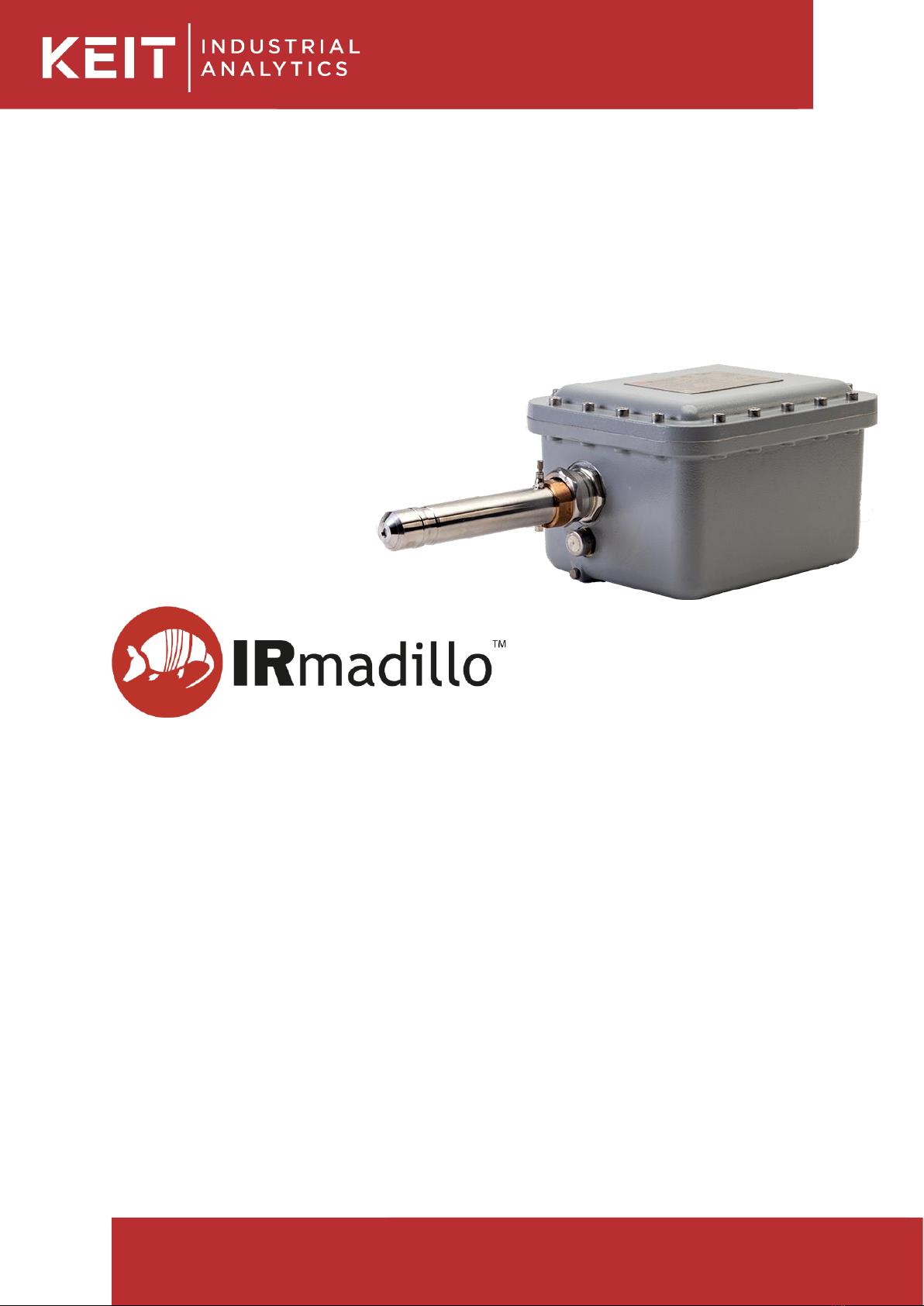
Once the system is set up without errors, the probe tip must be cleaned, and a background
spectrum must be taken before insertion into the vessel or pipe. If the probe is guaranteed
clean, the factory background scan shipped with the instrument –and saved to the desktop of
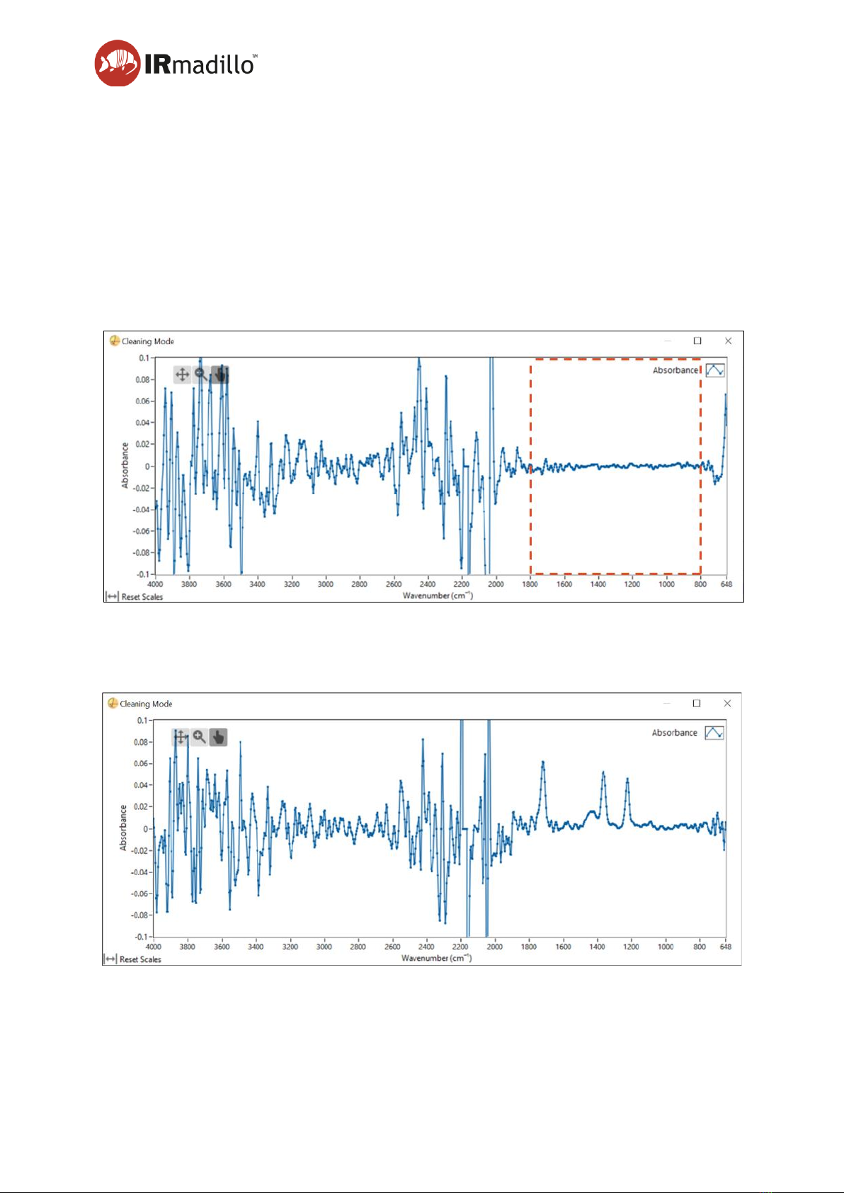
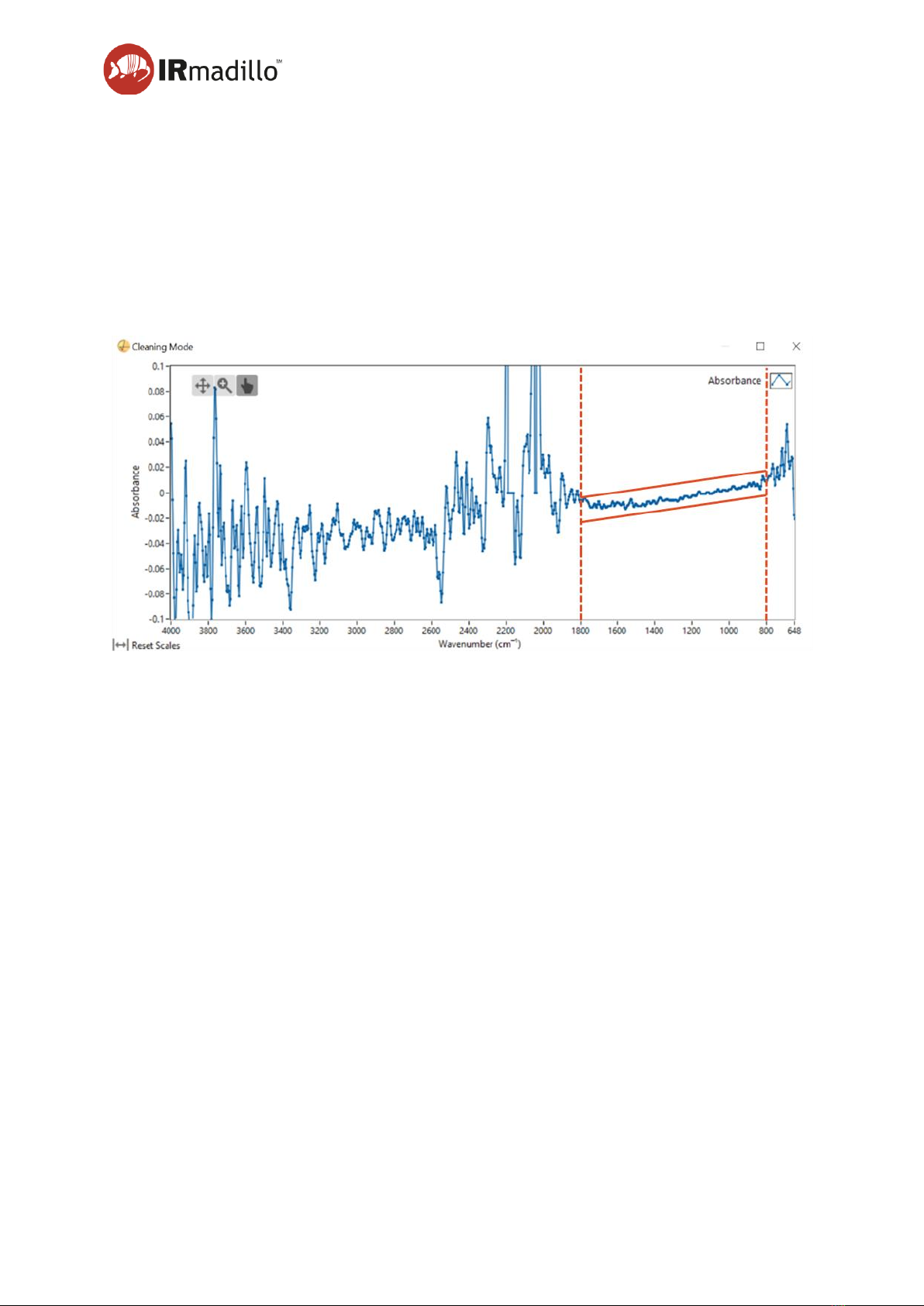
the controller –can be used. Cleanliness of the probe tip is important to performance; if you
suspect fouling or scale build-up, perform a clean appropriate to your environment.
1.3.1. Cleaning instructions
Rinse the ATR element with a suitable solvent. The choice of solvent will depend on your
process. You may fully immerse the ATR in solvent if needed. The following are suitable:
•Water
•Acetone
•Alcohols
•Surfactant solutions
•Alkanes (hexane, cyclohexane etc…)
•Ethers
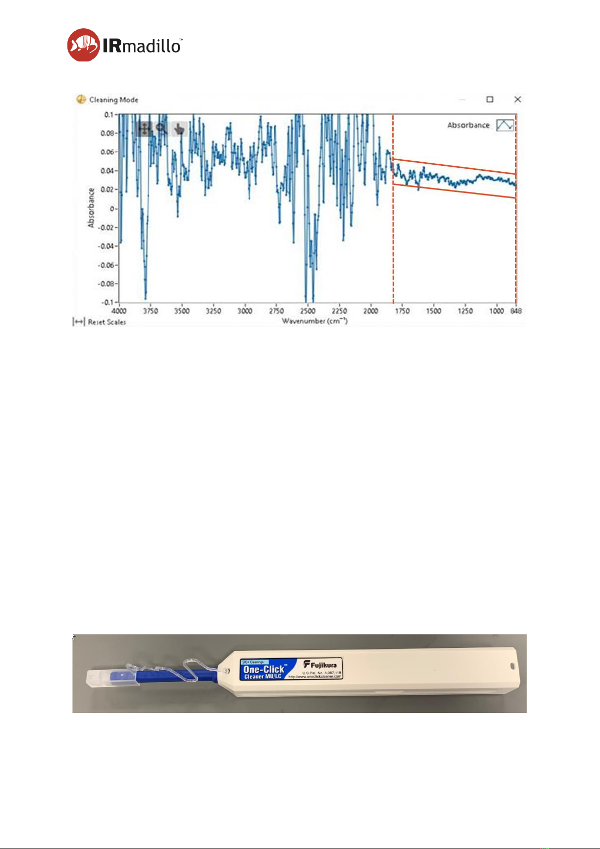
Once exposed to a suitable solvent, wipe the ATR with a clean cloth. The metal tube of the
probe can also be cleaned by wiping with a cloth.
For hard-to-remove fouling (such as biofilms or dried-on chemicals) Keit recommends an
oxidative acid clean. First, clean the ATR using the methods outlined above, then perform the
following: Souriau in-line plug
•If you have purchased one, place the PTFE sample cell on the end of the probe and
fill with ~4ml of 1 M nitric acid solution. If you have not purchased one then please
contact support@keit.co.uk for further information.
•Leave to soak for 1 hr
•Carefully remove the acid using a pipette and fill the sample cell with water
•Remove the water using a pipette
•Remove the sample cell and rinse the ATR again with water
•Carefully wipe the ATR with a cloth
It may be necessary to repeat the cleaning steps again if the contaminant has only been
partially removed.
In some cases, it may be necessary to perform an alkali clean on the probe. First clean the
ATR using the methods outline above, then perform the following:
•Place the PTFE sample cell on the end of the probe and fill with ~4ml of 1 M sodium
hydroxide solution
•Leave to soak for 1 hr
•Carefully remove the alkali using a pipette and fill the sample cell with water
•Remove the water using a pipette

Page 6
DOC1049R (22 February 2024 12:07)
www.keit.co.uk Back to Table of Contents
•Remove the sample cell and rinse the ATR again with water
•Carefully wipe the ATR with a cloth
It may be necessary to repeat the cleaning steps again if the contaminant has only been
partially removed.
1.3.2. Recognising if the probe is clean
When looking to see if the instrument is clean, the primary area of interest within the spectrum
is between 800 and 1800 cm-1. This section ofthe absorbance plot shouldmaintain a relatively
flat line with no consistently repeating peaks. Cleaning Mode can be used to see the effects
of the cleaning process in real time –see DOC0893 KeitSpec Software User Manual, Section
2, The Spectrometer Tab.
Figure 3: A clean probe showing no significant peaks within the 800 to 1800 cm-1 region.
Several sharp peaks in the region 800-1800 cm-1 indicate that the probe has not been cleaned
properly.
Figure 4: Sharp spikes within the region indicating an unclean probe

Page 7
DOC1049R (22 February 2024 12:07)
www.keit.co.uk Back to Table of Contents
A peak at 1400 cm-1 indicates that there is some water on the probe. This could indicate poor
purge quality.
Figure 5: Peak indicating the water in the spectrum
A negative peak indicates that although the probe is clean now, it was not clean when the
background was taken. Another background must be taken before any spectra can be
measured.
Figure 6: Negative peaks indicating the background was taken when the probe was unclean or not fully
purged.
1.4. Taking a background
FTIR requires the collection of a background spectrum (also called a reference or baseline
scan) before any absorption scans can be performed. This must be performed before the
probe is inserted into the reaction/process of interest. The process for collecting a reference
scan can be found in DOC0893 KeitSpec Software User Manual, Section 1, Getting Started.

Page 8
DOC1049R (22 February 2024 12:07)
www.keit.co.uk Back to Table of Contents
2. MAINTENANCE
Probe accessories may contain O-rings, which we recommend replacing annually or, where
worn or damaged, more frequently. See Section 4 Accessories for more information on
accessories.
2.1. Spectrum health
The spectrum can be used as a good indication of the health of the instrument.
2.1.1. Use at high temperature
Figure 7: Probe is heated causing the spectrum to tilt
In Figure 7, the spectrum is tilted, with positive absorbance at lower wavenumbers and
negative absorbance at high wavenumbers and the spectrum is not flat in the region 800-
1800cm-1. This indicates that the probe tip is at a higher temperature now than it was when
the background was taken. This may cause chemometric models to give incorrect results
unless the model uses an appropriate pre-treatment to remove the effect. Any model built by
Keit will have this taken into account.

Page 9
DOC1049R (22 February 2024 12:07)
www.keit.co.uk Back to Table of Contents
2.1.2. Emitter ageing
Figure 8: Spectrum is tilted showing signs of emitter ageing
The infrared emitter in the probe is expected to age over its lifetime. The results of this can be
seen in Figure 8: the spectrum is tilted; the absorbance is positive across the whole spectrum;
and the spectrum is not flat in the region 800-1800 cm-1 (contrast with Figure 3, above). If
evidence of emitter ageing is seen, it may be required to take a new background scan to
remove this effect –contact Keit for advice.
2.2. Remote health check
Keit can perform an annual examination of your system’s health data remotely to determine if
any servicing needs to be carried out. This includes review of internal diagnostics for warnings
and errors, component performance for signs of premature ageing, and evaluation of
background reference spectra history for signs of operator error or progressive damage.
Remote health checks are offered annually as a part of our MSP.
2.3. Cleaning the fibre optic data cable connectors
Once installed and in normal operation there should be no need to clean the fibre optic
connectors. If the instrument needs to be moved so the connectors are disconnected, it is
recommended that the connectors are cleaned before being re-connected.
The fibre connectors are cleaned with a cleaning pen as shown below.
Figure 9: Fibre-cleaning pen

Page 10
DOC1049R (22 February 2024 12:07)
www.keit.co.uk Back to Table of Contents
NOTE
REMARQUE
Keep the dust caps on connectors and fibres when not in use.
Never leave an exposed fibre connector.
Maintenez les bouchons antipoussière installés sur les
connecteurs lorsqu’ils ne sont pas utilisés. Ne laissez jamais un
connecteur exposé.
NOTE
REMARQUE
Protect the fibre from stress and tight bends (< 30mm bend
radius not allowed!). Tight bends cause a stress at the glass
surface and increase the probability of fracture.
Protégez la fibre des contraintes et des courbures serrées (rayon
de courbure < 30 mm interdit !). Les courbures serrées provoquent
une contrainte à la surface du verre et augmentent la probabilité
de fracture.
2.3.1. Cleaning the Souriau fibre-optic connectors
Disconnect the connector plug from the back of the controller by gently turning the locknut
anti-clockwise as shown below. Do not force it. Forcibly turning any other part of the assembly
may break the connector.
Figure 10: Disconnecting Souriau connectors
To clean the female socket, remove the covers from the tip of the cleaning pen and press it
into both female ports until it clicks.
Locknut

Page 11
DOC1049R (22 February 2024 12:07)
www.keit.co.uk Back to Table of Contents
Figure 11: Using the fibre-cleaning pen on the Souriau socket
Cleaning the male plug is similar. The transparent cap remains fitted to the cleaning pen. The
pen fits over each of the two male fibre ferrules and is aligned by the transparent cover. Push
and click once on each ferrule.
Figure 12: Using the fibre-cleaning pen to the Souriau plug
Once both halves of the connector have been cleaned then they can be reconnected. Align
the keyways and turn the locknut clockwise until a distinct click is heard.
2 male ferrules
Open cover
Push - click
Push - click
Remove caps
Female ports

Page 13
DOC1049R (22 February 2024 12:07)
www.keit.co.uk Back to Table of Contents
3. COMPONENTS
3.1. Storage conditions
When installed with purge and power, the IRmadilloNA can thermally control its internal
temperatures up to the limit specified on the product label. However, if the system is to be
stored before its use Keitrecommends an air-conditioned environment. The environment must
be non-condensing, witha relative humidity below 95%. The IRmadilloNA or storage container
should also be out of direct sunlight.
WARNING
AVERTISSEMENT
Storing the IRmadilloNA unpowered and unpurged in
unsuitable conditions can cause damage to the instrument.
If in doubt, please consult with Keit
Le stockage du spectromètre IRmadilloNA non alimenté et non
purgé dans des conditions inadéquates peut endommager
l’instrument. En cas de doute, contactez Keit.
In contrast, the controller must be both stored and operated in a safe, non-hazardous
environment. Keit recommends an air-conditioned environment, which is non-condensing and
has a relative humidity below 90%. See DOC1048R User Manual - Safety for more
information.
WARNING
AVERTISSEMENT
Storing or operating the IRmadilloNA’s controller in
unsuitable conditions can cause damage. If in doubt, please
consult with Keit
Le stockage ou l’utilisation du contrôleur IRmadilloNA dans des
conditions inappropriées peuvent provoquer des dommages. En
cas de doute, veuillez consulter Keit

Page 14
DOC1049R (22 February 2024 12:07)
www.keit.co.uk Back to Table of Contents
4. ACCESSORIES
4.1. Sample cell - ASM1398
WARNING
AVERTISSEMENT
Not certified for hazardous environments
Non certifié pour les environnements dangereux
The sample cell is a ~5ml vessel attached at the end of the probe for performing manual
sample analysis or used as part of a probe cleaning procedure. It is fixed in place using a tri
clamp that locates over the rear of the sample cell and two semi-circular collars that fit around
the probe. Ensure that the C-pieces make good contact with the probe and that the pins are
seated inside their corresponding holes thenuse the clampto fit the cell tothe probe, clamping
against the C-pieces. The clamp does not need to be tightened with significant force, we
recommend to tighten the thumbscrew until resistance is felt + 1 turn. For volatile substances
it is recommended to keep the stopper/cap in place during use.
Figure 14: Sample cell fitted to IRmadilloNA probe
4.1.1. Maintenance
Inspect the O-ring regularly and replace if it has visually degraded, whether through swelling
or other damage; use plastic forceps to remove the O-ring. This is particularly important if the
chemistry that you are analysing is known to cause swelling of the O-ring elastomer. In any
case, replace O-rings annually. Also inspect the clamp and C-pieces for any signs of
degradation, cracks, or damage. If the clamp and/or the C-pieces shows signs of significant
4.1.2. Cleaning
The sample cell may be cleaned using standard laboratory cleaning practices, as appropriate
for your reaction. Also ensure the ATR element has been thoroughly cleaned and dried before
use of the sample cell.

Page 15
DOC1049R (22 February 2024 12:07)
www.keit.co.uk Back to Table of Contents
4.2. Flow cells
WARNING
AVERTISSEMENT
Not certified for hazardous environments
Non certifié pour les environnements dangereux
WARNING
AVERTISSEMENT
Test for leaks after installation with non-hazardous
chemistry before resuming normal operations.
Testez les fuites après l'installation avec des produits chimiques
non dangereux avant de reprendre les opérations normales
The flow cell assemblies contain a pressure vessel and have been designed to withstand the
analyte conditions that are specified on your product label. For detailed technical drawings,
contact Keit.
4.2.1. High flow cell - ASM1392
The high flow cell can be secured to the end of the probe for continuous analysis of your
process. The flow cell is fitted with two ¾” NPT ports on opposing sides, to accommodate a
high flow rate offshoot pipe from the main process, passing the liquid in front of the ATR. This
is an alternative to installing the IRmadilloNA into a main pipeline.
It is fixed in place using a tri clamp that locates over the rear of the flow cell and two semi-
circular collars that fit around the probe. Ensure that the C-pieces make good contact with the
probe and that the pins are seated inside their corresponding holes then use the clamp to fit
the cell to the probe, clamping against the C-pieces. The clamp does not need to be tightened
with significant force, we recommend tightening the thumbscrew until resistance is felt + 1
turn. The flow cell can be rotated through 360° to accommodate the user’s installation. Please
ensure that the flow through the cell is turbulent.
Maintenance and inspection method: Visually check that all O-rings inside the cell have not
perished. They should show no signs of swelling, tearing, or degradation. Also inspects the
clamp and C-pieces for any signs of degradation, cracks, or damage. If the clamp and/or the
advice.
Do not use impact (e.g. a hammer) to separate components if the probe becomes stuck in the
flow cell.

Page 16
DOC1049R (22 February 2024 12:07)
www.keit.co.uk Back to Table of Contents
Figure 15: High flow cell fitted to IRmadilloNA probe
Table 1 –Specifications and safety limits (high flow cell)
Parameter
High Flow Cell
Pressure
Refer to high flow cell marking
Analyte Temperature
Refer to high flow cell marking
Body Material
Corrosion-resistant metal
O-ring Seal
FFKM (Kalrez)
Port Size
3/4” NPT
Cell Internal Volume
~27 ml
Intended Use
Only for use with ASM0627-09-N-Cx-O-Gx-D3x
Fluid Group
1
Minimum Inspection Frequency
Annual
4.2.2. Low flow cell - ASM1222
The low flow cell that can be secured to the end of the probe for continuous analysis of your
process. The flow cell is equipped with two 1/16” NPT fittings to attach pipelines too, or it can
be assembled with two ¼” Swagelok nuts attached to a short section of pipe on opposing
sides. It is designed to force liquid past the ATR and is primarily used for lab work where flow
rate and volume are low.
It is fixed in place using a tri clamp that locates over the rear of the flow cell and two semi-
circular collars ‘C-pieces’ that fit around the probe. Ensure that the C-pieces make good
contact with the probe and that the pins are seated inside their corresponding holes. Slide the

Page 17
DOC1049R (22 February 2024 12:07)
www.keit.co.uk Back to Table of Contents
flow cell over the probe so the O-ring is in contact with the end of the probe. Then use the
clamp to secure the C-pieces and cell. The clamp does not need to be tightened with
significant force, we recommend tightening the thumbscrew until resistance is felt + 1 turn.
The flow cell can be rotated through 360° to accommodate the user’s installation. The cell
should be checked for leaks prior to running hazardous chemistry through it.
Maintenance and inspection method: Visually check that all O-rings inside the cell have not
perished. They should show no signs of swelling, tearing, or degradation. Also inspects the
clamp and C-pieces for any signs of degradation, cracks, or damage. If the clamp and/or the
advice.
Do not use impact (e.g. a hammer) to separate components if the probe becomes stuck in the
flow cell.
Figure 16: Low flow cell fitted to IRmadilloNA probe
Table 2 - Specifications and safety limits (low flow cell)
Parameter
Low Flow Cell
Pressure
Refer to low flow cell marking
Analyte Temperature
Refer to low flow cell marking
Body Material
Corrosion-resistant metal
O-ring Seal
FFKM (Kalrez)
Port Size
1/16” NPT or 1/4" Swagelok
Cell Internal Volume
~0.8 ml
Intended Use
Only for use with ASM0627-09-N-Cx-O-Gx-D3x

Page 18
DOC1049R (22 February 2024 12:07)
www.keit.co.uk Back to Table of Contents
Fluid Group
1
Minimum Inspection Frequency
Annual
4.3. Inclined Stand –ASM0916
WARNING
AVERTISSEMENT
Not certified for hazardous environments
Non certifié pour les environnements dangereux
The inclined stand is designed for using the spectrometer as a bench top instrument for offline
sampling. Angled at 35°, the probe can be positioned into beakers or other vessels for ease
of use. It can also be configured for two heights to give added flexibility in how it is used.
Figure 17: IRmadilloNA on an inclined stand
4.3.1. Safety
WARNING
AVERTISSEMENT
The spectrometer and inclined stand assembly weighs
~24kg. Use caution when handling to avoid injury.
L’ensemble spectromètre et support incliné pèse environ 24 kg.
Soyez prudent lors de la manipulation pour éviter les blessures.

Page 19
DOC1049R (22 February 2024 12:07)
www.keit.co.uk Back to Table of Contents
4.3.2. Installation
Assemble the inclined stand to the desired height; two positions are possible. For technical
drawings, contact Keit at support@keit.co.uk.
To install the inclined stand to the instrument, carefully roll the spectrometer over such that
the mounting holes are pointed upward, the instrument should be disconnected from power
coms and purge to avoid damage to the cables or twisting.
Position the inclined stand over the mounting points such that the mounting plate lines up with
the instrument. The spectrometer is located with 4 screws through the corners of the stand
into the mounting holes on the spectrometer.
Return the instrument to the correct orientation and connect the purge, the power cable, and
communications cable/s.
Table of contents
Other Keit Measuring Instrument manuals
Popular Measuring Instrument manuals by other brands

Manson Engineering Industrial
Manson Engineering Industrial DPM-3321 user manual

Alemlube
Alemlube 51008 Owner technical manual

Hioki
Hioki 3280-1 OF instruction manual

KBR
KBR multimess 1D4 User Manual Technical Parameters

Orbis
Orbis DOMOTAX TeLeGeST PRIME quick start guide

Circutor
Circutor DM45 V installation guide

MEGACODE
MEGACODE FT-1 Operation manual

Keysight Technologies
Keysight Technologies N8480 Series Operating and service guide

Endress+Hauser
Endress+Hauser magphant operating manual

Herholdt Controls
Herholdt Controls ECS1-125 Installation and operating instructions

Iskra
Iskra PNA 784 quick guide

Extech Instruments
Extech Instruments 407790 user manual