Qonnex 2-WIRE EMM.630CT-MID User manual

Qonnex
17
Quick start 2-Wire v3.0
EMM.630(M)CT-MID (1A of 5A CT) and
EMM.630MCT-RC (Rogowski coils)
The EMM.630 (M)CT is an advanced 3 phase
energy monitor with direct connection to the
mains for measuring reference voltages and
3 connection for linking the current
transformers 1A or 5A CT or Rogowski coils
(EMM.630 MCT-RC) with which consumers
can be measured >100A. The configuration
of the meter is done via the touch keys on
the front panel and the LCD display. The bi-
directional measurement measures
consumption on mono, 3x230V or 3x380V+N
power supplies. Both active and reactive power are measured. The
readout of the consumption values can be done via the display or on the
linked web server. The module is packed in a 4 module wide DIN rail
housing. In addition to an RS485 connection, this energy meter also has 2
pulse outputs, of which 1 is configurable.
1. Connect:
Attention 1: To avoid voltage surge: first connect coil conductors to the
meter, only then clip coil around current conductors !! Install the power coil
only by a qualified electrician !!! Wear safety goggles during every operation
with the coils !!!
Attention 2: With the EMM.630 CT-MID, the type of coil can only be
entered once, see point 2. Configuration on display
Attention 3: After connecting the coils via display key "P" polarity check,
if negative power(Watt) or negative PF then open and turn coil, unless
there would be injection by solar panels!
Attention 4: The measured reference voltage and the measured current
must be at the same stage: ALWAYS test with voltmeter : Voltage
between conductor reference voltage and conductor flow pool must be
ZERO, otherwise you have a wrong measurement!! Here you can possibly
use the voltage drain terminals type UAD (see website)
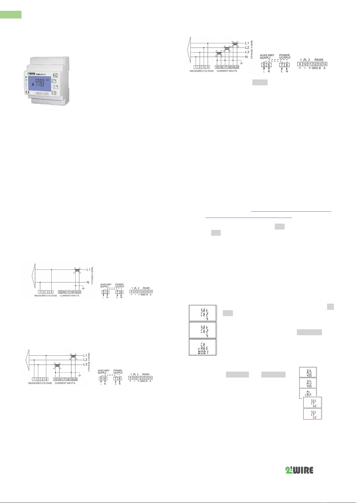
EMM.630 (M)CT: Mono-phase connection
On display: set as mono phase: SYS 1P2
Reference voltage: Neuter on Clamp 1; Phase on Clip 4
Flow coil: Keep flow arrow on coil, arrow points to Users! Black
conductor(=GND) on Clip 19; White conductor on Clip 20
Power voltage module: Neuter on Clamp 6,Phase on Clamp 5
Note: by-loop-Clamp to next meter Clamp 7= Clamp 5; Clip 8= Clamp6
Modbus connections: Clamp A (=13) and B (=14) and GROUND (=12 GND)
EMM.630 CT: 3x230V connection
On display: set as 3phase/3guider: SYS 3P3
Reference voltage: L1 on Clamp 4; L2 on Clamp 1; L3 on Clip 2
Flow coil: Keep current arrow on coil, arrow points to consumer!
Rinse L1: Black conductor (=GND) clamp 19; White conductor clamp 20
Rinse L2: Flow I2 (I1+I2+I3=0) is calculated, so does not need to be
measured and therefore no coil required! For this reason, no power is
logged in the Memo for this phase2.
Rinse L3:Black conductor (=GND) on clip 15; White conductor on clamp 16
Power supply voltage: Neuter on Clamp 6; Phase on Clip 5
Note : by-loop-Clamp to next meter:Clamp7= Clamp 5; Clip 8= Clamp6
Modbus connection: Clamp A (=14) and B (=13) and GROUND (=12 GND)
EMM.630 CT: 3x380V+N connection
On display: set as 3phase/3guider: SYS 3P4
Reference voltage: L1 on Clamp 4;; L2 on Clamp 3; L3 on Clamp 2;
N=Clamp 1
Flow coil: Keep current arrow on coil, arrow points to consumer!
Rinse L1: Black conductor (=GND) on Clip 19; White conductor on Clip 20
Rinse L2: Black conductor (=GND) on Clip 17; White conductor on Clip 18
Rinse L3: Black conductor (=GND) on Clip 15; White conductor on Clip 16
Power voltage module: Neuter on Clamp 6; Phase on Clip 5
Note: Loop-Clip to Next Meter Clip 7= Clip 5; Clip 8= Clamp6
Modbus connection: Clamp A (=14) and B (=13) and GROUND (=12 GND)
2: Configuration on the display:
This module is partly pre-configured and only needs to be entered:
a UNIQUE Modbus address, number between 1... 247
the type of power supply mono,3x230V,3x380V+N, standard at
3x380+N
the type of coil: be careful, this can only be done once and cannot
be adjusted afterwards!!!
How to get into SETUP:
(watch video tutorial) https://www.2-wire.net/en/product/3f-
energy-meter-ct-mid-modbus-emm-630-ct/)
Push the bottom button 4 (enter→)until PASS 0000 appears, fill in default
password PAS 1000 by pressing the button 2 (M↑) to 1, briefly press button
4 (enter) for next number or press enter for a long time to move to next
setting. Go through button 3 (P√) through the set values and adjust the
necessary Modbus values. Briefly press button 1 (U/I ←)) to leave menu.
Modbus parameters to be set: 9600 8N1
Modbus address : Id001... Id247
Baudrate: b 9600
Parity: Prty n (parity none)
Data: 8 bit
Stopbit: 1
Secondary current of the coil 1Ampere or 5Ampere: SET
Ct2 5 At the EMM.630CT-MID this can only be set
once!!
Multiplication factor = primary/ to secondary flow
strength of the coil, E.g. 100A/5A=20: Ct rATE 0020
With the EMM.630CT-MID this can only be set once!
In case Rogowski: CT1 should be set to 1kA, in the
EMM.630 MCT-RC meter you can still change settings
afterwards
ATTENTION:
1. The values SET Pt2 400 and Pt rAtE 0001 are
for high voltage and can only be adjusted once.
Leave it on DEFAULT! !
2. The backlight of the display can be set to
0/5/10/30/60/120.
0 stands for continuous, 5/10/30/60/120
means switch off after the set period . Here
better choose 5/10/30 to increase the service
life.
3: Configuration in the web server
In the web server, go to /configuration/modules:

Qonnex
18
Quick start 2-Wire v3.0
1. Enter unique fictitious serial number starting with 03E followed
by a unique number with 5 digits: Vb.. 03E00002
2. Give a name to the meter: Vb.. EMM.630CT and press "NEW"
3. A table appears with 3 rows, 1 row per stage. Give a recognizable
name to the each stage exit: Vb.. Phase 1, Phase 2, Phase 3
4. Choose mode COUNTER(automatic)
5. Enter the Modbus address of the module: Vb.. 17 (AND NOT
017!!)
6. Enter Modbus sub-address : always 0 (phase 1); always 1 (phase
2); always 2 (phase 3);
7. Log type: Only if you're working on charging data to a central
server check the parameters you want
8. Choose unit kWh(automatic)
9. Press "ZEND" if Module OK appears the programming is in order
otherwise Module NOK see manual (Modbus address error,
cabling check,...)
4. Read values on the display
There are 4 touch buttons by pushing on this momentarily you can read the
following readings:
Button1 U/I (voltage/currents): voltages between phase Neuter Volt→ flow
per phase in Ampere→ Harmonic on voltage between phase and neuter THD
in %→ Harmonic on current THD in %→
Button 2 M (frequency, PF, peak): frequency and power factor→ power
factor per phase → maximum flow per phase with set sample me aer
reset→ maximum total power set sample me aer reset Button
3 P (capabilities): current active power per phase in kW→ current reacve
power per phase in kVar→ current VA per phase in kVA→ total power in kW,
KVar, kVA
Button 4 E (energy consumption meter reading)*: meter reading total
active consumption in kWh→ meter posion total reacve consumpon in
kVarh→ meter posion import acve consumpon in kWh → meter posion
export active consumption in kW → meter posion import acve
consumption in kVarh → meter state export acve consumpon in kVarh →
*beware meter reading on 2 lines as 1 line: 0001 04.80 kWh=104.80kWh
5. What values are logged.
MEMo logs every 60 seconds:
Total active consumption over the 3 phases:
o Meter mode import in kWh
o Meter mode export in kWh
By phase:
o Tension in Volt
o Power in Ampère
o Power in Watt
o Power factor
o Reactive capability VAR
6. General note:
Import consumption over the 3 phases, in the html chart only with
1 hour resolution, is calculated on the basis of difference between
start and end counter position and the result you see in the web
server below the chart of phase 1 (Modbus sub-address0). Export
consumption can be found in the web server under phase 2
(Modbus sub-address 1),see FAQ on 2-wire.be
The current counter positions import and export can be read in
the web server (light green values) by pressing 'AUTO REFRESH'.
Via button E on the display is ToTal Energy = Import +Export in
kWh
3x380V NEUTERLESS: connect as 3x230V and set as 3P3
Visualization of the channels for the customer : see WS.502 web
server
Because the web server cannot show
negative graphs, the Energy meter for solar
panels must be connected in the direction of
the current.
If current power is at 0 in the web server
then check flow direction coils via display
Rinsing flow direction is wrong if PF or power
on the display is negative, Never swap wires
from coils around current feeder but open and
turn the coil to avoid power surge!!!
In the case of 3x230Volt, current power Phase 2 is always shown
as zero in the web server because this calculated power is
negative and the web server does not show any negative values.
Flow-rinse guides may be extended a few meters but with at least
the same section
The comprehensive (English) manual with all technical
specifications, detailed configuration, Modbus registers is
available through our website www.2-wire.net
7. Installation instructions
The installation must be carried out by an approved installer and in
accordance with the rules in force.
This device is only suitable for DIN rail assembly in accordance
with EN 50022 and must be fitted in a closed distribution
board.
Make sure that a safety interruption of the device is possible.
Turn off the module before installing it.
Do not open the device – the warranty expires when the
device is opened.
This manual must be attached to the file of the electrical installation. The
2-Wire website always has the latest manual of the product.
8. Support
Do you want to exchange the product in case of a possible defect? Please
contact your wholesaler or the 2-wire support service. The contact details
can be found on our website www.2-wire.net/contact/
9. Guarantee conditions
The warranty period is two years from delivery date. The date of delivery
is the invoice date of purchase of the product by the consumer. If there is
no invoice available, the production date applies.
The consumer is obliged to inform Qonnex bvba in writing of the lack of
conformity, and this at the latest within two months of adoption. In the
event of a lack of conformity, the consumer is only entitled to a free
repair or replacement of the product, which is determined by Qonnex.
Qonnex is not responsible for any defect or damage caused by improper
installation, improper or negligent use, improper operation, product
transformation, maintenance in violation of maintenance regulations or
an external cause such as moisture damage or damage from span.
The mandatory provisions in national legislation on the sale of consumer
goods and the protection of consumers in countries where Qonnex sells
directly or through distributors, agents or permanent representatives take
precedence over the above provisions
Qonnex
B-9310 Aalst
Belgium
www.2-wire.net
This manual suits for next models
2
Other Qonnex Measuring Instrument manuals
Popular Measuring Instrument manuals by other brands

Precision Digital Corporation
Precision Digital Corporation Loop Leader PD6600 Series instruction manual

Shell
Shell Energy SMETS1 manual

Wandel & Goltermann
Wandel & Goltermann OLP-10 Service manual

Hitachi
Hitachi U-2810 instruction manual

MULTI MEASURING INSTRUMENTS
MULTI MEASURING INSTRUMENTS MLD-18 instruction manual

Agilent Technologies
Agilent Technologies NFA Series Setup guide