manuals.online logo
Brands
  1. Home
  2. •
  3. Brands
  4. •
  5. Kele
  6. •
  7. Accessories
  8. •
  9. Kele LX-24 User manual

Kele LX-24 User manual

CAUTION
When working on or near high voltage, use proper safety precautions.
LED does not flash with motion:
1. Determine if the lens is masked in the direction being tested (see masking).
2. Check that the sensitivity setting is set to maximum (DIP switch #3 to ON)
3. Check that the red and black wire connections from sensor are secure.
4. Check that 24VAC or 24VDC is between the red and black wire from
the sensor.
•If it is present, the problem may be with the sensor, try another sensor
(if available).
Isolated relay not functioning properly:
1. Check that time delay setting are correct (DIP switch #1 and #2);
2. Check sensitivity setting. For unwanted sensor activations, see below.
3. Check that all wire connections from sensor are correct and secure.
4. Using proper precautions, check that there is voltage to the isolated relay.
5. Check that 24 VAC or 24 VDC is between the red and black wire
from the sensor.
6. Use an ohmmeter to check the function of the isolated relay;
•Turn off the power connected to the isolated relay wires (if applicable)
— With motion in front of the sensor’s lens, check that the connection
between the green and orange wires is open.
— With motion in front of the sensor’s lens, check that the connection
between the yellow and orange wires is closed.
•Turn sensitivity and time delay to minimum, cover the sensor’s lens with a
cloth (not your hand), be still and allow the sensor to time-out.
— Check that the connection between the green and orange wires is closed.
— Check that the connection between the yellow and orange wires is open
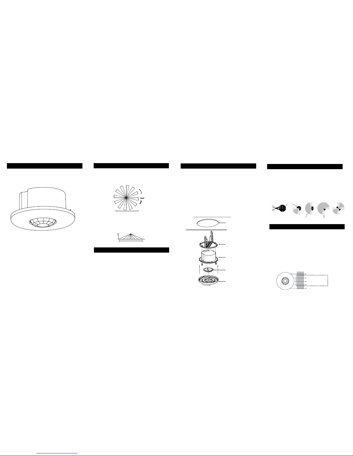
Sensor Override:
LX-24
Installation Instructions
360º PIR Occupancy Sensor
TROUBLESHOOTING
3000 Brother Blvd
Memphis, TN 38133
kele.com • 888-397-4923 US • 901-382-6084
Unwanted Sensor Activations (LED flashes):
Possible causes Possible solutions
1. People moving or walking outside
of the desired coverage area, but
in view of the sensor and within its
range (see coverage patterns and
placement)
Mask the lens to reduce PIR coverage
(see “masking the lens”)
Setting the sensitivity to minimum
if necessary (DIP switch #3)
2. Sensor located too close to vents
with heavy air flow
Relocate the sensor
The sensor comes factory preset and ready for operation.
If testing of operation is desired:
• Remove the sensor’s cover (twist);
• Refer to the DIP switch settings chart below for switch configurations;
1. Confirm the override DIP switch is set to normal (DIP switch #4 to OFF);
2. Restore power and turn on the system interfacing with the isolated relay.
There is a one minute warm-up when power is initially restored to the
sensor before the sensor works properly.
3. Set time delay to minimum: DIP switches #1 and #2 to OFF (30 seconds).
4. Set sensitivity to maximum: DIP switch #3 to ON.
5. Replace the sensor’s cover;
6. Move away from sensor and be still. The sensor should time-out after
30 seconds and the isolated relay contacts should return to their
“normal” condition (normally open or closed, see wiring directions
diagram). Note: If the sensor does not time-out or the isolated relay does
not return to its normal condition, move farther away or out of sight of
the sensor, or see Unwanted Sensor Activations under troubleshooting.
7. Reset the time delay to the desired delay (DIP switch #1 and #2).
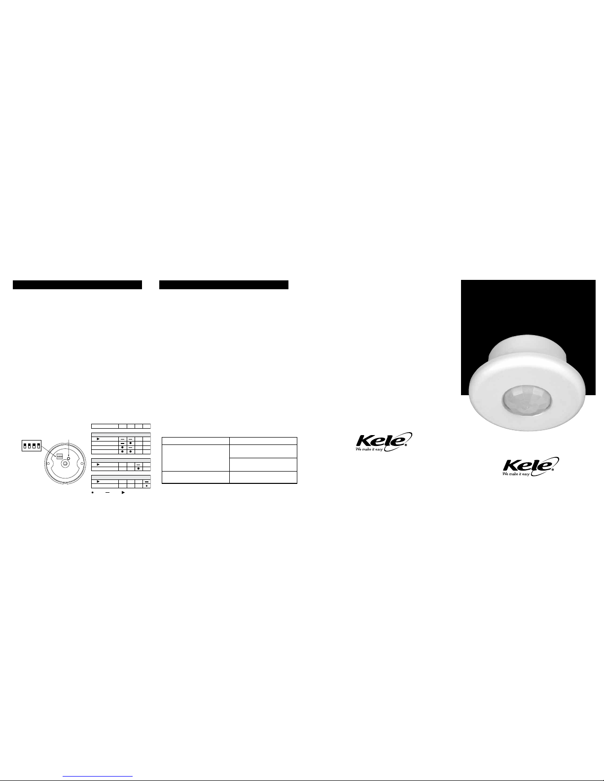
SENSOR ADJUSTMENT
DIP SWITCH SETTING
Your ultimate choice in BAS selection,
service, and technical support.
DIP switch # 1 2 3 4
Time delays
30 seconds
10 minutes
20 minutes
30 minutes
Sensitivity
Minimum
Maximum
Override
Normal
Override
= On = Off = Factory preset
4321
ON
4
321
ON
DIP switch control
for time delay,
sensitivity and
override
LED
If the sensor fails, set DIP switch #4 to override position (DIP switch #4 to on).
This overrides the sensor and sets the circuit to “on”.
The LX-24 is a 24 VAC or 24 VDC Passive Infrared (PIR) occupancy
sensor. The LX-24 provides isolated relay contacts that are normally
open or normally closed. This PIR-type sensor can integrate with HVAC
or EMS systems.
The LX-24 passive sensing system reacts to changes in infrared
energy (moving body heat) within the coverage area. Sensor placement is
important with PIR sensors; the sensor must directly “see” motion
of an occupant in order for detection to occur.
The effective coverage distances may be slightly less than the maximum
sensing distance, depending upon obstacles such as furniture or
partitions, and this must be considered when planning the number
of sensors and their positioning.
The LX-24 sensor can be mounted at various heights. Mounting heights of
less than 8 feet decrease the range and increase the sensitivity to smaller
motions. Conversely, mounting heights greater than 8 feet increase the
range and decrease the sensitivity to smaller motions. At heights greater
than 12-14 feet, you risk reduced sensitivity.
1. If using the ceiling attachment ring, bend the securing straps up so
the sensor housing can be inserted, and attach it to the sensor with
the provided screws
2. Attach the mask, if using, into the lens recess and onto the securing
pins of the cover.
3. Attach the cover to the rear housing; align tabs on inside of cover
to notches on outside perimeter of rear housing, place cover on
sensor, and twist clockwise to lock.
4. Insert the assembled sensor into the ceiling hole, and if using
the mask turn the sensor so that the unmasked part of the lens is
toward and centered on the area to be covered.
5. Bend the ceiling attachment ring straps behind the hole to secure.
CAUTION:
TURN POWER OFF AT CIRCUIT BREAKER BEFORE WIRING SENSOR.
• Connect 24 VAC or +24 VDC supply to the Red and return to the Black
wire from the sensor.
Isolated relay (Rated for 1A@24 VDC or 24 VAC)
Connect the wires necessary to the application that requires this output.
• Green (normally closed)  open when occupancy is detected
• Orange (common) must be used for proper operation
• Yellow (normally open) closed when occupancy is detected.
Cover (with lens)
Mask (optional)
(Cut for desired coverage)
Rear housing
Ceiling attachment ring
(bend behind ceiling to secure)
3" Hole
Ceiling
Top View
Side View
360°
2.5m
Low sensitivity
High sensitivity
8m Max.
8m Max.
Mask
Cut mask into sections
for desired coverage,
shown right. Coverage area Reduced sensitivity
It has a fresnel lens eld of view of 360°. Coverage shown in the
diagram below is maximum and represents coverage for half-step,
walking motion, with no barriers or obstacles.
COVERAGE PATTERNS
DESCRIPTION
PLACEMENT
WIRING DIRECTIONS
MASKING
INSTALLATION
An insert mask is supplied to allow elimination of coverage in unwanted
spaces. The mask is cut as needed and mounted onto anchor pins in the
sensor’s cover.
Important: For full coverage, no mask is needed.
Important: The assembled sensor must be turned so the unmasked
portion of the lens faces the coverage area prior to securing sensor to
mounting location.
Note: There is a small area of reduced sensitivity
corresponding to the lighter areas in the examples below.
Red 24 VAC or +24 VDC
24 VAC or 24 VDC return
Normally closed contact Isolated
Relay
Output
Normally open contact
Common
Green
Orange
Yellow
Black
Top View
Side View
360°
2.5m
Low sensitivity
High sensitivity
8m Max.
8m Max.

Other Kele Accessories manuals

Kele KCO-NO2 User manual

Kele

Kele KCO-NO2 User manual

Kele K-02 User manual

Kele

Kele K-02 User manual

Popular Accessories manuals by other brands

Duomo CO200 manual

Duomo

Duomo CO200 manual

Chacon 84164 quick start guide

Chacon

Chacon 84164 quick start guide

Saimo 6105 Installation, operating and service manual

Saimo

Saimo 6105 Installation, operating and service manual

MaiJia Intelligent Technology MJ-VU01 manual

MaiJia Intelligent Technology

MaiJia Intelligent Technology MJ-VU01 manual

WebEye RoadPass OBU user manual

WebEye

WebEye RoadPass OBU user manual

Viking DDWB301CRSS installation instructions

Viking

Viking DDWB301CRSS installation instructions

blindsgalore SOLANA installation instructions

blindsgalore

blindsgalore SOLANA installation instructions

Elko Inels AirQS-101S manual

Elko

Elko Inels AirQS-101S manual

MOB MO8640 user manual

MOB

MOB MO8640 user manual

Purebits X2 owner's manual

Purebits

Purebits X2 owner's manual

Alarm Controls Corporation SREX-100 operating instructions

Alarm Controls Corporation

Alarm Controls Corporation SREX-100 operating instructions

WallSenzr LBS-700 Series installation instructions

WallSenzr

WallSenzr LBS-700 Series installation instructions

NEW BRUNSWICK SCIENTIFIC CO28IR Guide to Operation

NEW BRUNSWICK SCIENTIFIC

NEW BRUNSWICK SCIENTIFIC CO28IR Guide to Operation

Gesslein F Series operating instructions

Gesslein

Gesslein F Series operating instructions

American Standard 18" Towel Bar 7010.180 installation instructions

American Standard

American Standard 18" Towel Bar 7010.180 installation instructions

Tranberg TEF 1536 user manual

Tranberg

Tranberg TEF 1536 user manual

JANE micro-pro instructions

JANE

JANE micro-pro instructions

YATEK EL06000 user manual

YATEK

YATEK EL06000 user manual

manuals.online logo
manuals.online logoBrands
  • About & Mission
  • Contact us
  • Privacy Policy
  • Terms and Conditions

Copyright 2025 Manuals.Online. All Rights Reserved.