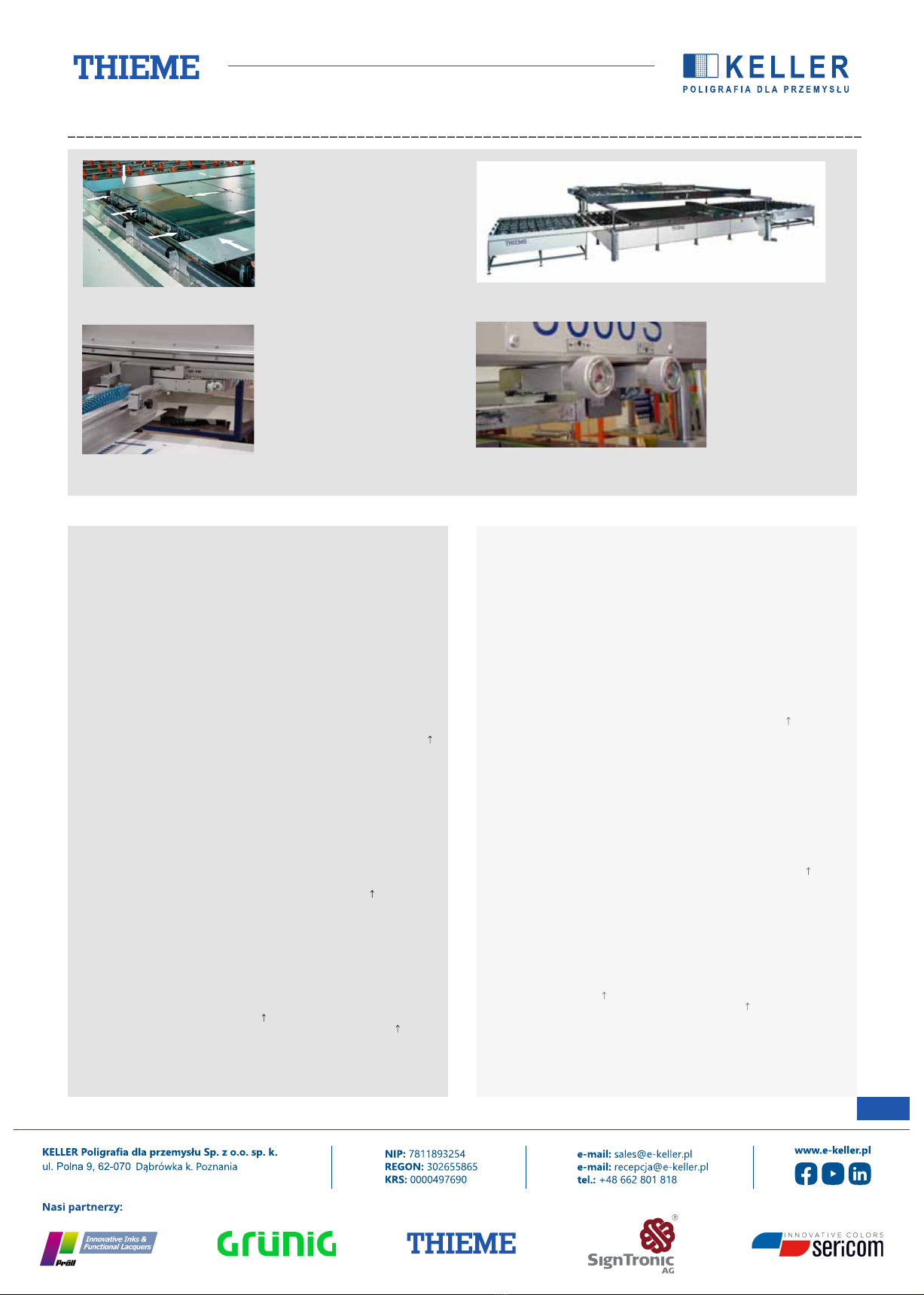
NAPĘD ZESPOŁU RAKLA
Wytrzymały, bezobsługowy trójfazowy motoreduktor przekazuje
napęd na wałek synchronizujący za pomocą łańcucha. Liniowy ruch
zespołu rakla odbywa się za pośrednictwem paska zębatego bez
drgań i przy minimalnym zużyciu; prowadnica wózka rakla jest w
całości zabudowana.
Regulator częstotliwości z programowalnymi rampami
przyspieszenia i hamowania umożliwia wzajemnie niezależną,
bezstopniową regulację prędkości rakla i przedrakla (zgarniacza).
Żądane prędkości ustawia się za pomocą klawiatury przy panelu
sterowania i są one wskazane w postaci cyfrowej.
ODSTĘP OD FORMY SITODRUKU
Odstęp od formy sitodruku można ustawić bezstopniowo w
zakresie od 8 do 45 mm i zaprogramować za pomocą panelu
sterowania dla różnych wartości napięcia sita i grubości materiału.
PROGRAMOWANIE DROGI POSUWU RAKLA
Przednie oraz tylne położenie krańcowe zespołu rakla wprowadza
się z dokładnością do milimetra za pomocą klawiatury bądź
wskazuje bezpośrednio w programie poprzez funkcję Teach-In i
zapisuje. W obu przypadkach na wyświetlaczu wskazywane są
dokładnie ustawione wartości. Dzięki temu droga posuwu rakla
przy określonej wielkości sita, czy też drukowanego obrazu, staje
się powtarzalna. Nie jest już potrzebna czasochłonna procedura
regulacji drogi posuwu rakla za pomocą wyłączników krańcowych.
Ponadto zespół rakla osiąga zaprogramowane położenia krańcowe
również w przypadku zmiany prędkości posuwu rakla lub
przedrakla. Nie jest konieczna ponowna regulacja, co pozwala
uniknąć niepotrzebnego czasu przestojów produkcyjnych.
Programowanie poprawia bezpieczeństwo i ergonomię
użytkowania. Przypadkowe przestawienie któregokolwiek z
wyłączników krańcowych nie spowoduje kolizji rakla z ramą
maszyny, a więc w szczególności nie będzie z tego powodu
konieczny przestój maszyny i przeprowadzenie naprawy.
PRĘDKOŚĆ POSUWU RAKLA I PRZEDRAKLA
Zespół napędowy składa się z wytrzymałego trójfazowego
motoreduktora przekazującego napęd z udziałem regulatora
częstotliwości na pasek zębaty.
Prędkość posuwu rakla i przedrakla można ustawić niezależnie od
siebie w mm/s za pomocą klawiatury. Ze względu na ogromny
wpływ prędkości posuwu rakla na rezultat pracy wskazanie
zadanych ustawień staje się zaletą. Zmiana prędkości rakla bądź
przedrakla nie ma wpływu na drogę posuwu rakla.
LICZNIK SZTUK I LICZNIK GODZIN PRACY
Włączany i wyłączany licznik sztuk wskazuje liczbę cykli
wykonanych przez maszynę. W trybie automatycznym można
zaprogramować dowolną liczbę sztuk. Niezwłocznie po osiągnięciu
żądanej liczby sztuk sterownik zatrzymuje tryb automatyczny.
Licznik godzin pracy w połączeniu z licznikiem sztuk pozwala
kontrolować wydajność osiąganą przez maszynę i pomaga
przestrzegać okresów konserwacji.
6
OPIS URZĄDZENIA / MACHINE DESCRIPTION - THIEME 3000 GS LS
SQUEEGEE ASSEMBLY MOTOR
A sturdy, maintenance-free three-phase current motor drives the
synchronizing shaft via a chain. The linear motion of the squeegee
assembly by means of toothed belts is absolutely free from
vibration and resistant to wear. The squeegee carriage guide is
enclosed.
A frequency regulator with programmable acceleration and
deceleration ramp allows the velocity of the squeegee and flood bar
to be continuously adjusted independently of each other. The
velocities are programmed at the control panel via the keyboard
and displayed in numeric form.
OFF-CONTACT
The off-contact can be continuously adjusted and program- med at
the control panel to any value between 8 and 45 mm to match
screen tension and material thickness.
PROGRAMMING SQUEEGEE STROKE
The final front or rear position of the squeegee assembly is either
entered via the keyboard, or the squeegee assembly is moved to
the appropriate position and saved through “teach-in”. In both
cases, the display will accurately indicate the set values. Thus, the
squeegee stroke for a given screen
or stencil size has become reproducible. The time-consuming
procedure of adjusting the squeegee stroke by means of limit
switches can thus be eliminated.
In addition, the squeegee assembly will always travel to the exact,
programmed end positions even when the squeegee or flood bar
velocity has been changed. No tedious readjustments are required.
Programming is as simple as it is safe. There is no risk of mis-
adjusting a limit switch, causing a collision of the squeegee with
the machine frame, repair costs and down times.
SQUEEGEE AND FLOODBAR VELOCITY
The drive unit is a sturdy, three-phase current, geared motor that
is frequency-controlled, acting on the toothed belts.
Squeegee and flood-bar velocities are entered separately in
mm/second via the keyboard. The important impact that the
squeegee velocity has on the print result makes the information
about the set value an asset. Changing the squeegee or flood-bar
velocity will not affect the programmed squeegee stroke.
SHEET COUNTER AND OPERATING HOURS COUNTER
The sheet counter can be enabled and disabled; it counts the print
cycles performed. For automatic printing, any number of sheets to
print can be entered. As soon as this number is reached, the
automatic print mode will be interrupted.
In conjunction with the sheet counter, the operating hours counter
is an indicator of the machine output and helps observe the service
interv2als.