– 36 –
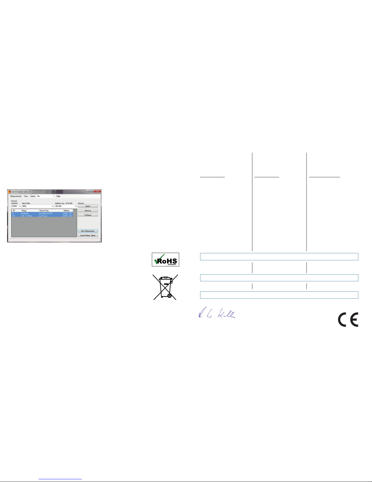
Recording K-114 BT measurements
The measurements I-OUT, U-IN, U-OUT and U-BAT can be recorded and stored via the software ControlCenter-
Series30 (CCS30). Read the CCS30 manual to nd out more about this.
In order to display the data for the K-114 controller using the software, you must enter bus address 253 in CCS30
and start the search for the device. You can display and store measurements via the „New measurement“ function.
RoHS
This product complies with EC Directive 2002/95/EC on the restriction of the use of certain
hazardous substances in electrical and electronic equipment.
Disposal
The product must not be disposed of with ordinary domestic waste at the end of its service
life. To prevent any damage to health or the environment caused by improper disposal, this
product must be separated from other waste and properly recycled in order to ensure that the
raw materials are processed sustainably.
Konformitätserklärung
Für das folgende Erzeugnis wird hiermit
bestätigt,
Konverter K-114 BT
dass es den wesentlichen Schutzan-
forderungen entspricht, die in der Richt-
linie des Rates zur Angleichung der
Rechtsvorschriften der Mitgliedstaaten
über die elektromagnetische Verträglich-
keit (2004/108/EG) festgelegt sind.
Diese Erklärung gilt für Produkte dieser
Serie, die mit dem CE-Zeichen ver-
sehen und die Bestandteil dieser Erklä-
rung sind.
Zur Beurteilung der Erzeugnisse hin-
sichtlich elektromagnetischer Verträg-
lichkeit wurde folgende Normen heran-
gezogen.
Jestetten, 26. Mai |May |mai 2016
Hannes W. Keller – Geschäftsführender Inhaber |Managing Owner |Président Directeur Général
mit rechtsgültiger Unterschrift |with legally effective signature |dûment autorisé à signer
Declaration of Conformity
Herewith we declare, that the following
products or product range
Converter K-114 BT
meet the basic requirements for the
electromagnetic compatibility, which
are established in the directive of the
European Community (2004/108/EC).
This declaration is valid for products of
this Series marked with the CE sign and
which are part of this declaration.
As criteria for the electromagnetic com-
patibility, the following norm is applied:
Déclaration de Conformité
Nous attestons que les produits ou
gammes de produits :
Convertisseurs K-114 BT
répondent aux exigences de base en
matière de compatibilité électromagné-
tique prévues par la directive de la
Communauté Européenne (2004/108/
CE).
La présente déclaration est valable
pour les produits de cette série, mar-
qués avec le sigle CE et faisant partie
intégrante de la présente déclaration.
La norme appliquée pour évaluer la
compatibilité électromagnétique desdits
instruments est la suivante :
EN 61326-1:2013
Diese Erklärung wird verantwortlich für
den Hersteller:
This declaration is given for the manu-
facturer
La présente déclaration est fournie
pour le fabricant
KELLER AG für Druckmesstechnik, St. Gallerstrasse 119, CH-8404 Winterthur
abgegeben durch die in full responsibility by par
KELLER GmbH, Schwarzwaldstrasse 17, D-79798 Jestetten