Keller HTP1 User manual

21
Hydraulic Hand Pump HTP1

22
About this operating manual 23
1 Device description 24
1.1 Intended use 25
1.2 Exclusion of liability 25
2 Safety instructions 26
3 Construction and function 27
3.1 Importantnotesonpressureuctuations 28
4 Purging hydraulic lines 29
5 Handling 30
5.1 Generating pressure 31
5.2 Pressure measurements 33
5.3 Releasing pressure 34
6 Problems 35
7 Maintenance / cleaning, storage and transportation 36
8 Disposal 37
9 Technical data 38
Contents

23
● Theoperatingmanualisaimedatspecialistsandsemi-skilledpersonnel.
● Beforeeachstep,readthroughtherelevantadvicecarefullyandkeeptothespe-
ciedorder.
● Thoroughlyreadandunderstandtheinformationinthesection“Safetyinstructions”.
If you have any problems or questions, please contact your supplier or contact us
directly at:
KELLER AG für Druckmesstechnik
St. Gallerstrasse 119
CH-8404 Winterthur
+41 52 235 25 25
www.keller-druck.com
About this operating manual

24
The hand pump creates positive pressure
fortheinspection,adjustmentorcalibration
of all kinds of pressure-measuring devices.
The lightweight, compact design makes this
handpump ideal for on-site testing.
The hand pump and the pressure hose have
Minimess®connections. When the hand
pump is used, it needs to be connected to a
reference gauge and to the test item.
Scope of delivery
Check the delivered items:
âHand pump
âPressure hose
âOperation manual
âAccessories
Transportation cases, Minimess®-adapter,
adapter sets and seal sets are optional ac-
cessories.
● Transportationcase:
The transportation case provides optimal
protection for the hand pump and other
accessories with its tight-tting rigid
foam inlay. A document compartment is
located in the lid behind the burl foam
inlay.
● Minimess®Adapter
● Fillingbottle
● Adapterset:
The adapter set comprises 7 adapters for all common pressure connections with or
without pins.
●
Sealset:ThesealsetcontainsatsealsmadeofplasticandO-ringsforallcommon
pressure connections.
Reference gauge
VariousreferencemodelsfromKELLER’sproductrangecanbeused.
1 Device description
Pressure hose
Hand pump
Reference Gauge
Hydraulische Handpumpe HTP1
Hydraulic Hand Pump HTP1 Page21
Pompe hydraulique manuelle HTP1 Page41
03/2017

25
1.1 Intended use
The HTP1 hand pump can only be used for generating pressure in low-volume
measuring devices. The device is only designed for use with hydraulic oil or deminera-
lized water, other media will result in damage to the hand pump.
The hand pump may not be attached to external pressure sources.
WARNING! No safety component!
The hand pump of the series HTP1 is not safety component in accordance with Direc-
tive 2006-42-EC (Machine Directive).
âNever use the HTP1 as a safety component.
The operational safety of the device supplied is only guaranteed by intended use. Do
NOTexceedthespeciedlimits(➝paragraph9:“Technicaldata”).
CAUTION! Risk of injury or material damage!
By connecting the HTP1, the measuring device is hydraulically connected to the
handpump.Ifthepressurereliefvalveisopened,acompressedmediumcanow
throughthepressurehoseintothehandpump’sstoragecontainer.Atsufcientlylarge
volumes,thereservoirmayoverow.
âNever connect the HTP1 directly to the hydraulic system with large volumes
(constructionmachines,etc.)oranaggressivemedium(suchasbrakeuid).
Before ordering and installation, check that the hand pump is suitable for your appli-
cations.
1.2 Exclusion of liability
We accept no liability for any damage or malfunctions resulting from incorrect in-
stallation, in-appropriate use of the device or failure to follow the instructions in this
operating manual.
1 Device description

26
Before you install the HTP1, read through this operating manual carefully. If the
instructions contained within it are not followed, especially the safety guidelines, this
could result in danger for people, the environment, and the device and the system it
is connected to.
The HTP1 corresponds with state-of-the-art technology. This concerns the accuracy,
the operating mode and the safe operation of the device.
In order to guarantee that the device operates safely, the operator must act compe-
tently and be conscious of safety issues.
KELLER provides support for the use of its products either personally or via relevant
literature. The customer assumes responsibility for any testing to determine applica-
tion suitablility. KELLER is not reponsible for damages due to misuse or application
incompatability.
Qualied personnel
● ThepersonnelwhoarechargedfortheinstallationandoperationoftheHTP1must
holdarelevantqualication.Thiscanbebasedontrainingorrelevantexperience.
The personnel must be aware of this operating manual and have access to it at all
times.
General safety instructions
●
In all work, the existing national regulations for accident prevention and safety in the
workplace must be complied with. Any internal regulations of the operator must also
be complied with, even if these are not mentioned in this manual.
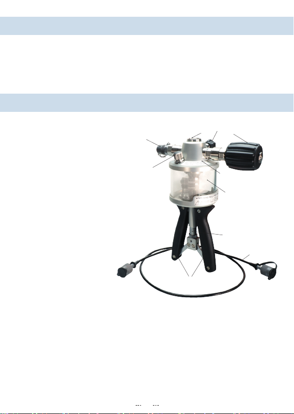
● Neverusethehandpumptogetherwithanexternalpressuresource.Donotattach
an external pressure generator to the hand pump.
● Donotusebrakeuidorotheraggressivemedia.
●
Do not remove any attached components (test item, pressure hose, reference gauge)
when the hand pump is under pressure:
– Open the pressure relief valve before removing any of the components.
–DonotuseTeontapetosealthepressureconnections.SurplusTeontapecan
enter the hand pump and damage it.
– Only use adapters and seals that are available as accessories.
– Non-pressurised storage: Only store the hand pump with the pressure relief valve
open. This ensures that no pressure can be built up by unintentional pumping
movements.
– Avoid external force of all kinds towards the hand pump and its operating
elements.
– Do not use the hand pump if it is damaged or defective.
2 Safety instructions

27
Special safety instructions
Warningsthatarespecicallyrelevanttoindividualoperatingproceduresoractivities
can be found at the beginning of the relevant sections of this operating manual.
Connections
➀Minimess® connection
pressure hose
➁Connector reference gauge
Operating elements
➂Fineadjustmentvalve(handwheel)
➃Pressure relief valve (rotary knob)
➄Seal reservoir with safety valve
➅Hand grips
Main components
➆Upperandlowerpumpbody
➇Reservoir with suction and
relief outlets
➈Piston rod with
internal spring
➉Pressure hose with
Minimess®connection
Function
Thereferenceandthetestsampleorthepressuredevicetobetested(hereafter“test
sample”)areconnectedtothehandpump.
Pumping is carried out by repeatedly pushing the hand grips together. An internal
spring returns the hand grips to their start position.
The pumping movements are transferred to the pistons in the pump body via the push
rods. The hydraulic liquid is then suctioned from the storage container and pressed
through valves to the test item.
2 Safety instructions
3 Construction and function
➀➁➂
➃
➄
➅
➆
➇
➈
➉
➆
➀➀

28
When properly purged, the hand pump will generate positive pressure quickly. The
construction of the hand pump means that the same pressure is generated for the test
item as for the reference test gauge.
Thepressureissettothenecessaryvalueusingtheneadjustmentvalve.Withthe
pressure relief valve, the pressure can be relieved into the reservoir.
For the assessment of the test sample, the pressure displayed on the reference
manometer is compared with the measurement value.
3.1Importantnotesonpressureuctuations
It is completely normal that the pressure is not constant from the start. In the event
of changes to the pressure in the measurement device, it always lasts a few minutes
until the pressure stabilises.
Thisisinuencedbyavarietyoffactors.Themostimportantinuencefactorsare:
● Improperpurging:
If there is still air in the measurement device, the pressure build-up lasts signi-
cantlylonger.Moreover,thereisafall-offinpressureoveralimitedperioddueto
diffusion processes.
● Mechanicalcharacteristicsofthepressurehose:
Bending or rolling up the pressure hose causes a reduction in the volume and thus
leads to an increase in pressure.
At high pressure, the pressure hose extends. Furthermore, enclosed air can be
diffused through the pressure hose. In both cases, a drop in pressure results.
● Temperatureinuence:
Temperature changes lead to a change in volume in the measurement device and
therefore to changes in pressure. The smaller the volume is, the greater the change
in pressure.
● Settlingtimesofreferenceandtestsample:
Observe the required waiting times after the reference and test sample have been
switched on. More information on this can be found in the corresponding operating
manual.
3 Construction and function

29
In order for the hand pump to be operated, it is vital that its connections with the refe-
rence gauge and the test item are pressure-resistant.
Furthermore, for the best measurement procedure possible, sufcient and correct
purging of the measurement device is required. Only then can you reduce the pres-
sureuctuation(➝paragraph 3.1) to a minimum.
CAUTION! Material damage!
The test sample, the adapter and the seal must be free from impurities to prevent
damage to the hand pump or hydraulic lines.
Maximum torque of the pressure connections:
Reference: 15 Nm
Test item: 15 Nm
Carry out the following steps* for the purging air from the hydraulic lines of the hand
pump.Forthis,notealsothewarningsinsectionparagraph5.1“Generatingpressure”.
â
Fill the storage container to approximately two-thirds capacity with the required
hydraulicuid.
âOpen the pressure relief valve by turning counter clockwise.
âTurnthereferencemanometerwithmatchingsealinthehandpump’sconnection
(G1/4).
IMPORTANT! Do not tighten the reference yet!
âCarefully pump until the hydraulic liquid escapes at the connection and the piston
system has been ventilated.
âOnly then should you tighten the reference.
âPump 5…10 times to prime the hydraulic lines.
âTurnthepressurereliefvalvecounterclockwiseuntilitisrmlyclosedt.
âConnect the pressure hose to the hand pump’s Minimess®connection, and
tighten the connection.
âTightly screw the Minimess®adapter on the pressure hose.
âSelectthesuitableadaptersandsealsforthetestitem’sconnection.
âScrew the adapter for the test sample onto the Minimess®adapter.
âTurn the test sample with seal in the adapter.
IMPORTANT! Do not yet tighten the test item!
âNowpumpuntilthehydraulicliquidescapesatthetestsample’sconnection.The
pressure hose and the test sample connection are now ventilated.
4 Purging hydraulic lines

30
CAUTION! Demineralized water!
During the quality inspection of the HTP1, a functional test is carried out with demine-
ralised water. The reservoir may therefore contain residues of this liquid.
âCheck the compatibility with your application and remove the residue using appro-
priate measures (e.g. rinsing out with the hydraulic liquid).
* Therststepsupto“Tighteningofthereference”areonlyrequiredfortherstcommissioningorduringremovalofthe
reference.
4 Purging hydraulic lines
Adhere to the following safety instructions when operating the hand pump:
CAUTION! Crushing hazard!
Duringthepumpingprocedureensurethatngersorotherbodypartsarekeptaway
from the area between the hand grips and the piston rod.
CAUTION! Material damage to valve stop!
If put under too much strain the stop and the hand pump will be damaged.
âOnlycontinuetotightenthevalves(theneadjustmentandpressurereliefvalves)
by hand, once the stop has been reached.
Before creating pressure consider
Before you create pressure with the hand pump you should check for the following
requirements:
– The reference gauge is connected to the hand pump.
–Thetestitemisjoinedtothepressurehosewiththecorrectadaptersandseals.
– All pressure connections are correctly in place, so that they resist pressure.
–
The hand pump, the pressure hose and the test sample have been properly venti-
lated (➝paragraph 4)
.
5 Handling

31
5.1 Generating pressure
After the purging the hydraulic lines, pressure can be created with the hand pump.
With increasing back-pressure in the system, the pumping process becomes increa-
singlydifcult.
WARNING! There is a risk of injury if the maximum pressure is exceeded!
Note the maximum permitted pressures of the individual components in the measure-
ment device. If the limit values are exceeded, it may lead to material damage and
injuries.
âDo not continue to pump under any circumstances if the maximum permitted
pressure has been reached or an exceeded measuring range is displayed.
CAUTION! Material damage to test item!
Adhere to the maximum pressure of the test item!
Only create an admission pressure with the hand grips that is lesser than the
necessary testing pressure. Following this carefully increase the pressure using the
neadjustmentvalve.
Notes on operation
Please observe the following notes concerning the operation of the hand pump:
● Ensurethatnoairissuctionedduringthepumpingprocess.
– To ensure that this does not occur, hold the hand pump at a slight angle so that
the suction nozzles are always surrounded by hydraulic liquid.
● Ensurethatthereissufcienthydraulicliquidinthereservoir.
–Ifnecessary,rellthehydraulicliquid.Thismustalsobeensuredduringdepres-
surisation
● Forsmallhydraulicvolumesandwell-ventilatedsystems,ahigherpressureisal-
ready built up with a few movements of the pump.
– Ensure that the maximum permitted pressure is not exceeded.
● Fromapproximately400…500bar,alotofstrengthisrequiredforpumpingfromthe
initial position of the handles.
–Increasethepressureusingtheneadjustmentvalveandnotethefollowingtip.
5 Handling

32
TIP! At high pressures, open the handle only slightly.
The handles can be compressed more easily the further the handles are closed. In
this way, you can create high pressures more easily and meter the pressure better.
âThe higher the pressure is, the less you should open the handles. In the event of
high pressures, avoid the initial position of the handles.
Hand pump operation
â➀Switch on reference gauge and test item
(if necessary).
â➁Close pressure relief valve:
– Turn the knob of the valve in a clock-
wise direction until the stop is reached.
â➂Create pressure:
– Push the hand grips together:
The pressure is built up.
–
Repeat the pumping movements until
the necessary testing pressure has
roughly been reached.
â➃Adjustthetestingpressure.
The necessary testing pressure is preci-
sely adjusted with the ne adjustment
valve:
– Turn the hand wheel in a clockwise
direction to increase the pressure.
– Turn the hand wheel of the valve
counter clockwise to reduce the pres-
sure.
– Set the necessary testing pressure by
turning the wheel as needed.
â➁Releasing pressure:
Turn the pressure relief valve knob 1–2 rotations counter clockwise and wait
until there is no longer any positive pressure.
5 Handling
➁
➃
➀
➂

33
Fine adjustment valve
Whenitisnotunderpressuretheneadjustmentvalvemovesveryfreely.Thewide
handwheeloftheneadjustmentvalvecanbemovedintotheneededpositionvery
easily using with the palm of the hand.
5.2 Pressure measurements
Foradjustments,calibrationsoraninspectionofaccuracy,itisvitalthatthetestitem
and the reference have the same pressure.
Thepressureneededforthetestpointsisbuiltupandadjustedwiththehandpum
(➝paragraph 5.1).
Wait for pressure stabilization!
After changes in the pressure, it takes a few minutes for the pressure in the measure-
ment device to stabilize (➝paragraph 3.1).
âWait approximately 3…5 min before you begin taking measurements.
Thenecessaryproceduresformeasuringpressureareconguredbytheoperator.
Carrying out the pressure measurements:
●Carryoutthenecessarytestsandmeasurements.
●Documentyourresults.
5 Handling
Increasing pressure with the ne adjustment
valve
Alternatively, you can increase the pressure with
theneadjustmentvalve.
âTurn the hand wheel in a clockwise direction in
thedirectionofthe“pumpbodystopcollar”.
Depending on the pressure of the test item
and the setting of the hand wheel, pressure
can be achieved quite easily.
Pump body
stop collar
Storage / transportation

34
5.3 Releasing pressure
Once the pressure measurements have been completed, the positive pressure in the
hand pump, the test item and in the pressure hose need to be brought into balance.
CAUTION! Risk of injury through excessive pressure!
Do not remove any connected components (test item, pressure hose, reference
gauge) if the hand pump is under pressure.
âOpen the pressure relief valve before removing any of the components.
â➁Releasing pressure:
Turn the pressure relief valve knob 2–3 rota-
tions counter clockwise direction and wait
until there is no longer any positive pressure.
âRemove the test item with adapters and seals
from the pressure hose.
âPut the hand pump away along with any
accessories which have been used.
(➝ paragraph 7: “Maintenance / cleaning,
storageandtransportation”)
IMPORTANT! Do not release the pressure without supervision!
Whenrelievingthepressure,hydraulicuidowsfromthemeasurementdeviceinto
the reservoir. Pressure equalization in the reservoir occurs through the safety valve
in the seal.
In the event of large-volume measurement devices or if hydraulic liquid has been
relledduringpressuregeneration,thereservoirmayllupandoverowthroughthe
safety valve.
âCarefullydrainthepressureandnotethelllevelinthereservoir.
5 Handling
➁

35
6 Problems
CAUTION! Material damage!
The hand pump cannot be repaired by the operator! In the case of a defect, the appli-
ance must be sent back to the manufacturer for repair.
âNever open up the hand pump and / or carry out any repairs yourself.
The table below describes steps that can be taken in the event of a malfunction.
Problem Possible cause Remedy
Pressure cannot be
built up.
Defective / incorrect seal. Check seal
(size / material / wear)
Seal incorrectly
positioned
Check positioning
of seal.
Pressure relief
valve open
Close pressure relief
valve.
No further increase of
pres-sure is possible
Air was sucked in during
pressure generation.
Open pressure relief
valve so that the air can
be rinsed out of the piston
system.
Ensure the correct position
of the hand pump during
pressure generation.
Pressure fades (unstable) Leakage in the test item Check connections
Check positioning of seals
Pumping stroke stiff
High counter pressure in
the test item
Increase the pressure with
thehandwheelofthene
adjustmentvalve

36
Maintenance
No maintenance is required for the hand pump and it cannot be repaired by the opera-
tor either. In the case of a defect the appliance must be sent back to the manufacturer
for repair.
âCheck the seals and O-rings for fractures and wear before use.
âReplace defective or worn seals and O-rings.
Cleaning
Clean the hand pump with a dry or slightly damp lint-free cloth.
Donot usesharpobjects oraggressivecleaning agentsto clean thepump.Avoid
contact with aggressive media.
Storage and transportation
For storage and transportation we recommend our transportation case, which is avai-
lable as an optional accessory.
Thetight-ttingrigidfoaminlayoffersoptimumprotectionforthehandpumpwithpres-
sure hose and accessories.
Reference gauge
Thecommonreferencemodelstintothegapsinthetransportationcaseanddonot
need to be removed.
Before storage, we recommend that you consider the
following points:
● Cleanthehandpumpandtheaccessories.
● Turn the ne adjustment valve in a clockwise
direction until the thread is no longer visible
(➝illustration).
● Openthepressurereliefvalve.
IMPORTANT! Do not store under pressure!
Only store the hand pump with the pressure relief valve open. This ensures that no
pressure can be built up by unintentional pumping movements.
7 Maintenance / cleaning, storage and transportation

37
8 Disposal
The hand pump consists of various different materials. It should not be disposed of
with household waste.
âTake the hand pump to your local recycling plant
or
âsend the hand pump back to your supplier or to KELLER.

38
Type HTP1
Pump with hose
Pressure range:
– Positive pressure 700 bar
Medium Hydraulic oil
Demineralized water (optional)
Connection:
– Reference G1/4
– Pressure hose Minimess®1620
– Test item Pressure hose (1 m) with Minimess®1620 or
with Minimess®adapter 1620 to G1/4
Dimensions ~ 265 x 225 x 125 mm
Weight ~ 2,1 kg
9 Technical data

39
Accessories
Minimess®adapter Minimess®1620 to G1/4
Adapter set
G1/8’’,G3/8’’,G1/2’’,1/8’’NPT,
3/8’’NPT,1/4’’NPT,1/2’’NPT
Seal set
Flat seals made of plastic and
O-rings
Transportation case
Lid Burl foam with document
compartment
Main compartment
Tight-ttingrigidfoaminlay
for pump and accessories
– Dimensions ~ 450 x 370 x 140 mm
– Weight with pump
and accessories
~ 4,35 kg
– Pressure hose Replacement pressure hose
with seals
Consumables Hydraulic oil
Demineralized water (optional)
Illustration (example):
Complete set
9 Technical data
Table of contents
Other Keller Water Pump manuals
Popular Water Pump manuals by other brands

Stuart Turner
Stuart Turner BOOSTAMATIC 330 operating instructions

Tanaka
Tanaka TCP-210 owner's manual

Watson Marlow Pumps
Watson Marlow Pumps 604U manual

KNF
KNF N922STE TRANSLATION OF ORIGINAL OPERATING AND INSTALLATION INSTRUCTIONS

Crane
Crane BARNES PZM-SP33VF installation manual

Vito Agro
Vito Agro VIBCM900 instruction manual

Wilo
Wilo MVISE 2G Series Installation and operating instructions

Stryker
Stryker IsoTour Standard 2874 Maintenance manual

Regulus
Regulus CSE TC W iPWM MFB Installation and operation manual

Oase
Oase AquaOxy 500 operating instructions

Blue Angel
Blue Angel CSE40M Operating instructions and parts manual

Graco
Graco G3 Pro instructions