Kemao KM35 Series Installation manual

Km35 Series Drinking Fountains /Water Coolers
INSTALLATION, CARE & USE MANUAL
Page 1 (Rev. A - 6/2012)
To insure you install these models easily and correctly, PLEASE READ THESE
SIMPLE INSTRUCTIONS BEFORE STARTING THE INSTALLATION. CHECK
YOUR INSTALLATION FOR COMPLIANCE WITH PLUMBING, ELECTRICAL, AND
OTHER APPLICABLE CODES. After installation, leave these instructions with the
Fountain for future reference.
IMPOR TANT
THIS IS AN INDOOR APPLICATION ONLY.
ALL SERVICE TO BE PERFORMED BY AN
AUTHORIZED SERVICE PERSON.
IMPORTANT! INSTALLER PLEASE NOTE.
THE GROUNDING OF ELECTRICAL EQUIPMENT SUCH AS TELEPHONE, COMPUTERS, ETC. TO WATER LINES
IS A COMMON PROCEDURE. THIS GROUNDING MAY BE IN THE BUILDING OR MAY OCCUR AWAY FROM THE
BUILDING. THIS GROUNDING CAN CAUSE ELECTRICAL FEEDBACK INTO A FOUNTAIN, CREATING AN ELEC-
TROLYSIS WHICH CAUSES A METALLIC TASTE OR AN INCREASE IN THE METAL CONTENT OF THE WATER.
THIS CONDITION IS AVOIDABLE BY USING THE PROPER MATERIALS AS INDICATED. ANY DRAIN FITTINGS
PROVIDED BY THE INSTALLER SHOULD BE MADE OF PLASTIC TO ELECTRICALLY ISOLATE THE FOUNTAIN
FROM THE BUILDING PLUMBING SYSTEM. WE SUGGEST THAT THE BOTTLE FILLING STATION AND WATER
COOLER BE PROTECTED BY A GROUND FAULT CIRCUIT INTERRUPTER (GFCI).
TOOLS REQUIRED
BUT NOT PROVIDED:
SAFETY GLASSES
GLOVES
1-3/8"HOLE PUNCH (PROVIDED)
1/2"DRILL BIT
ELECTRIC DRILL
3/4"WRENCH OR CRECENT WRENCH
5/16"NUT DRIVER
UTILITY KNIFE
TAPE MEASURE
PENCIL
CENTER PUNCH
1/2"SOCKET & RATCHET WRENCH
5/32"ALLEN WRENCH
KEMAO
R

Page 2 (Rev. A - 6/2012)
1234
5
37
6
7
8
7
23
24
7
9
25
11
10 12
13
13
14 15 16 17
21
22
20 19 18
Item No. Description
1
2
3
4
5
6
7
8
9
10
11
12
13
14
15
16
17
18
19
20
21
22
23
24
25
26
27
28
29
30
31
32
33
34
35
36
37
Evaporater
Hanger Bracket
Fan
Shroud-Fan
Condenser
Solenoid Valve
Switch-Electrical
Access Panel
Drainage Funnel
Orifice-Fill Ice Bank
Orifice-Water Inlet
Orifice-Water Outlet
Pushbar-Side
Upper Plastic Shroud
Pushbar-Front
Basin
Faucet-Bubbler
Lower Shroud
Compressor
Water Pipe Coupling
Cold Water Thermostat
Orifice-Overflow
Out Water Pipe
Retaining Screw(M5)
Waste Water Pipe
Bubbler Head
Stream Adjuster
Rubber Seal
Locknut
Non-return Pad
M10 Nut
Horn Pad
Stopper
Fastening Nut
1/4" PE Pipe
M4 Screw
Wiring Harness
FIGURE 1
FIGURE 2

Page 3 (Rev. A - 6/2012)
FIGURE 3

Page 4 (Rev. A - 6/2012)
HANGER BRACKETS & TRAP INSTALLATION
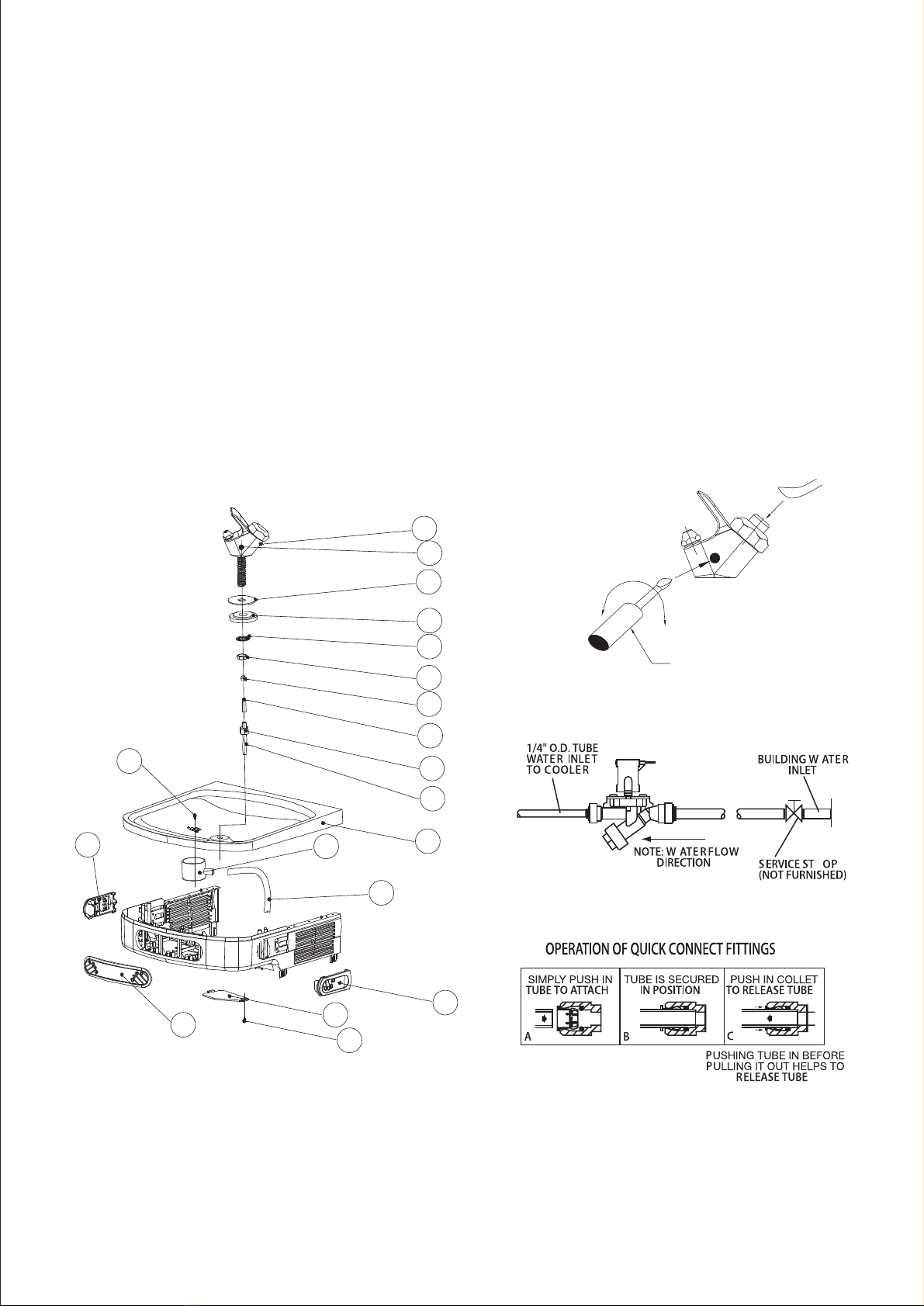
1) Remove hanger bracket fastened to back of cooler by removing one (1) screw. SEE FIGURE
3.
2) Mount the hanger bracket to the wall.
NOTE: Hanger Bracket MUST be supported securely. Add fixture support carrier if wall will not
provide adequate support. Anchor hanger securely to wall using all six (6) 1/4 in. dia. mounting
holes.
IMPORTANT:
5-7/8 in. (150mm) dimension from wall to centerline of trap must be maintained for proper fit.
INSTALLATION OF COOLER
3) Hang the cooler on the hanger bracket. Be certain the hanger bracket is engaged properly in
the slots on the cooler back as shown in FIGURE 3.
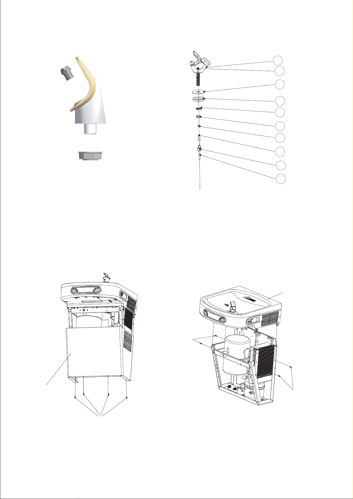
4) Remove the four (4) screws holding the lower front panel at the bottom of cooler. Remove the
front panel by pulling straight down and set aside, SEE FIG. 4, FIG.5.
WATER CONNECTION TO THE MAIN
5) Before making the water connection, make sure the mains water pressure is between 20 and
60 psi.
6) If the mains water pressure exceeds 60 psi, predispose a pressure reducer capable of reducing
the latter to the 20~60 psi.
7)Connection to the mains water supply is carried out with the aid of 1/4in PE tube
provided(dia 1/4").
8)The tube terminals (1/2”×1/4”fitting) must be connected to the mains supply by means of a
“water supply valve” G (not provided). SEE FIGURE 3.
FILLING INTERNAL ICE BANK
9) Remove the white plugs marked" Fill Ice Bank".
10) Connect water supply tube into the connector "Fill Ice Bank".
11)Open the "water supply valve" G, let the water enter the ice bank slowly and fill the ice bank;
once reach the right level, the exceeding water will run over the outlet of Overflow pipe, then close
"water supply valve" G. After that, connect water pipe into coupling-- "water in" with proper
pressure. SEE FIGURE 3.
Note: The connection of tank charge--"Fill Ice Bank" has to be disconnected.
12) Insert the white plug back to its original position(overflow).
DRAIN CONNECTION
The drain water is clean and it comes from the tray(basin) that collects any dripping during
dispensing.
Connect the drain pipe (O.D. 20mm) to drain with a drain-trap. If necessary, cut the pipe so as to
avoid narrowing or rising or backflow problems.
CLEANING
Warm, soapy water or mild household cleaning products can be used to clean the exterior panels
of the TB35 water coolers. Extra caution should be used to clean the mirror finished stainless steel
panels. They can be easily scratched and should only be cleaned with mild soap and water or
Windex glass cleaner and a clean, soft cloth. Use of harsh chemicals or petroleum based or abrasive
cleaners will void the Warranty.

Page 5 (Rev. A - 6/2012)
26
27
28
29
30
31
32
33
34
35
16
9
25
13
8
24
15
13
36
PUSH
SLOTTED
SCREWDRIVER
DECREASE
FLOW
INCREASE
FLOW
Service Instructions
Lower and Upper Shroud
To access the refrigeration system and plumbing connections, remove four screws from bottom of
cooler to remove the lower shroud. To remove the upper shroud for access to the pushbars,
regulator, solenoid valve or other components located in the top of the unit, remove lower shroud,
disconnect drain, remove four screws from tabs along lower edge of upper shroud, unplug two wires
and water tube. SEE FIG.4, FIG.5 & FIG.6.
Bubbler
To remove the bubbler, first disconnect the power supply. The underside of the bubbler can be
reached through the access panel (Item 8) on the underside of the upper shroud (Item 14). Remove
the access panel by removing the retaining screw (item 24) . To remove the bubbler, loosen locknut
(Item 29) from the underside of the bubbler and remove the tubing from the quick connect fitting.
After servicing, replace the access panel and self-tapping screw. SEE FIG.7.
FIGURE 6
FIGURE 7

Page 6 (Rev. A - 6/2012)
NOTE:
When installing replacement bubbler and pedestal, tighten
Nut only to hold parts snug in position. Do Not
Overtighten.
BUBBLER DETAIL
26
27
28
29
30
31
32
33
34
35
LOWER COVER
SCREWS
BASINASSEMBLY
SCREWS
SCREWS
FIGURE 4 FIGURE 5

(Rev. A - 6/2012)
Switch Activation
Closed Switch Detail
Open Switch Detail
Note: Only side push activation is shown.
Front push works the same.
Page 7
Table of contents
Popular Water Dispenser manuals by other brands

Borg & Overstrom
Borg & Overstrom b2 Install & Operation Manual

Sterling
Sterling IFS10 Installation instructions and owner's manual

TECNICOMAR
TECNICOMAR ECOmar S Series INSTRUCTIONS FOR THE INSTALLATION, USE AND MAINTENANCE

GE
GE GXSF30H Owner's Manual & Installation Instructions

Elkay
Elkay LVRCDWS A Series Installation and use manual

Halsey Taylor
Halsey Taylor Contour Series owner's manual