Kemper MINI-TRESOR User manual

DE Einbau- und Bedienungsanleitung
‘TRESOR‘ Wandaufputzschrank aus Edelstahl
Fig. 213 2
EN Installation and operating instructions
‘MINI-TRESOR‘ stainless steel surface-mounted wall cabinet
Fig. 213 6
FR Instructions d’installation et d’utilisation
Armoire murale encastrée «MINI-TRESOR» en acier inoxydable
Fig. 213 11
IT Istruzioni di montaggio e d‘uso
‘MINI- TRESOR’ Armadio a incasso a parete in acciaio inox
Afb. 213 16
CS Návod k montáži a obsluze
‘MINI-TRESOR‘ vestavěná skříňka z nerezové oceli
obr. 213 21
!

© www.kemper-olpe.de – 11.2021 / K410021300001-00 – 2/24
DE Sicherheitshinweise für Montage und Gebrauch
Verwendung
Der Wandeinbauschrank dient als Versorgungssta-
tion zur zentralen Wasser- bzw. Stromversorgung.
Jede andere Verwendung gilt als nicht
bestimmungsgemäß!
Anschlussmöglichkeiten: z. B.Wasser- und Strom-
anschluss für 230 V / 400 V, bauseits erweiterbar
z.B. um Gas-, Telefon-, Antennen- oder Abwasseran-
schluss, für die private und gewerbliche Anwendung.
Warnhinweise
Beachten und befolgen Sie die Warnhinweise in der
Anleitung. Nichtbeachten der Warnhinweise kann zu
Verletzungen oder Sachschäden führen!
Kennzeichnung wichtiger Warnhinweise:
Gefahr! Elektrischer Strom!
Kennzeichnet Gefahren, die schwere
oder tödliche Verletzungen zur
Folge haben können.
Warnung! Kennzeichnet Gefahren,
die zu Verletzungen, Sachschäden
oder Verunreinigung des Trinkwassers
führen können.
Hinweis! Kennzeichnet Gefahren,
die zu Schäden an der Anlage oder
Funktionsstörungen führen können.
Info! Kennzeichnet zusätzliche
Informationen und Tipps.
Wichtige Hinweise für den Anlagenbetreiber
Material: Edelstahl
Druckstufe Armatur: PN 16
Verwenden Sie das Gerät
- nur in einwandfreiem Zustand
- bestimmungsgemäß
Hinweis! Das Sicherheitstürschloss
ist umrüstbar auf ein bestehendes
Schließsystem. Hierzu ist das Türschloss
auszutauschen.
Hinweis! Die Elektro- und Sanitär-
installationen sind jeweils vom
Fachinstallateur auszuführen.
Hinweis! Der gesamte Tresor ist in
regelmäßigen Abständen mit einem
Edelstahlreinigungsmittel zu reinigen!
Pege der Schrankoberäche:
Aggressive und scheuernde Reinigungs-
mittel können die Oberäche beschädigen.
Keine chlor- oder säurehaltigen, schlei-
fenden oder ätzenden Reinigungsmittel
verwenden. Die Reinigung wird mittels
feuchtem Mikrofasertuch empfohlen.
Montage und Gebrauch
Anleitung vor Montagebeginn oder Gebrauch sorg-
fältig lesen und den Anweisungen folgen! Montage
und Funktionsprüfung nur durch sachkundige,
qualizierte Fachkraft.
Anleitung an den Anlagenbetreiber weitergeben und
zur späteren Verfügung aufbewahren!
Warnung! Nationale Normen und Vorschriften zur
Sanitärinstallation sowie zur Unfallverhütung sind
vorrangig zu befolgen.
Hinweis! Einbauort muss ein geschlossener,
trockener und frostfreier Raum sein, der nicht
überutet werden kann.
Hinweis! Vor Abschluss der Montage unbedingt
eine Dichtigkeitsprüfung der wasserführenden
Elemente sowie eine Funktionsprüfung durchführen.
Haftung
Keine Gewährleistung oder Haftung bei:
- Nichtbeachten der Anleitung.
- fehlerhaftem Einbau und/oder Gebrauch.
- eigenständiger Modikation am Produkt.
- sonstiger fehlerhafter Bedienung.

© www.kemper-olpe.de – 11.2021 / K410021300001-00 – 3/24
DE
Hinweis! Die Armatur muss mind. 250 mm
über dem höchstmöglichen Betriebswas-
serspiegel eingebaut werden!
Hinweis! Die Verwendung als Verteiler
für Wasser und Strom ist nicht in allen
Ländern zulässig! Beachten Sie eventuell
bestehende landesspezische Regelungen,
falls Sie beabsichtigen, den Verteiler
außerhalb Deutschlands zu verwenden.
Hinweis! Bei Einbau des Tresors in
Schwimmbädern oder Einrichtungen mit
vergleichbaren Umgebungsbedingungen,
ist eine regelmäßige Reinigung des
gesamten Tresors, wie vorher beschrieben,
notwendig.
Gefahr! Lt.VDE-Bestimmungen muss der
KEMPER MINI-TRESOR für Strom- und
Wasseranschluss durch einen FI-Schalter
(Fehlerstrom 0,03A) abgesichert werden.
Dies gilt für alle Steckdosen im Außenbereich.
Entsorgung
Örtliche Vorschriften zur Abfallver-
wertung bzw. -beseitigung sind zu
beachten. Produkt darf nicht mit
normalem Haushaltsmüll, sondern muss
sachgemäß entsorgt werden.
Bezeichnung
1 Wandaufputzschrank (Grundkörper)
2 4 Befestigungsschrauben und 4 Abstandshalter
3 Frostsichere Außenarmatur oder Geräteanschlussventil
4 2 Befestigungsschrauben (M6 x 12)
5 Steckdose je nach gewählter Figurnummer
6 Montageplatte mit Befestigungsbügel
7 Flügelschrauben
8 Spritzschutzblech
9 2 Befestigungsschrauben (M6 x 12)
10 Türschloss mit 3 Schlüsseln

© www.kemper-olpe.de – 11.2021 / K410021300001-00 – 4 /24
Den Wandaufputzschrank an der Außenwand ausrichten und die vier
Bohrlöcher (Ø 8 mm) sowie die Bohrung für die frostsichere
Außenarmatur (Ø 27 mm) kennzeichnen und bohren.
Schrank (1) mittels beiliegenden vier Abstandshaltern und
Befestigungsschrauben (2) an der Außenwand befestigen.
Gefahr! Erdung!
Verbindung des Potentialausgleichs mit den dafür vorgesehenen
Schrauben im oberen Wandeinbauschrankbereich und an der
Tür herstellen (sämtliche metallischen Teile sind somit geerdet).
Metallende Gebäudeteile, zu denen auch der Tresor gehört
benötigen zwingend die Verbindung zum Potentialausgleich.
Querschnitt dieser Leitungen ist die Hälfte des Querschnitts
des Hauptschutzleiters, mindestens jedoch 6 mm².
Steckdosenkombination (5) (Anschlussfertig verdrahtet) auf
Montageblech (6) aufschrauben, im Wandeinbauschrank (1) anschließen
und mit der Flügelschraube (7) an der Schrankwand xieren
(20° schwenkbar).
Hinweis!
Funktionsprüfung durchführen!
Gefahr!
Elektroarbeiten dürfen nur von autorisiertem Fachpersonal
ausgeführt werden!
Stromzuführung vorsehen
- FI-Absicherung beachten:
Nennfehlerstrom ≤ 0,03 A und
Anschlussleistung ≤32 A
- Schutzart IP 44
DE 12
Montage Wandaufputzschrank Einbau Steckdosenkombination
1. 1.
2.
Info! Folgende
Figuren werden mit der
Schutzart IP 55
ausgeliefert:
21302015CH
21303015CH
21304015CH

© www.kemper-olpe.de – 11.2021 / K410021300001-00 – 5 /24
DE 34
Montage frostsichere Außen-
armatur und Spritzschutz Funktionsprüfung
Frostsichere Außenarmatur (3) in die Bohrung stecken und mittels der
zwei beiliegenden M6-Schrauben (4) befestigen.
Außenarmatur (3) an die Wasserleitung anschließen
(Cu-Rohr Ø 15 mm oder AG R ½“).
Das Spritzschutzblech (8) mit der mittigen Bohrung (Ø 35 mm) unterhalb
der frostsicheren Außenarmatur einführen und mit den beigefügten
Schrauben M6 (9) an den vorgesehenen Befestigungspunkten an der
Rückwand verbinden.
Warnung!
Montage nur durch sachkundige, qualizierte Fachkraft!
Hinweis!
Ventilsitz (Gewinde R ½“) muss im frostfreien Bereich liegen.
Hinweis!
Die Mindestwandstärke von 180 mm Mauerwerk darf nicht
unterschritten werden (s. frostfreier Bereich).
Funktionsprüfung der Frostsicheren Außenarmatur (3) durchführen.
Hinweis!
Durch das selbständige Entleeren der Frostsicheren Außenarmatur
(3) nach dem Zapfvorgang läuft das Wasser nach dem Absperren
für einige Sekunden nach (Frostsicherheit). Es ist aus diesem
Grunde nur leichtes Zudrehen (Schließen) der Armatur erforderlich.
Hinweis!
Zur Sicherstellung der Funktion „Frostsicherheit“ müssen
Schläuche und sonstige Anbauteile vor Beginn der Frostperiode
entfernt werden!
1.
1.
2.
3.

© www.kemper-olpe.de – 11.2021 / K410021300001-00 – 6 /24
EN
Use
The built-in wall cabinet serves as a supply station
for the central water and power supply.
Any other uses constitute misuse.
Connection options: e. g. water and power connec-
tion for 230 V / 400 V, can be expanded on site, e.g.
by gas, telephone, antenna or waste water connecti-
on, for private and commercial use.
Warning information
Please read and follow the warning information in
this instruction. Disregard of the warning informati-
on may lead to injury or material damage!
Labelling of important warning information:
Danger! Electricity!
Indicates hazards that might result
in severe or fatal injury.
Warning! Highlights risks that may
result in injury, material damage or
contamination of drinking water.
Note! Indicates hazards that may
lead to damages to the system or
malfunctions.
Info! Indicates additional
information and tips.
Important advice to the operator
Material: Stainless steel
Pressure rate valve: PN 16
Only use the TRESOR
- in sound condition
- as intended
Note! The door lock can be replaced
with an existing locking system. The door
lock must be replaced for this purpose.
Note! The electrical and plumbing
installations must be carried out by
specialist installers.
Note! The complete Tresor must be
cleaned by a stainless steel cleaning
agent in regular intervals!
Care of the cabinet surface: Aggressive
and scour cleaning agents can damage
the surface. Don´t use chloric or acidic,
grinding or acidly cleaning agents.
Cleaningwithadampmicro-brecloth
is recommended.
Installation and operation
Read the manual carefully and follow the
instructions before installation!
Installation and maintenance must be
carriedoutbyqualiedplumbers.
Always pass on this manual to the current
system owner and keep it in a safe place for
future reference!
Warning! Priority must be given to the national
standards and provisions on sanitary
installations and accident prevention.
Warning! The installation location must be a closed,
dryandfrost-freeroomthatcannotbeooded.
Warning! Before completing the installation, it is
essential to carry out a leak test of the water-bea-
ring elements as well as a functional test.
Warranty
Warranty or liability are voided through:
- Disregard of installation instructions.
- Damage due to faulty installation.
-Unauthorisedproductmodications.
- Other incorrect operation.
Precautions for installation

© www.kemper-olpe.de – 11.2021 / K410021300001-00 – 7 /24
EN
Note! The valve must be attached
minimum 250 mm over the
maximum of operating water surface.
Note! In some countries the use of
combination units with water and
electric is not permitted. Please follow
thespecicregulationsfortherelevant
country, if you want to install the
product outside of Germany.
Note! In case of assembly the Tresor
in swimming pools or facilities with
compareable ambient conditions, a
regular cleaning of the complete Tresor
is necessary as described before.
Danger! According to VDE requirements
KEMPER MINI-TRESOR for power and
water connection have to fuse by a
residual current circuit breaker (residual
current 0,03A). This applies to all sockets
in outdoor area.
Disposal
Local regulations on waste recycling and
disposal must be followed. The product
must not be disposed of with household
waste but must rather be disposed of
appropriately.
Description
1 Surface-mounted wall cabinet (basic body)
2 4 attachment screws and 4 spacers
3Frost-proofouterttingorhosebibb
4 2 attachment screws (M6 x 12)
5SockettotselectedFiguretype
6 Mounting plate with attachment clasp
7 Wing-screws
8 Spray protection plate
9 2 attachment screws (M6 x 12)
10 Door lock with 3 keys

© www.kemper-olpe.de – 11.2021 / K410021300001-00 – 8 /24
Screw the 230 V socket (5) onto the mounting plate (6), connect in the
surface-mounted wall cabinet (1) and attach to the cabinet rear wall
using the screws supplied (7).
Note!
Carry out a functional test!
Danger!
Electrical work must be carried out only by authorised
specialist personnel!
Align the surface-mounted wall cabinet on the outer wall, and mark and
drillthefourholes(Ø8mm)andtheholeforthefrost-freeoutertting
(Ø 27 mm).
Attach the cabinet (1) to the outer wall using the four spacers and
attachment screws (2).
Danger! Earthing!
Connect the earthing with the intended screws at the upper part
of the wall cabinet and the door (All metallic parts are earthed by
this). Metallic parts of the building, to which the wall cabinet
belongs, have to be earthed.
The cross section of the wire is half the cross section of the main
earth wire of the building, or at least 6 mm².
Provide the power supply
- Note FI fuse:
Nominalfaultcurrent≤0.03A,
connectioncurrent≤16Aand
connection voltage 230 V
- Protection type IP 44
1. 1.
2.
Info! Followinggures
are delivered with
protection type IP 55:
ausgeliefert:
21302015CH
21303015CH
21304015CH
EN 12
Installation of surface-
mounted wall cabinet Installation of socket combination

© www.kemper-olpe.de – 11.2021 / K410021300001-00 – 9 /24
EN 3Installation of frost-proof outer
tting and spray protection
Insertthefrost-proofoutertting(3)intotheholeandattachusingthe
two M6 screws (4) provided.
Connecttheoutertting(3)tothewatersupply
(copper pipe Ø 15 mm or AG R ½“)
Insert the spray protection plate (8) with the central hole (Ø 35 mm)
belowthefrost-proofoutertting,andconnecttotheattachmentpoints
provided on the rear wall using the M6 screws provided (9).
Warning!
Installationmustbecarriedoutbyqualiedplumbers!
Note!
The valve seat (thread R ½“) must be located in
the frostfree area.
Note!
The masonry must be at least 180 mm thick (see frost-free area).
4
Conductfunctionaltestingofthefrost-proofoutertting(3).
Note!
Duetotheautomaticdrainingofthefrost-proofoutertting(3)
after removal of water, water will continue to drain out for a few
secondsafterclosingthetting(frostsafety).Forthisreason,the
ttingonlyneedstobeclosedgently.
Note!
To ensure the correct ‘frost safety‘ function, hoses and other
attachements must be removed before the start of the frost
period!
Functional testing
1.
1.2.
3.

© www.kemper-olpe.de – 11.2021 / K410021300001-00 – 10 /24
FR Consignes de sécurité pour le montage
Remarques importantes
L’armoire murale encastrée sert de station centralisée
pour l’alimentation en eau et l’alimentation en électri-
cité. Toute autre utilisation est considérée comme non
conforme à la destination prévue!
Possibilités de raccordement/ par ex. raccordement
d‘eau et d‘électricité pour 230 V / 400 V, qui peut être
étendu sur site par ex. par gaz, téléphone, antenne ou
raccordement d‘eau pour usage privé et professionnel.
Avertissements
Tenez compte et respectez impérativement les
avertissements de la notice. Le non-respect des
avertissements peut entraîner des blessures ou des
dommages matériels!
Marquage des avertissements importants:
Danger! Courant électrique! Indique les
dangers pouvant entraîner la mort ou
des blessures graves.
Avertissement! Indique les dangers
pouvant entraîner des blessures, des
dégâts matériels ou une contamination
de l‘eau potable.
Remarque! Indique les dangers pouvant
entraîner des détériorations sur l‘instal
lation ou des dysfonctionnements.
Info! Indique des informations
supplémentaires et conseils.
pour l’exploitant de l’installation
Matériau: Acier inoxydable
Niveau de pression de la vanne/ PN 16
N’utilisez l’appareil
- que s’il est dans un état irréprochable et
- que conformément à la destination prévue
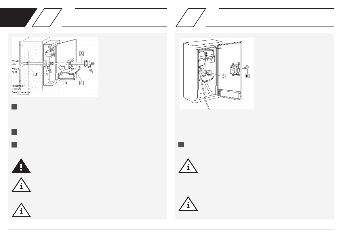
Remarque! La serrure à mortaise de sé
curité peut être adaptée à un système de
verrouillage existant À cet effet, il convient
de remplacer la serrure de la porte.
Remarque! Les installations électriques
et sanitaires doivent être réalisées par
uninstallateurqualié.
Remarque! Le «Tresor» complet doit
être nettoyé à intervalles réguliers avec
un produit de nettoyage spécial pour acier
inox! Entretien de la surface de l’armoire:
Les produits de nettoyage agressifs ou
abrasifs peuvent endommager la surface. Ne
pas utiliser des produits de nettoyage
chlorés ou acides, abrasifs ou corrosifs.
Nous recommandons d’utiliser un chiffon en
microbreshumidespourlenettoyage.
Montage et utilisation
Lisez soigneusement la notice avant le montage ou
l’utilisation et respectez les instructions! Seul un
technicienqualiéetcompétentenlamatièreest
autorisé à effectuer le montage et le contrôle foncti-
onnel. Remettez la notice à l‘exploitant de l’installa-
tion et conservez-la comme référence à l’avenir!
Avertissement! Les normes nationales, les régle-
mentations en matière d’installations sanitaires et
les prescriptions de prévention des accidents doivent
être suivies en priorité.
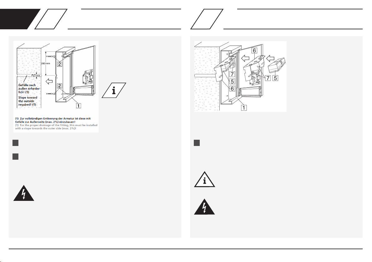
Remarque! Le lieu d’installation doit être un local fermé,
sec et à l’abri du gel, qui ne puisse pas être inondé.
Remarque!Avantlandumontage,effectuez
impérativement un contrôle d’étanchéité des élé-
ments conducteurs d’eau, de même qu’un contrôle
fonctionnel.
Responsabilité
Aucune responsabilité ni aucune garantie dans les
cas suivants:
- non-respect de la notice,
- installation et/ou d’utilisation incorrecte(s),
-modicationarbitraireduproduit,
- en cas de toute autre utilisation inappropriée.

© www.kemper-olpe.de – 11.2021 / K410021300001-00 – 11 /24
FR
Remarque! La vanne doit être installée au
moins 250 mm au-dessus du niveau d’eau
de service le plus haut qui soit possible!
Remarque! L’utilisation comme
distributeur d’eau et électrique n’est pas
autorisé dans tous les pays! Veuillez observer
les réglementations nationales éventuelles, si
vous souhaitez utiliser le distributeur dans
un autre pays que l’Allemagne.
Remarque! Dans le cas d’un montage
du «Tresor» dans les piscines ou installa-
tions présentant des conditions ambiantes
similaires, le nettoyage régulier du
«Tresor» complet est nécessaire,
conformément à la description ci-dessus.
Danger! Selon les dispositions VDE, le
«KEMPER MINI-TRESOR» pour branche-
ments électriques et d’eau doit être
protégé par un interrupteur de protection
contre les courants de court-circuits
(courants de fuite 0,03A) Cela s‘applique
à toutes les prises électriques extérieures.
Mise au rebut
Il faut tenir compte des prescriptions
locales relatives au recyclage et à
l’élimination des déchets. Il est interdit
de jeter le produit dans les ordures
ménagères. Il faut, par contre, le mettre
au rebut de manière appropriée.
Désignation
1 Armoire murale apparente (châssis de base)
24visdexationet4écarteurs
3 Robinets extérieurs résistant au gel ou robinets extérieurs standard
42visdexation(M6x12)
5Priseenfonctiondunumérodegurechoisi
6Plaquedemontageavecétrierdexation
7 Vis papillon
8 Tôle antiprojections
92visdexation(M6x12)
10 Serrure de porte avec 3 clés

© www.kemper-olpe.de – 11.2021 / K410021300001-00 – 12 /24
Aligner l’armoire murale apparente sur le mur extérieur et marquer, puis
percer les quatre trous (Ø 8 mm) ainsi que le trou pour le robinet extéri
eur résistant au gel (Ø 27 mm).
Fixerl’armoire(1)aumoyendesquatreentretoisesetvisdexation(2)
fournis sur le mur extérieur.
Danger! Mise à la terre!
Effectuer le branchement de la compensation de potentiel à l’aide
des vis prévues à cet effet dans la partie supérieure de l’armoire
murale encastrée et sur la porte (tous les éléments métalliques
sont alors mis à la terre). Les éléments métalliques du bâtiment,
dont le «Tresor» fait partie, requièrent impérativement le raccor
dement à la compensation du potentiel. La section de ces câbles
correspond à la moitié de la section du conducteur de terre
principal et est au minimum de 6 mm².
révoir une alimentation électrique
- Tenir compte de la protection
contre les courants de court-
circuits: Courant de fuite nominal
≤0,03A,puissanceconnectée
≤16Aetalimentationélectrique230V
- Type de protection IP44
Visser la prise 230 V (5) sur la plaque de montage (6). Brancher l’armoire
muraleapparente(1)etlaxerparlacloisonarrièreàl’aidedesvis(7)
fournies.
Remarque!
Effectuer un contrôle fonctionnel!
Danger!
Uniquement un technicien spécialisé agréé est autorisé
à effectuer les interventions électriques!
1. 1.
2.
Info! Followingguresare
delivered with protection
type IP 55:
21302015CH I 21303015CH
21304015CH
FR 12
Montage de l’armoire
murale apparente Installation de la combinaison prise

© www.kemper-olpe.de – 11.2021 / K410021300001-00 – 13 /24
FR 3Montage du robinet extérieur résistant
au gel et de la protection antiprojections
Insérerlerobinetextérieurrésistantaugel(3)dansletrouetlexerau
moyen des deux vis M6 (4) fournies.
Brancher le robinet extérieur (3) à la conduite d’eau
(tube en cuivre Ø 15 mm ou AG R ½“).
Introduire la tôle antiprojections (8) par le trou central (Ø 35 mm) sous
lerobinetextérieurrésistantaugeletlexerauxpointsprévussurla
cloison arrière au moyen des vis M6 (9) fournies.
Avertissement!
Seuluntechnicienqualiéetcompétentenlamatièreest
autorisé à effectuer le montage!
Remarque!
Lesiègedelavanne(letageR½“)doitsetrouverdanslazonehorsgel.
Remarque!
L’épaisseur minimale de 180 mm pour la maçonnerie doit être
respectée impérativement (voir zone hors gel).
4Essai fonctionnel
Effectuer l’essai fonctionnel du robinet extérieur résistant au gel (3).
Remarque!
En raison de la vidange automatique du robinet extérieur
résistant au gel (3) après le processus de prélèvement, l’eau
continue à s’écouler pendant quelques secondes après la
fermeturedurobinet(protectionantigel).Decefait,ilsuft
de serrer légèrement le robinet pour le fermer.
Remarque!
Pour assurer la fonction «Protection antigel», les tuyaux ou autres
éléments rapportés doivent être retirés avant la saison froide!
1.
1.
2.
3.

© www.kemper-olpe.de – 11.2021 / K410021300001-00 – 14 /24
IT Avvertenze di sicurezza per il montaggio
Avvertenze importanti
Questo armadio a parete serve da punto unico di
alimentazione per la fornitura centralizzata di acqua
e di corrente. Qualsiasi altro utilizzo viene conside-
rato non conforme!
Possibilità di collegamento: ad es. allaccio di acqua e
corrente per 230 V / 400 V, con possibilità di estensi-
one sul posto, ad es. all‘acciamento di gas, telefono,
antenna e acqua di scarico per l‘uso in ambito
privato e commerciale.
Avvertenze
Attenersi scrupolosamente alle avvertenze riportate
nelle istruzioni. La mancata osservanza delle avver-
tenze può causare lesioni o danni materiali!
Segnalazione di avvertenze importanti:
Pericolo! Corrente elettrica! Indica i
pericoli che possono avere come
conseguenza lesioni gravi o mortali.
Attenzione! Indica i pericoli che
possono causare lesioni, danni materiali
o inquinamento dell’acqua potabile.
Nota! Indica i pericoli che possono
causare danni all’impianto o
malfunzionamenti.
Informazioni! Indica ulteriori
informazioni e suggerimenti.
per il gestore dell’impianto
Materiale: acciaio inox Livello di pressione
rubinetto: PN 16
Utilizzare l’apparecchio
- soltanto se è in perfette condizioni
- e conformemente a quanto indicato.
Nota! La serratura di sicurezza può
essere montata su un sistema di
chiusuragiàesistente(retrot).Per
questo è necessario sostituire la serratura.
Nota! Gli impianti elettrici e sanitari
devono essere realizzati da un
installatore specializzato.
Nota! Tutto l’armadio Tresor deve essere
pulito a intervalli regolari con un
detergente per acciaio inox!
Manutenzione della parte esterna
dell’armadio: i detergenti aggressivi e
abrasivipossonodanneggiarelasupercie.
Evitare di utilizzare detergenti abrasivi o
corrosivi, a base di cloro o acidi. Per la
pulizia si consiglia di utilizzare un panno
morbidodimicrobra.
Montaggio e utilizzo
Leggere attentamente queste istruzioni prima di
avviare la procedura di montaggio o prima dell’uti-
lizzo e attenersi alle indicazioni fornite! Montaggio
evericadelfunzionamentodevonoessereeseguiti
solodapersonalespecializzatoespertoequalicato.
Consegnare le istruzioni al gestore dell’impianto e
conservarle per poterle consultare in seguito!
Attenzione! Attenersi in via prioritaria alle norme
e alle disposizioni nazionali in materia di impianti
sanitari e di prevenzione degli infortuni.
Nota! L’installazione deve essere eseguita in uno
spazio chiuso, asciutto e riparato dal gelo, dove non
possanovericarsiallagamenti.
Nota! Prima di concludere il montaggio è necessario
eseguireunavericadellatenutadeicomponenti
idrauliciasiemaunavericadelfunzionamento.
Responsabilità
Si esclude qualsiasi garanzia o responsabilità in caso di:
- mancata osservanza delle istruzioni.
- installazione e/o utilizzo errato.
-modicaarbitrariadelprodotto.
- altro impiego non conforme.

© www.kemper-olpe.de – 11.2021 / K410021300001-00 – 15 /24
IT
Nota! Il rubinetto deve essere installato
almeno 250 mm al di sopra del massimo
livello possibile per l’acqua a scopo non
potabile!
Nota! L’utilizzo di questo sistema per la
distribuzione di acqua ed elettricità non
è consentito in tutti i paesi! Attenersi
ai regolamenti eventualmente in vigore
inognispecicopaesesesiprevededi
utilizzare questo distributore fuori dalla
Germania.
Nota! L’installazione del sistema Tresor
in piscine o in strutture con ambienti che
presentano caratteristiche simili richiede
necessariamente una pulizia regolare di
tutto l’armadio come già illustrato in
precedenza.
Pericolo! Secondo le normative VDE
[associazione tedesca per le tecnologie
elettriche, elettroniche ed informatiche]
il sistema MINI-TRESOR di KEMPER per
l‘allaccio di acqua e corrente deve essere
protetto da un interruttore FI (corrente
differenziale0,03A).Questorequisito
vale per tutte le prese in ambienti esterni.
Smaltimento
Attenersi alle disposizioni locali in
materiadiricicloosmaltimentodeiriuti.
Il prodotto non può essere gettato via
coninormaliriutidomestici,bensìdeve
essere smaltito in modo appropriato.
Definizioni
1Armadioesternoaparete(corpobase)
24vitidissaggioe4distanziatori
3 Rubinetto esterno antigelo o valvola di collegamento apparecchio
42vitidissaggio(M6x12)
5 Presa in base al rispettivo codice articolo selezionato
6Piastradimontaggioconstaffadissaggio
7 Viti ad alette
8 Piastra para-spruzzi
92vitidissaggio(M6x12)
10 Serratura con 3 chiavi

© www.kemper-olpe.de – 11.2021 / K410021300001-00 – 16 /24
Allineare l’armadio esterno a parete sulla parete esterna, segnare i
quattropuntidaforare(Ø8mm)eilforoperilrubinettoesterno
antigelo(Ø27mm)edeseguireifori.
Fissarel’armadio(1)sullapareteesternautilizzandoiquattro
distanziatorielevitidissaggiofornite(2).
Pericolo! Messa a terra!
Collegare la compensazione di potenziale con le viti previste
per tale scopo nella parte superiore dell’armadio a incasso a
pareteesullosportello(cosìtuttelepartidimetallosono
collegateamassa).Leparticonestremitàinmetallodel
fabbricato che include anche Tresor devono essere
necessariamente allacciate con un collegamento equipotenziale.
La sezione di questi cavi misura la metà della sezione del
conduttore di protezione principale o comunque almeno 6 mm².
Predisporre l’alimentazione di
corrente
- Fare attenzione alla protezione
FI: corrente differenziale nominale
≤0,03Aepotenzaallacciata≤32A
- Grado di protezione IP 44
Informazioni! Gli articoli
che seguono sono forniti
con grado di protezione
IP 55:
ausgeliefert: 21302015CH
21303015CH 21304015CH
IT 12
Montaggio dell’armadio
esterno a parete
Installazione della
combinazione di prese
Avvitarelapresada230V(5)sullapiastradimontaggio(6),
collegarlanell’armadioesternoaparete(1)essarlasullaparete
posterioreutilizzandolevitifornite(7).
Nota!
Eseguireunavericadelfunzionamento!
Pericolo!
Gli interventi elettrici devono essere eseguiti soltanto da persone
specializzate autorizzate!
1. 1.
2.

© www.kemper-olpe.de – 11.2021 / K410021300001-00 – 17 /24
IT 34
Montaggio del rubinetto esterno
antigelo e del para-spruzzi
Inserirenelforoilrubinettoesternoantigelo(3)essarloutilizzando
leduevitiM6fornite(4).
Collegareilrubinettoesterno(3)altubodell’acqua
((tuboinrameconØ15mmolett.est.R½“).
Inserirelapiastrapara-spruzzi(9)conilforocentrale(Ø35mm)sottoal
rubinettoesternoantigeloecollegarlaaipuntiissaggioprevistisulla
pareteposterioreutilizzandolevitiM6fornite(9).
Attenzione!
Montaggio eseguito esclusivamente da personale specializzato
espertoequalicato!
Nota!
Lasededellavalvola(lettaturaR½“)devetrovarsiinunpunto
riparato dal gelo.
Nota!
Non superare lo spessore minimo della parete di 180 mm della
muratura(v.zonaalriparodalgelo).
Verica del funzionamento
Eseguireunavericadelfunzionamentodelrubinettoesternoantigelo(3)
Nota!
Conlosvuotamentoautomaticodelrubinettoesternoantigelo(3)
al termine dell’erogazione, l’acqua continua a scorrere per alcuni
secondidopocheilrubinettoèstatochiuso(protezioneantigelo).
Perquestomotivoilrubinettodeveessereruotato(chiuso)senza
stringere troppo.
Nota!
Pergarantirelafunzionedi“protezioneantigelo”,primacheinizi
lastagionedellegelateènecessariorimuovereitubiessibilie
gli altri pezzi aggiuntivi!
1.
2.
3. 1.

© www.kemper-olpe.de – 11.2021 / K410021300001-00 – 18 /24
CS Bezpečnostní pokyny pro montáž
použití se hodnotí jako použití v rozporu s účelem!
Možnosti připojení např. přívod vody a proudu pro
230 V / 400 V, na místě montáže možné rozšířit
např. o plynovou, telefonní, anténní nebo přívpojku
nebo přívod odpadní vody pro soukromé a komerční
použití.
Výstražná upozornění
Dodržujte a řiďte se výstražnými upozorněními, které
jsou uvedena v návodu. Nedodržování výstražných
upozornění může mít za následek zranění nebo
věcné škody!
Označení důležitých upozornění:
Nebezpečí! Elektrický proud! Označuje
nebezpečí, která mohou mít za následek
vážné nebo smrtelné úrazy.
Výstraha! Označuje nebezpečí, která
mohou vést ke zraněním, věcným ško
dám nebo znečištění pitné vody.
Upozornění! Označuje nebezpečí, která
mohou vést k poškození zařízení nebo
poruchám funkčnosti.
Informace! Označuje dodatečné
informace a tipy.
pro provozovatele zařízení
Materiál: Nerezový tlakový stupeň
armatury: PN 16
Přístroj používejte
- pouze v bezchybném stavu
- v souladu s určením
Upozornění! Bezpečnostní dveřní
zámek lze přestavět na aktuální uza
vírací systém. K tomu se musí vyměnit
dveřní zámek.
Upozornění! Elektrickou a sanitární
instalaci musí provádět odborný
instalatér.
Upozornění! Celý trezor se musí čisti v
pravidelných intervalech pomocí čisticího
prostředku na nerezové povrchy!
Péče o povrch skříně: Agresivní a abra
zivní čisticí prostředky mohou poškodit
povrch. Nepoužívejte žádné brusné nebo
žíravé čisticí prostředky s obsahem
chlóru nebo kyselin. Doporučujeme
provádět čištění pomocí vlhké
mikrovláknové utěrky.
Montáž a použití Použití
Před montáží nebo použitím si pozorně přečtěte
návod a postupujte podle pokynů! Montáž a funkcí
smí provádět pouze odborný, kvalikovaný personál.
Návod odevzdejte provozovateli zařízení a uschovej-
te, aby byl později k dispozici!
Výstraha! Vždy v první řadě respektujte vnitrostátní
normy a předpisy pro instalaci sanitárního materiálu,
jakož i prevenci úrazů.
Upozornění! Místo montáže musí být uzavřený,
suchý a mrazuvzdorný prostor, který nemůže být
zaplavený.
Upozornění! Před ukončením montáže bezpodmí-
nečně proveďte kontrola těsnosti prvků,
kterými protéká voda a kontrolu funkce.
Ručení
Žádná záruka nebo ručení při:
- nedodržování návodu.
- chybné montáži anebo provozu.
- svévolné úpravy na výrobku.
- jiné chybné obsluze.
Důležitá upozornění
Vestavěná skříňka slouží jako zásobovací stanice
pro centrální rozvod vody resp. elektřiny. Každé jiné

© www.kemper-olpe.de – 11.2021 / K410021300001-00 – 19 /24
CS
Označení
1Nástěnná skříňka (základní těleso)
24 upevňovací šrouby a 4 distanční držák
3Mrazuvzdorná venkovní armatura nebo ventil k připojení přístroje
42 upevňovací šrouby (M6 x 12)
5Zásuvka podle zvoleného čísla obrázku
6 Montážní deska s upevňovacím třmenem
7Křídlové šrouby
8Ochranný plech proti rozstřiku
92 upevňovací šrouby (M6 x 12)
10 Dveřní zámek se 3 klíči
Upozornění! Armatura se musí
namontovat min. 250 mm nad
maximální hladinu provozní vody!
Upozornění! Použití jako rozvaděč vody
a elektřiny není povolené ve všech
zemích. Postupujte případně podle
aktuálních národních pravidel, pokud
chcete rozvaděč použít mimo Německo.
Upozornění! Při montáži trezoru v
bazénech nebo zařízeních se
srovnatelnými okolními podmínkami je
nutné Pravidelné čištění celého trezoru,
jak je popsáno výše.
Nebezpečí! Podle ustanovení VDE musí
být mini TREZOR KEMPER přívod vody
a proudu vybavený nadproudovým
chráničem (chybný proud 0,03A). To
platí pro všechny venkovní zásuvky.
Likvidace
Respektujte místní předpisy pro recyklaci
resp. likvidaci. Produkt se nesmí
vyhazovat do normálního domovního
odpadu, nýbrž se musí řádně zlikvidovat.

© www.kemper-olpe.de – 11.2021 / K410021300001-00 – 20 /24
Nástěnnou skříňku vyrovnejte na vnější stěně a označte a vyvrtejte čtyři
otvory (Ø 8 mm) a otvor pro mrazuvzdornou venkovní armaturu (Ø 27 mm).
Skříňku (1) připevněte k vnější stěně pomocí čtyř distančních držáků a
upevňovacích šroubů (2).
Nebezpečí! Uzemnění!
Vodivě propojte s k tomu určenými šrouby v horní části vestavěné
skříňky a na dveřích (tak dojde k uzemnění všech kovových částí).
Kovové části budovy, ke kterým patří také trezor, vyžadují nutně
vodivé propojení. Průřez těchto vodičů je polovina průřezu hla
vního ochranného vodiče, minimálně ale 6 mm².
Ánování přívodu proudu
- Nezapomeňte na nadproudovou
ochranu: Jmenovitý chybný proud
≤ 0,03 A a připojovací výkon
≤32 A
- Třída krytí IP 44
Zásuvku 230 V našroubujte na montážní desky (6), připojte do nástěnné
skříňky (1) a pomocí přiložených šroubů (7) připevněte na zadní stěnu.
Upozornění!
Proveďte kontrolu funkce!
Nebezpečí!
Práce na elektrické instalaci smějí provádět pouze autorizovaní
odborníci!
1. 1.
2.
Informace! Následující
pozice se dodávají s
třídou krytí IP 55:
21302015CH
21303015CH
21304015CH
CS 12
Montáž nástěnné skříňky Montáž kombinace zásuvek
Other manuals for MINI-TRESOR
4
Table of contents
Languages:
Popular Indoor Furnishing manuals by other brands

Kis
Kis UP cabinet 009851 Assembly instruction

Seaside Casual
Seaside Casual Adirondack Coffee Table Assembly instructions

Northridge
Northridge 9V320V30 Assembly instructions

Monarch Specialties
Monarch Specialties I 3620 Assembly instructions

mosh
mosh MSH-SEC-T1 user manual

Schildmeyer
Schildmeyer 734185 Assembly instructions