Kemper MINI-TRESOR User manual

!
DE Einbau- und Bedienungsanleitung
‘MINI-TRESOR‘ Wandaufputzschrank aus Edelstahl
Fig. 212
EN Installation and operating instructions
‘MINI-TRESOR‘ stainless steel surface-mounted wall cabinet
Fig. 212
2
6

2 / 12 – K410021200001-00 / 09.2021 – ©www.kemper-olpe.de
Verwendung
Der Wandeinbauschrank dient als Versorgungs-
station zur zentralen Wasser- bzw. Stromver-
sorgung. Jede andere Verwendung gilt als nicht
bestimmungsgemäß!
Anschlussmöglichkeiten: z. B. Wasser- und Strom-
anschluss für 230 V / 400 V, bauseits erwei-
terbar z.B. um Gas-, Telefon-, Antennen- oder
Abwasseranschluss, für die private und gewerb-
liche Anwendung.
Warnhinweise
Beachten und befolgen Sie die Warnhinweise in
der Anleitung. Nichtbeachten der Warnhinweise
kann zu Verletzungen oder Sachschäden führen!
Kennzeichnung wichtiger Warnhinweise:
Gefahr! Elektrischer Strom!
Kennzeichnet Gefahren, die schwe-
re oder tödliche Verletzungen zur
Folge haben können.
Warnung! Kennzeichnet Gefahren,
die zu Verletzungen, Sachschäden
oder Verunreinigung des Trinkwassers
führen können.
Hinweis! Kennzeichnet Gefahren,
die zu Schäden an der Anlage oder
Funktionsstörungen führen können.
Info! Kennzeichnet zusätzliche
Informationen und Tipps.
Wichtige Hinweise
für den Anlagenbetreiber
Material: Edelstahl
Druckstufe Armatur: PN 16
Verwenden Sie das Gerät
- nur in einwandfreiem Zustand
- bestimmungsgemäß
Montage und Gebrauch
Anleitung vor Montagebeginn oder Gebrauch
sorgfältig lesen und den Anweisungen folgen!
Montage und Funktionsprüfung nur durch
sachkundige, qualifizierte Fachkraft.
Anleitung an den Anlagenbetreiber weiterge-
ben und zur späteren Verfügung aufbewahren!
Warnung!
Nationale Normen und Vorschriften
zur Sanitärinstallation sowie zur Unfallverhü-
tung sind vorrangig zu befolgen.
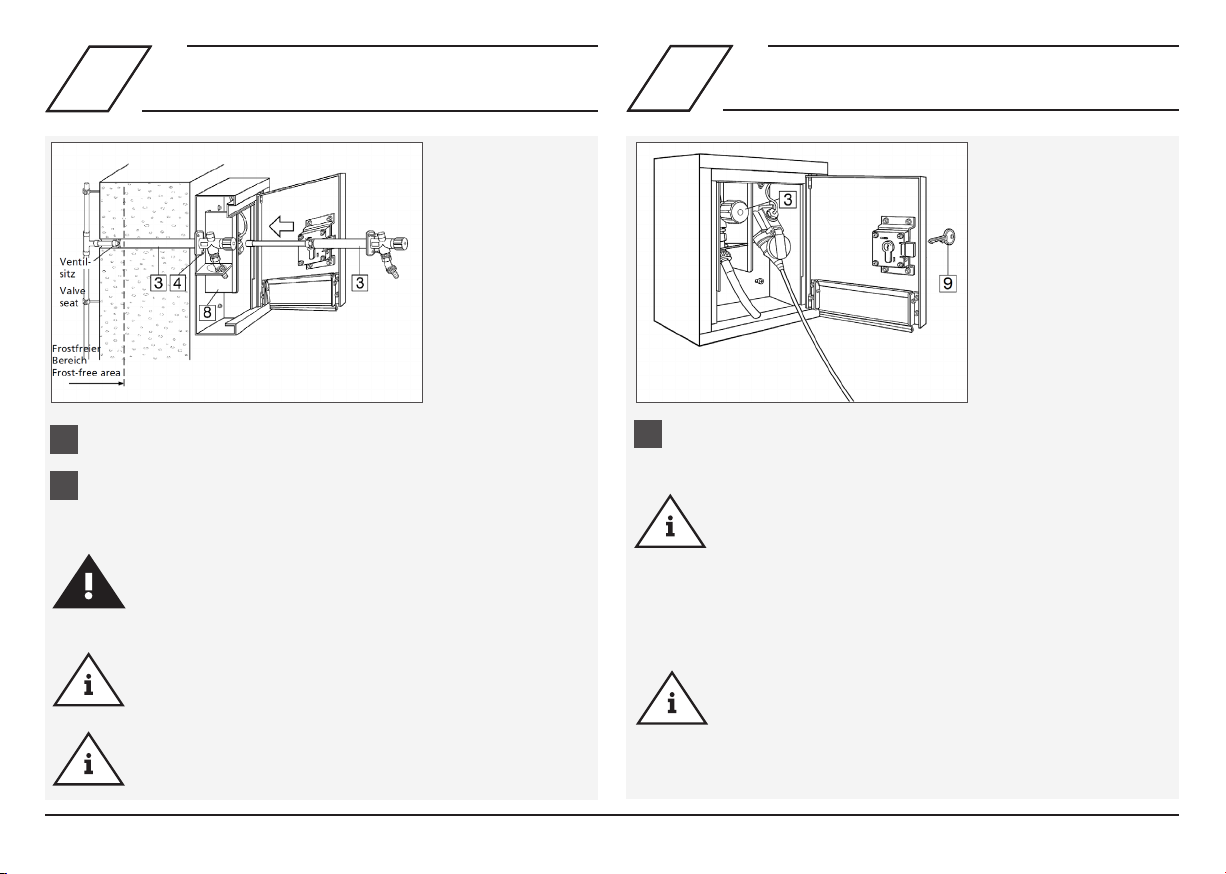
Hinweis!
Einbauort muss ein geschlossener,
trockener und frostfreier Raum sein, der nicht
überflutet werden kann.
Hinweis! V
or Abschluss der Montage unbe-
dingt eine Dichtigkeitsprüfung der wasserfüh-
renden Elemente sowie eine Funktionsprüfung
durchführen.
Haftung
Keine Gewährleistung oder Haftung bei:
- Nichtbeachten der Anleitung.
- fehlerhaftem Einbau und/oder Gebrauch.
- eigenständiger Modifikation am Produkt.
- sonstiger fehlerhafter Bedienung.
DE Sicherheitshinweise für Montage
Hinweis! Der gesamte Tresor ist
in regelmäßigen Abständen mit
einem Edelstahlreinigungsmittel zu
reinigen!
Pflege der Schrankoberfläche:
Aggressive und scheuernde Reini-
gungsmittel können die Oberfläche
beschädigen. Keine chlor- oder
säurehaltigen, schleifenden oder
ätzenden Reinigungsmittel verwen-
den. Die Reinigung wird mittels
feuchtem Mikrofasertuch empfoh-
len.
Hinweis! Die Elektro- und Sani-
tärinstallationen sind jeweils vom
Fachinstallateur auszuführen.
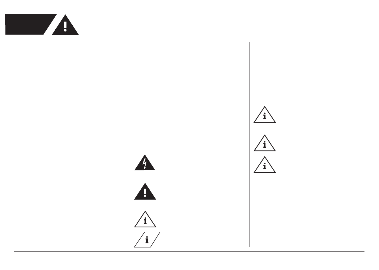
Hinweis! Das Sicherheitstürschloss
ist umrüstbar auf ein bestehendes
Schließsystem. Hierzu ist das Tür-
schloss auszutauschen.

3 / 12 – K410021200001-00 / 09.2021 – ©www.kemper-olpe.de
DE
Entsorgung
Örtliche Vorschriften zur Abfallver-
wertung bzw. -beseitigung sind zu
beachten. Produkt darf nicht mit
normalem Haushaltsmüll, sondern
muss sachgemäß entsorgt werden.
Bezeichnung
1
Wandaufputzschrank (Grundkörper)
2 4 Befestigungsschrauben und 4 Abstandshalter
3 Frostsichere Außenarmatur oder Geräteanschlussventil
4 2 Befestigungsschrauben (M6 x 12)
5 Steckdose (1 Stück)
6 Montageplatte
7 4 Schrauben für die Montageplatte und das Spritzschutzblech (M6 x 10)
8 Spritzschutzblech
9 Türschloss mit 3 Schlüsseln
Hinweis! Die Armatur muss min-
destens 250 mm über dem höchst-
möglichen Betriebswasserspiegel
eingebaut werden!
Hinweis! Die Verwendung als Ver-
teiler für Wasser und Strom ist nicht
in allen Ländern zulässig! Beachten
Sie eventuell bestehende landesspe-
zifische Regelungen, falls Sie beab-
sichtigen, den Verteiler außerhalb
Deutschlands zu verwenden.
Achtung! Lt. VDE-Bestimmungen
muss der KEMPER MINI-TRESOR
für Strom- und Wasseranschluss
durch einen FI-Schalter (Fehlerstrom
0,03A) abgesichert werden. Dies
gilt für alle Steckdosen im Außen-
bereich.
Hinweis! Bei Einbau des Tresors in
Schwimmbädern oder Einrichtungen
mit vergleichbaren Umgebungsbe-
dingungen, ist eine regelmäßige
Reinigung des gesamten Tresors,
wie vorher beschrieben, notwendig.

4 / 12 – K410021200001-00 / 09.2021 – ©www.kemper-olpe.de
2
Info!
Folgende Figuren werden mit der Schutzart IP 55
ausgeliefert:
21202015CH I 21209015CH
Hinweis!
Funktionsprüfung durchführen!
Gefahr!
Elektroarbeiten dürfen nur von autorisiertem Fachperso-
nal ausgeführt werden!
Montage Steckdosenkombination
und Spritzschutz
1.
2.
1.
2.
Stromzuführung vorsehen
- FI-Absicherung beachten:
Nennfehlerstrom ≤ 0,03 A,
Anschlussleistung ≤ 16 A und
Anschlussleitung 230 V
- Schutzart IP 44
Den Wandaufputzschrank an der Außenwand ausrichten und die
vier Bohrlöcher (Ø 8 mm) sowie die Bohrung für die frostsichere
Außenarmatur (Ø 27 mm) kennzeichnen und bohren.
Schrank (1) mittels beiliegenden vier Abstandshaltern und Befesti-
gungsschrauben (2) an der Außenwand befestigen.
Gefahr!
Erdung
Verbindung des Erdungskabels an der dafür vorgesehenen
Schraube im oberen Wandeinbauschrankbereich herstellen
(sämtliche metallischen Teile sind somit geerdet).
Steckdose 230 V (5) auf Montageblech (6) aufschrauben, im
Wandaufputzschrank (1) anschließen und mit den beiliegenden
Schrauben (7) an der Rückwand befestigen.
Das Spritzschutzblech (8) mittels beiliegenden Schrauben (7) senk-
recht zwischen Steckdose und Anschluss frostsicherer Außenarma-
tur an den vorgesehenen Befestigungspunkten an der Rückwand
anschrauben. (Das Spritzschutzblech kann auch nach Montage der
frostsicheren Außenarmatur angebracht werden.)
1Montage Wandaufputzschrank

5 / 12 – K410021200001-00 / 09.2021 – ©www.kemper-olpe.de
Hinweis!
Durch das selbständige Entleeren der Frostsicheren Au-
ßenarmatur (3) nach dem Zapfvorgang läuft das Wasser
nach dem Absperren für einige Sekunden nach (Frostsi-
cherheit). Es ist aus diesem Grunde nur leichtes Zudrehen
(Schließen) der Armatur erforderlich.
Hinweis!
Zur Sicherstellung der Funktion „Frostsicherheit“ müssen
Schläuche und sonstige Anbauteile vor Beginn der Frost-
periode entfernt werden!
1.
2.
1.
Hinweis!
Ventilsitz (Gewinde R ½“) muss im frostfreien Bereich
liegen.
Hinweis!
Die Mindestwandstärke von 180 mm Mauerwerk darf
nicht unterschritten werden (s. frostfreier Bereich).
Warnung!
Montage nur durch sachkundige, qualifizierte Fachkraft!
Funktionsprüfung der Frostsicheren Außenarmatur (3)
durchführen.
Frostsichere Außenarmatur (3) in die Bohrung stecken und mittels
der zwei beiliegenden M6-Schrauben (4) befestigen.
Außenarmatur (3) an die Wasserleitung anschließen
(Cu-Rohr Ø 15 mm oder AG R ½“).
3 4
Montage Frostsichere Außenarmatur Funktionsprüfung

6 / 12 – K410021200001-00 / 09.2021 – ©www.kemper-olpe.de
Use
The built-in wall cabinet serves as a supply
station for the central water and power supply.
Any other uses constitute misuse.
Connection options: e. g. water and power
connection for 230 V / 400 V, can be expan-
ded on site, e.g. by gas, telephone, antenna
or waste water connection, for private and
commercial use.
Warning information
Please read and follow the warning informati-
on in this instruction. Disregard of the warning
information may lead to injury or material
damage!
Labelling of important warning information:
Danger! Electricity!
Indicates hazards that might result
in severe or fatal injury.
Warning! Highlights risks that
may result in injury, material da-
mage or contamination of drin-
king water.
Note! Indicates hazards that may
lead to damages to the system or
malfunctions.
Info! Indicates additional infor-
mation and tips.
Important advice to the operator
Material: Stainless steel
Pressure rate valve: PN 16
Only use the TRESOR
- in sound condition
- as intended
Installation and operation
Read the manual carefully and follow the
instructions before installation!
Installation and maintenance must be
carried out by qualified plumbers.
Always pass on this manual to the current
system owner and keep it in a safe place for
future reference!
Warning! Priority must be given to the natio-
nal standards and provisions on sanitary
installations and accident prevention.
Warning! The installation location must be a
closed, dry and frost-free room that cannot be
flooded.
Warning! Before completing the installation,
it is essential to carry out a leak test of the wa-
ter-bearing elements as well as a functional test.
Warranty
Warranty or liability are voided through:
- Disregard of installation instructions.
- Damage due to faulty installation.
- Unauthorised product modifications.
- Other incorrect operation.
Precautions for installation
EN
Note! The door lock can be repla-
ced with an existing locking system.
The door lock must be replaced for
this purpose.
Note! The electrical and plumbing
installations must be carried out by
specialist installers.
Note! The complete Tresor must be
cleaned by a stainless steel cleaning
agent in regular intervals!
Care of the cupboard surface: Ag-
gressive and scour cleaning agents
can damage the surface. Don´t use
chloric or acidic, grinding or acidly
cleaning agents. Cleaning with a
damp micro-fibre cloth is recom-
mended.
Note! The valve must be attached
minimum 250 mm over the maxi-
mum of operating water surface.

7 / 12 – K410021200001-00 / 09.2021 – ©www.kemper-olpe.de
EN
Description
1
Surface-mounted wall cabinet (basic body)
2 4 attachment screws and 4 spacers
3 Frost-proof outer fitting or hose bibb
4 2 attachment screws (M6 x 12)
5 Socket (1 piece)
6 Mounting plate
7 4 Screws for mounting plate and spray protection plate (M6 x 10)
8 Spray protection plate
9 Door lock with 3 keys
Disposal
Local regulations on waste
recycling and disposal must be
followed. The product must not be
disposed of with household waste
but must rather be disposed of
appropriately.
Note! In some countries the use
of combination units with water
and electric is not permitted. Please
follow the specific regulations for
the relevant country, if you want
to install the product outside of
Germany.
Note! In case of assembly the
Tresor in swimming pools or faci-
lities with compareable ambient
conditions, a regular cleaning of
the complete Tresor is necessary as
described before.
Danger! According to VDE require-
ments KEMPER MINI-TRESOR for
power and water connection have
to fuse by a residual current circuit
breaker (residual current 0,03A).
This applies to all sockets in outdo-
or area.

8 / 12 – K410021200001-00 / 09.2021 – ©www.kemper-olpe.de
1.
2.
1.
2.
1 2
Installation of surface-mounted wall
cabinet
Installation of socket combination and
spray plate
Note!
Carry out a functional test!
Danger!
Electrical work must be carried out only by authorised
specialist personnel!
Info!
Following gures are delivered with protection type IP 55:
21202015CH I 21209015CH
Provide the power supply
- Note FI fuse:
Nominal fault current ≤ 0.03 A,
connection current ≤ 16 A and
connection voltage 230 V
- Protection type IP 44
Align the surface-mounted wall cabinet on the outer wall, and
mark and drill the four holes (Ø 8 mm) and the hole for the frost-
free outer fitting (Ø 27 mm).
Attach the cabinet (1) to the outer wall using the four spacers and
attachment screws (2).
Danger!
Earthing
Carry out connection of the earthing cable to the respec-
tive screw in the upper part of the wall-mounted box (thus
all metallic parts are earthed).
Screw the 230 V socket (5) onto the mounting plate (6), connect
in the surface-mounted wall cabinet (1) and attach to the cabinet
rear wall using the screws supplied (7).
Screw the spray protection plate (8) vertically between the socket
and the connection of the frost-proof outer fitting to the attach-
ment points provided on the rear wall, using the screws provided
(7). (The spray protection plate can also be fitted after the instal-
lation of the frost-proof outer fitting.)

9 / 12 – K410021200001-00 / 09.2021 – ©www.kemper-olpe.de
Conduct functional testing of the frost-proof outer fitting (3).
Note!
Due to the automatic draining of the frost-proof outer
fitting (3) after removal of water, water will continue
to drain out for a few seconds after closing the fitting
(frost safety). For this reason, the fitting only needs to be
closed gently.
Note!
To ensure the correct ‘frost safety‘ function, hoses and
other attachements must be removed before the start of
the frost period!
1.
2.
1.
4Functional testing
3Installation of frost-proof outer fitting
and spray protection
Insert the frost-proof outer fitting (3) into the hole and attach
using the two M6 screws (4) provided.
Connect the outer fitting (3) to the water supply
(copper pipe Ø 15 mm or AG R ½“)
Note!
The valve seat (thread R ½“) must be located in the frost-
free area.
Note!
The masonry must be at least 180 mm thick (see frost-
free area).
Warning!
Installation must be carried out by qualified plumbers!

10 / 12 – K410021200001-00 / 09.2021 – ©www.kemper-olpe.de

11 / 12 – K410021200001-00 / 09.2021 – ©www.kemper-olpe.de

K410021200001-00 / 09.2021
Service-Hotline +49 2761 891-800
www.kemper-olpe.de
info@kemper-olpe.de
i
i
Gebr. Kemper GmbH + Co. KG
Harkortstraße 5
D-57462 Olpe
12 / 12 – K410021200001-00 / 09.2021 – ©www.kemper-olpe.de
Other manuals for MINI-TRESOR
4
Table of contents
Languages:
Popular Power Supply manuals by other brands

Analytic Systems
Analytic Systems PWS1000-110-12 Installation & operation manual

Texas Instruments
Texas Instruments TIDA-050034 Design guide

Seneca
Seneca Z109S-1 manual

Plantronics
Plantronics EU POWER SUPPLIES Declaration of conformity

Wheelock
Wheelock POWERPATH PS-12-24-8 installation instructions

Keysight Technologies
Keysight Technologies N6900 Series Operating and service guide