Turning Grill Off
•Turn all knobs to OFF position.Turn LP tank off byturning
OPD handwheel clockwise to a full stop.
Ignitor Check
•Turn gas off at LP tank. Press and hold ignitor button. "Click"
should be heard and spark seen each time between collector
box or burner and electrodes. See "Troubleshooting" if no click
or spark.
Valve Check
•important: Make sure gas is off at LP tank before checking
valves. Knobs lock in OFF position. Tocheck valves, first
push in knobs and release, knobs should spring back. If knobs
do not spring back, replace valve assembly before using grill.
Turn knobs to LO position then turn back to OFF position.
Valves should turn smoothly.
General Grill Cleaning
•Keepthe outside of your grill looking new by cleaning it once a
month with warm soap and water or a non-abrasive cleaner. If
you don't havea grill cover, wipe off dust and grime before
starting your grill.
• Coating the cooking gridswith spray-on cooking oil will keep the
food from sticking and make clean up easier.After cooking,
scrape the grates with a long handled, brass wire bristle brush.
•Check inside the grill bottom for grease build upand clean
often, especially after cooking fatty meat.
•Do not mistake brown or black accumulation of grease and
smoke for paint. Apply a strong solution of detergent and water
or use a grill cleanerwith scrub brush on insides of grill lidand
bottom. Rinse and allow to completely air dry. Do not apply a
caustic grill/oven cleanerto painted surfaces.
•Plated wire grates: Wash grates with concentrated grill
cleaner or use soap and water solution. Dry thoroughly and
store indoors between cookouts.
• Plastic parts: Wash with warm soapy water and wipe dry.
,A. Do not use citrisol, abrasive cleaners, degreasers or a
concentrated grill cleaner on plastic parts. Damage to and
failure of parts can result.
•Porcelain grates: Because of glass-like composition, most
residue can be wiped away with baking soda/water solution or
specially formulated cleaner. Use non-abrasive scouring
powder for stubborn stains.
•Painted surfaces: Wash with mild detergent or nonabrasive
cleaner and warm soapy water.Wipe dry with a soft
nonabrasive cloth.
•Stainless steel surfaces: Tomaintain your grill's high quality
appearance, wash with mild detergent and warm soapy water
and wipe drywith a soft cloth after each use. Baked-ongrease
deposits may require the use of an abrasive plastic cleaning
pad. Use only in direction of brushed finish toavoid damage.
Do not use abrasive pad on areas with graphics.
• Cooking surfaces: If a bristle brush isused to cleanany of
the grill cooking surfaces, ensure no loose bristles remain on
cooking surfaces prior to grilling. It is not recommendedto
clean cooking surfaces while grill is hot.
cAuT,o.
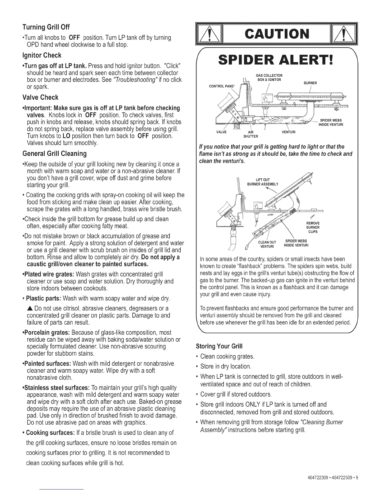
SPIDER ALERT!
GAS COLLECTOR
VALVE AIR VENTURI
SHUTTER
Ifyou notice thatyour gri// is getting hard to light or that the
flame isn't asstrong as itshou/d be,take the time to checkand
dean theventuri's.
LIFTOUT
BURNERASSEMBLY
REMOVE
BURNER
CLIPS
CLEANOUT SPIDER WEBS
VENTUR] INSIBEVENTURI
Insomeareasofthecountry,spidersor smallinsectshavebeen
knowntocreate"flashback"problems.Thespidersspinwebs,build
nestsandlayeggsin thegrill'sventuritube(s)obstructingtheflowof
gastotheburner.Thebacked-upgascanignitein theventuribehind
thecontrolpanel.Thisis knownasa flashbackanditcandamage
yourgrilland evencauseinjury.
Topreventflashbacksandensuregoodperformancetheburnerand
venturiassemblyshouldberemovedfromthegrilland cleaned
beforeusewheneverthegrillhasbeenidleforanextendedperiod.
,,. j
Storing Your Grill
• Clean cooking grates.
• Store indry location.
• When LP tank is connected to grill, store outdoors in well-
ventilated space and out of reachof children.
• Cover grill ifstored outdoors.
• Store grill indoors ONLYif LP tank is turned off and
disconnected, removed from grill and stored outdoors.
• When removing grill from storage follow "CleaningBurner
Assembly" instructions before starting grill.
464722309,464722509.9