7 Wire, 2 Stage Cooling, 2 Stage Heat
Commercial Gas or Electric Heat *,
Electric Cool, split systems & package units,
inctudin( Commercial Heat Pumps **
ic 0 :_
i E :3
i C If using a Residential heat pump,
this option must be set to ON :_
i C duringAdvancedSetup. :_
i E
i c --
ic
i c
i c
ic
i c
ic 0
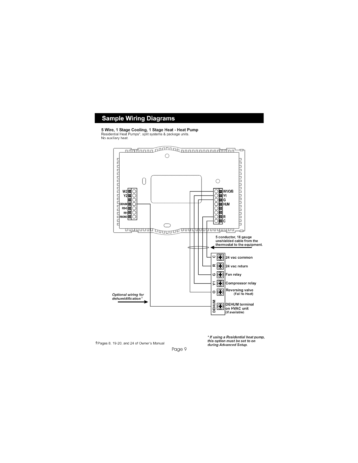
Optional wiring for
dehumidification _ID
3
03
Y1 3
3
18 g_uge
I I unshielded cable from the
9{ t2mostat to the equipment.
I, .v cc.....
L_ 24 vac return
m
m
L
.9 [] Fan relay
-[] Compressor relay
_. [] 1st stage heat circuit
_. [] 2nd stage
heat circuit relay
[] 2nd stage
compressor relay
i[] DEHUM terminal
on HVAC unit
3[if available)
tPages 8, 19-20, and 24 of Owner's Manual
Page 8
*If using electric heat this option must
be set to ON during Advanced Setup,
** Commercial heat pumps do not have
the heat pump turned on in Advanced Setup.