Kenmore 105.20001410 User manual

Use & Care Guide
Model: 105.20001410
P/N XXXXXXXXX
Sears Brands Management Corporation,
Hoffman Estates, IL 60179
www.ken more.coB
www.sears,com
www.kmart.com

ASSURELINK INFORMATION - WARRANTY
IMPORTANT SAFETY INSTRUCTIONS
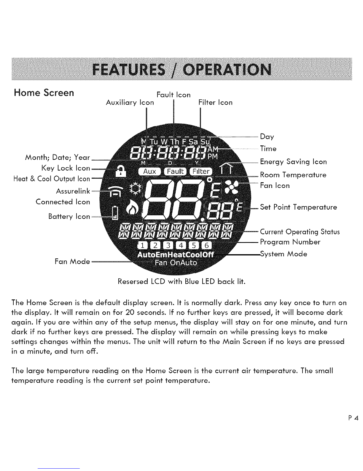
FEATURES/OPERATIONS
CLEANING /MAINTENANCE INSTRUCTIONS
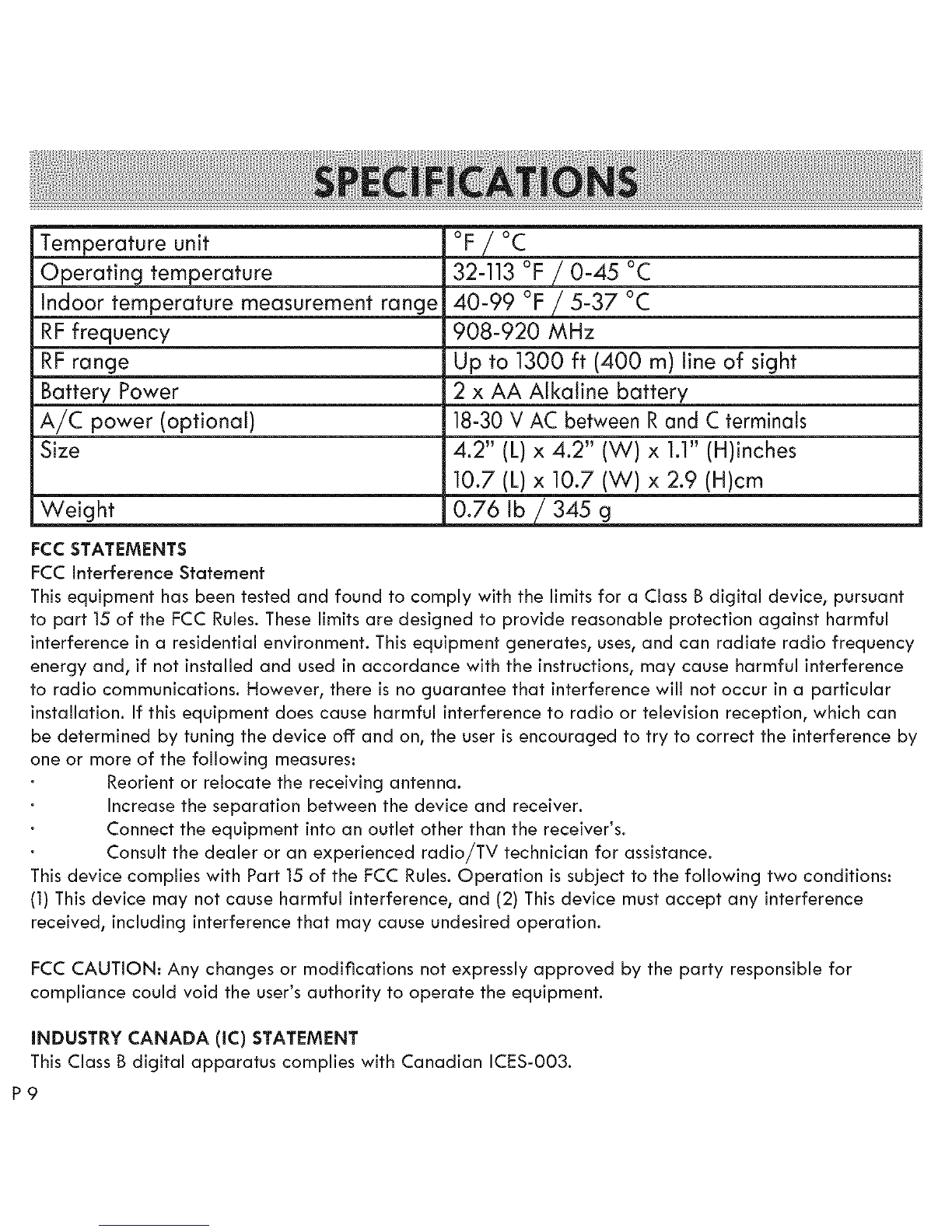
SPECIFICATIONS /FCC INFORMATION
TROUBLESHOOTING
FAQ
P1
P2
P3
P8
P9
P10
Pll
Refer to the Quick Start /Installation Guide that came with your I<enmore Smart Thermostat for detailed
installation instructions. Also refer to it for information on creating an Assurelink Connected account,
setting up your gateway, and setting up your thermostat for connected operation from your phone or web
browser. This Use & Care Guide contains more detailed information, and instructions for operating the
Thermostat from the front panel controls.
KENMORE LIMITED WARRANTY
FOR ONE YEAR from the date of sale this product is warranted against defects in material or workmanship when it is correctly
connected, operated and maintained according to all supplied instructions.
WITH PROOF OF SALE, return a defective product to the retailer from which it was purchased for free replacement.
This warranty is void if this product is ever used for other than private household purposes.
This warranty covers ONLY defects in material and workmanship, and will NOT pay for..
1. Damage to or failure of this product if it is not correctly connected, operated or maintained according to all supplied instructions.
2. Damage to or failure of this product resulting from accident, alteration, abuse, misuse or use for other than its intended purpose.
3. Damage to or failure of parts or systems resulting from unauthorized modifications made to this product.
Disclaimer of implied warranties; limitation of remedies
Customer's sole and exclusive remedy under this limited warranty is product replacement as provided herein. Implied warranties,
including warranties of merchantability or fitness for a particular purpose, are limited to one year or the shortest period allowed by
law. Seller shall not be liable for incidental or consequential damages. Some states and provinces do not allow the exclusion or
limitation of incidental or consequential damages, or limitation on the duration of implied warranties of merchantability or fitness, so
these exclusions or limitations may not apply to you.
This warranty gives you specific legal rights, and you may also have other rights which vary from state to state.
Sears Brands Management Corporationt Hoffman Estatest IL 60179

When using your equipment, basic safety precautions should always be followed to reduce risk of
fire, electric shock, and injury to persons,including the following:
1. Readall of the instructionslisted hereand/or in the usermanualbefore youoperate the device. Give
particular attention to all safety precautions.Retainthe instructionsfor future reference.
2. Thisdevice mustbe installed and usedin strict accordance with the installation manualand/or useand
care guide.
3. Complywith all warning and caution statementsin the instructions.
4. Thethermostatcan be powered by two AA batteriesor by a connectionto a 24VAC power source
(C-wire).Always installthe 2 AA batteriessothat they will runthe Smart Thermostatin caseof a power
failure.
5. Never connectany terminal of the thermostatto 120/220V AC; this may causeseriousdamage to the
thermostatand evenyour HVAC system.
6. Do notinstall this thermostatat an altitude of over 6500 feet (2000 meters).
7. Thisstandalone mountedelectronicthermostatservesas a temperature control systemonly in dry,
closed living or office spaces.Do not place it in a bathroom or area of excessivemoisture.Do not allow
it to get wet.
8. Thisdevice shouldnot be usedin an environmentthat isbelow 32°F (0°C) and above 104°F(50°C),
humidityabove 80%.
9. Donot exposethe thermostatto voltage fluctuationsof morethan+/-10%.
10. Cleanthe thermostatwith a dry, soft cloth. Do not usesolventsor aggressivecleaning agents.NEVER
usedetergents,gasoline,glasscleaner, furniture polish,paint thinner, or other householdsolventsto
clean any part of the thermostat.
11. Never place anythingover the air ventsof the thermostat.
12. Never drop any liquid or chemical insideof the thermostatthroughthe air vents.
13. DO NOT useoutdoors.
14. DO NOT attempt to repair or adjust any electronic or mechanicalfunctionson this thermostat. Doingso
will void yourwarranty. Theinsideof the unitcontainsno userserviceableparts.
NOTE: DO NOT Block air vents of the thermostat.
NOTE: incorrect connection of HVAC wires to thermostat terminals may cause unrecoverable damage to
your HVAC system, incorrect wiring connection voids all thermostat warranty coverage. Nor is thermostat
seller or manufacturer responsible for any HVAC system damage due to incorrect wiring connection.

Back Up Key
Menu or Down Key
Fan System
Reset Button (located at the bottom part of the Kenmore Smart Thermostat)
KEY/TOUCH ACTION
Up Key
Down Key
System Key
Fan Key
Menu /Select Key
Back Key
Reset Button
FUNCTION
Increase set temperature for TEMP HOLD or PERM HOLD. Also used with DownNkey to
activate "Key Lock"
Decrease set temperature for TEMP HOLD or PERM HOLD. Also used with Up key to activate
"Key Lock"
Switching operating mode: AUTO, HEAT,COOL, OFF, & EMERGENCYHEAT
Switching fan mode: ON or AUTO
PressMenu /Select once and use Up/Down Key to navigate the following functions:
• Vacation • Clock • Program • Settings • Filter
• When the thermostat shows the function you want to set up, press Menu/Select once again
to enter that function.
• For modifying parameters, use Up/Down to change and Menu/Select to confirm the setup value.
• At any time during Setup, pressing Back once will navigate backward one level and cancel
any setting change you have made.
• Pressing and holding Back for 2 seconds while in a Menu screen will return the unit to the
Home Screen.
Pressing and holding Back for 2 seconds while on the Home Screen will cancel Temp Hold,
Perm Hold, Vacation mode, and Away mode. (Away mode is only available via the
Assurelink remote APP.)
Reset the thermostat. Can also used for installation setup and to remove the
thermostat from customer's Assurelink account. See Assurelink APP for details.

Home Screen Fault Icon
Auxiliary Icon Filter Icon
Month; Date; Year_
Key Lock Icon
Heat & Cool Output Icon
Assurelink
Connected Icon
Battery Icon
Fan Mode
Resersed LCD with Blue LED back lit.
Day
Time
Energy Saving Icon
Room Temperature
Fan Icon
Set Point Temperature
Current Operating Status
Program Number
System Mode
The Home Screen is the default display screen. It is normally dark. Press any key once to turn on
the display. It wiii remain on for 20 seconds. If no further keys are pressed, it wiii become dark
again. If you are within any of the setup menus, the display wiii stay on for one minute, and turn
dark if no further keys are pressed. The display wiii remain on while pressing keys to make
settings changes within the menus. The unit wiii return to the Main Screen if no keys are pressed
in a minute, and turn off.
The large temperature reading on the Home Screen is the current air temperature. The small
temperature reading is the current set point temperature.

Quick Change of Set Temperature for Temporary Hold and Permanent Hold
To increase the temperature, press Up when the thermostat is on the Home screen. To decrease
the set temperature, press Down. Pressonce for each degree of temperature change.
The latest set temperature will be stored and held until the next scheduled temperature change.
This wiii be displayed as TEMP HOLD. To make the adjusted setting permanent, press and hold
the Up or Down key for two seconds or until the display says PERMHOLD. To exit from TEMP or
PERMhold, press and hold the BACK key for 2 seconds, the thermostat wiii return to the
programmed schedule mode, displayed as SCHEDULE.
Set Heat/Cool Mode
When you are on the Home screen, press System to change the HVAC system mode to one of
the following:
Auto, Heat, Cool, Off or Emergency Heat (for Heat Pump systems)
Set Fan Mode
When you are on the Home screen, press Fan to change Fan mode to one of the following:
Fan On, or Fan Auto
When the fan is running, the Fan icon will show in the display.
Setup Menu
PressMenu / Select, then press up or down to select one of the following setup functions:
Vacation
Clock
Program
Settings
Filter
Vacation
Enter Vacation setup by pressing Menu /Select. Once within Vacation setup, set the start date
by entering Month, Day and Year. Use Up/Down to change the value and press Menu / Select
to confirm each. Similarly, set up the end date. The thermostat wiii also ask to set up the
temperature during vacation. For example, during winter, you can set to a low temperature such
as 55 ° F, to prevent house water pipes from freezing.

Clock
EnterClockSetupbypressingMenu/Select.SettheTimeZonewiththeUp&Downkeys.Press
Menu/Selecttoconfirm.Thenselect12Hror24HrClockViewwiththeUp& Downkeys.Press
Menu/Selecttoconfirm.ContinuetousethesamemethodtoselecttheHour,Minute,Month,
Day,Year,andtochooseDaylightSavingsTimeOn or Off. PressMenu/Select to confirm, and
Back to exit.
Program
There are three types of programming modes:
5/2 (Weekday and Weekend) schedule
All days the same
7days individual schedule
Enter Program setup by pressing Menu /Select. Once within the Program menu, you have to
select the mode. Initially, "M Tu W Th F" will flash on the screen. If you press Menu /Select to
confirm, you are selecting the 5/2 days mode. You will be asked to set up the Time, Heat Set
point and Cool Set point for six time periods within the day. Once the five weekdays are set, you
will be asked to input the weekend schedule programs.
If you would like to set up all seven days the same, skip the flashing "M Tu W Th F" and "Sa Su"
by pressing Up. You will see all seven days "M Tu W Th F Sa Su" flashing together. You can
confirm by pressing Menu /Select, and start to input the six time periods within the day.
If you would like to have seven days of individual programming, skip the all days the same setup
and confirm with individual day. You have to set up each day one by one with the same proce-
dure.
Hint: To set up less than 6specific periods, simply set up 2 or more periods the SAME. The
identical periods will act as one period. Also, the thermostat will only allow you to set up periods
that are at least one hour apart.
Settings
Enter Settings setup by pressing / Menu Select. Use to access the settings of the thermostat
functions. There are five functions under Setting that can be navigated using the Up and Down
buttons:

DisplayInstallationsetup
ThismenuwiiishowthecurrentHVACsystemsettingthatwassetupduringinstallation.It
shoulddisplayoneofthefollowing:
NHP-HE-C
NHP-HG-C
NHP-HE-NC
NHP-HG-NC
HP-O
HP-B
(Electricheatwithairconditioning)
(Gasheatwithairconditioning)
(Electricheatwithoutairconditioning)
(Gasheatwithoutairconditioning)
(HeatPumpwith0reverse valve)
(Heat Pump with B reverse valve)
Set Temperature Unit in °F or °C
Use Up or Down to select °F or °C for all temperature displays. PressMenu Select to confirm
the selection.
Set Temperature Offset
The Kenmore Smart Thermostat has been factory calibrated so you usually do not need to set
any temperature offset. However, in some rare situations you find that the temperature is not
accurate enough, you can use this function to offset the displayed temperature from -7°F to
+7°F (-4°C to +4°C).
Set Auto Recovery
For multi-stage systems, the thermostat supports an auto recovery algorithm when there is any
set point change scheduled. If enabled, it wiii turn on the HVAC system earlier to avoid the
HVAC system needing to turn on a second or higher stage. This permits a gradual change of
temperature before the set time, rather than a sudden change at the set time. Under this menu,
you can select YESor NO to enable or disable auto recovery function.
Set Span and Dead Band of thermostat control
There are two key parameters for thermostat control: Span and Dead Band.
The Span defines the maximum possible range of the temperature variance from the set
temperature. For example, if you set the temperature to 70°F and set Span to I°F, the
temperature wiii swing from 69 ° Fto 71°F. The Span setting range is from 0.5°F to 2°F (0.25°C
to 1°C).

DeadBandisusedforautomaticallychangingtheHVACsystemmodesfromHeattoCoolor
CooltoHeat.Iftheroomtemperaturekeepsgoingintheoppositedirectionfromthecurrent
modeandexceedstheDeadBandtemperature,theI<enmoreSmartThermostatwillautomati-
callyswitchtothealternatemode.Example:TheDeadBandissetto5° Fand the thermostat is
set to Cool mode at 70°F. If the room temperature drops down to 65°F, the system will switch
from Cool to Heat mode. The I<enmore Smart Thermostat can set the dead band from 2°F - 5°F
(2.5°C - 6°C).
Filter
Enter Filter setup by pressing Menu /Select.
You can set the number of hours before the thermostat will remind you to install a new filter.
There is a selection for 300, 500 and 700 hours. You can also reset the count to zero when you
change the filter.
Key Lock
To lock the keys and prevent them from being used, hold Up and Down together for 2 seconds.
A lock icon will appear. To unlock the keys for use, repeat the same process, the lock icon will
disappear.
Remove Thermostat from Customer Assurelink Account
Pressthe Reset button on the bottom of the thermostat with a paper clip. When all the icons are
visible on the screen, press Up & Down for 2 seconds. Use the Up and Down keys to select the
"Yes" or the "No". Now press Menu/Select. If you selected "No", the thermostat wiil return to the
Main Screen. If you selected "Yes*',the "ReqDelete" screen wiil appear for 3 seconds, then the
Main Screen will return. The thermostat has been removed from the customer's online Assurelink
account.
When the low battery icon is ON, replace the batteries immediately. Don't leave any used up
battery in the thermostat. The chemical leakage of drained batteries may damage the thermo-
stat and cause it to malfunction.

Temperature unit
Operating temperature
indoor temperature measurement range
RF frequency
RF range
Battery Power
A/C power (optional)
Size
Weight
FCC STATEMENTS
FCC interference Statement
OF/°C
32-113 OF/0-45 °C
40-99 °F /5-37 °C
908-920 MHz
Up to 1300 ft (400 m) line of sight
2 x AA Alkaline battery
18-30 V AC between Rand C terminals
4.2" (L) x 4.2" (W) x 1.1" (H)inches
10.7 (L) x 10.7 (W) x 2.9 (H)cm
0.76
This equipment has been tested and found to comply with the limits for a Class Bdigital device, pursuant
to part 15of the FCC Rules. These limits are designed to provide reasonable protection against harmful
interference in a residential environment. This equipment generates, uses, and can radiate radio frequency
energy and, if not installed and used in accordance with the instructions, may cause harmful interference
to radio communications. However, there is no guarantee that interference will not occur in a particular
installation. If this equipment does cause harmful interference to radio or television reception, which can
be determined by tuning the device off and on, the user is encouraged to try to correct the interference by
one or more of the following measures:
Reorient or relocate the receiving antenna.
Increase the separation between the device and receiver.
Connect the equipment into an outlet other than the receiver's.
Consult the dealer or an experienced radio/TV technician for assistance.
This device complies with Part 15 of the FCC Rules. Operation is subject to the following two conditions:
(1) This device may not cause harmful interference, and (2) This device must accept any interference
received, including interference that may cause undesired operation.
FCC CAUTION: Any changes or modifications not expressly approved by the party responsible for
compliance could void the user's authority to operate the equipment.
INDUSTRY CANADA (IC) STATEMENT
This Class B digital apparatus complies with Canadian ICES-003.
P9

TROUBLE
o No Display when
touching the keys
PROBABLE CAUSE SOLUTION
Batteries are depleted
For 24 VAC connected
thermostat, the RH!RC or C
cable may be disconnected.
Furnance turned off.
_/Replace the batteries
_/Check the connections and correct them
_/Turn the HVAC system back on.
. Low battery icon is _Battery level low _/Replace the batteries
ON
"No Assurelink icon
displayed, or can't
control the thermo-
stat through the
smart phone App
• Filter icon is ON
" Room temperature
showing H or L
instead of digits
"Can't use the touch
keys when the home
screen is showing
Can't connect to cloud server
RF signal can't reach the
thermostat
•- Filter life expired
The HVAC system may
turn OFF under an
extreme high or low
temperature environ-
ment.
The unit has been set to
Key-Lock
The mode of operation
is not selected according
to the season. For
example, selecting Heat
mode in summer.
°The HVAC system
stopped regulating
the temperature
with the set point
_/Check the Gateway Ethernet connection
_/Check the availability of Internet access
_/Move the Gateway closer to the thermostat
,J Change filter then reset the filter counter.
Refer to the Filter section under
Feature/Operation.
_/Turn ON the HVAC system with the thermostat
and wait for about 15-30 minutes; it should
display the room temperature again. If the
environment temperature is not normal, call for
service for your HVAC system.
_/To release the Key-Lock, press Up and Down
together for about 2-3 seconds. To activate
the Key-Lock, press Up and Down together
for about 2-3 seconds.
_/Manually change the operating mode by
pressing System button. You can also select
Auto so the thermostat will determine for you
the mode of operation automatically.

QUESTION
.How can the thermostat help to
save energy?
.Shall I change Heat/Cool mode
manually?
.How to select the filter time?
"Can I prevent children from
changing the set temperature
accidentally?
ANSWER
_/Use the Schedule Program to set the temperature that consumes
less energy. For example, lower the temperature in winter
during a period in the days that your family is usually not at
home.
_/Turn OFF the heating and/or cooling through your App.
Don_t forget to turn it back on.
_/You can manually select Heat or Cool mode for the HVAC
system. However, you can also select Auto so the thermostat
will determine for you the mode of operation automatically.
_/Refer to the filter description. It depends on the filter type. You
can set 300, 500, 700 of fan operation at the thermostat.
_/You can lock the keys by holding Up and Down key together
for about 2-3 seconds.
.Can the thermostat display in _/Yes, through Menu Select and Up/Down key, select SETTING >
Celsius instead of Fahrenheit? TEMP UNIT > C.
.Can I use the thermostat for heat
pump HVAC System? _/Yes, the thermostat supports all common type heat pump HVAC
systems. Installer will setup the appropriate system for you
under installation mode. Please refer to Installation Manual.

WIRING DIAGRAM
Wiring Diagram for Conventional Heat Cool Single Transformer System
ZI_I heatii_j uelay
Fa. ,elay
_ Juraper wire
24VAC
Wiring Diagram for Conventional Heat Cool Two Transformer System
21_dheafiaq relay
Fal_ relay
E
2,_11i__
_,vAc_lJ___

Wiring Diagram for Floor Heating System
Z1_dheati_gleh_y
Fall lelay
_Jumper wire
Floor He_ting
t_a_f_rme_
Wiring Diagram for Heat Pump Single Transformer S,,stem
oiB rel_y
1_tAU×heat_._rel_y
F.,., elry
)Jumper wire

Wiring Diagram for Heat Pump with two Transformer System
o,e ,eJ_,y
_n,iC_mp,es_ol le_y
F_I,relay
MCU {_
Cool_n_ T[_n_forrner
1Iv

Terminal Definition
illZHI
Re _;_
RH
LoE
YI _
Terminal
HP
RC
RC
C
L
YI
Y2
Wl
oiB
G
×
Terminal
Non-HP
RC
EH
Heat Pump
System Conventional System
24VAC Power supply for Cooling side
24VAC Power supply for Heating side
2,4 MAC common for control circuit and
thermostat power input
System Monitor
1_ stage
camp FeSSQ r
2 nd stage
comp FeSSQ r
Y1
Y2
Wl Emergency Heat
W2 Chartgeover va lye
G Fan
XReserve for future using
No use
1_ stage cooffn 9
2"a stage cooling
1_ stage heating
2.d stage heating
Other manuals for 105.20001410
1
Table of contents
Other Kenmore Thermostat manuals
Popular Thermostat manuals by other brands

Termoventiler
Termoventiler Thermomatic EC Home Quickstart Guide for installation and first start-up

Technoline
Technoline TM 3050-RF user guide

Master cool
Master cool MasterStat CC2000B Specification sheet

Isotech
Isotech ITL-M-18233 User maintenance manual/handbook

Pro 1 IAQ
Pro 1 IAQ T631W-2 operating manual

EQ3
EQ3 MAX! Radiator Thermostat+ operating manual