1. Brief Introduction
The S-MIX-PRO1600 is a new, single-card, single signal port, high-definition seamless hybrid matrix
that supports a total of 16 high-definition video. Among them, 16 channels can be customized as
input/output mode, which can automatically detect the card type and support the asymmetrical
configuration of input/output channels. The system supports HDMI, DVI, VGA, SDI, YPBPR, CVBS,
HDBaseT, H.264, HDCI, Fiber and other signals, and can customize the output resolution, up to
3840*2160@30Hz. At the same time, the system uses a seamless switching technology, there is no
black screen, blue screen, tearing, jitter and other phenomena in the switching process. At the same time
also supports 15 wall display. Can be widely used in government, justice, military, education, medical,
corporate and other occasions.
2. Product Features
> Support 16-channel mufti-type video interface, any configuration for input or output, 16-way arbitrary
combination;
> Single-card single signal port design, configuration and maintenance more flexible;
> Built-in board intelligent identification technology, automatic detection of card type, plug and play;
> Support input signals: HDMI, DVI, SD/HD/3G-SDI (Adaptive), VGA, YPBPR, CVBS, HDBaseT, H.264,
Fiber, HDCI (Poly com video conferencing terminal dedicated interface)
> Support output signal: HDMI, DVI, VGA, Fiber YPbPr, CVBS, HDBaseT, H.264, HDCI (Poly com video
conferencing terminal dedicated interface)
> Support output resolution custom adjustment, up to 3840*2160@30Hz;
>Using seamless switching technology, there are no black screens, blue screens, tearing, jitter, etc.
during the switching process;
> Support EDID management, compatible with HDCP protocol
> Support subtitles logo function
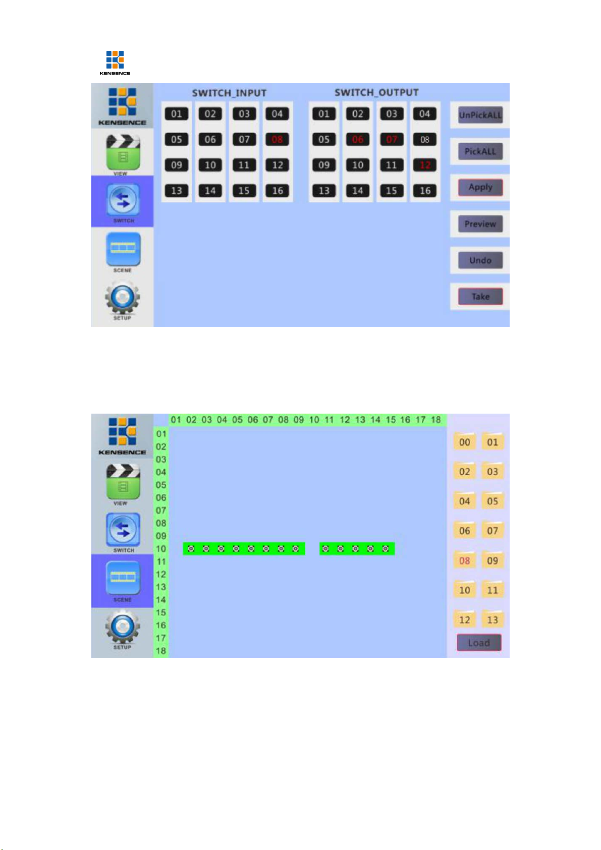
3. Connection and operation
1. Connect signal source such as Blu-ray player , game controller, A/V receiver, cables, satellite