KENT USA TRD1230 User manual

RADIAL DRILLS
TRD1230 TRD1230H
TRD1600H TRD2000H
Operation Manual
Property of KENT Industrial USA
Do Not Reproduce

page
0-1
Section Content
CHAPTER 1 Safety Guidelines
1.1 Please follow the below basic safety principles ……………………….. 1-1
1.2 Precautions for the transportation and installation …………………….. 1-1
1.3 Precautions for operation …………………………………………….. 1-1
1.4 Precautions for checking and maintenance …………………………….. 1-2
1.5 Warning labels on the machine …………………………………………. 1-3
1.5.1 Warning labels and mark introduction……………………………………….. 1-3
1.5.2 Labels ………………………………………………………………………. 1-4
CHAPTER 2 General specifications
2.1 The anticipated machine life ……………………………………………. 2-1
2.2 Machine dimensions ……………………………………………………. 2-1
2.3 The machine …………………………………………………………………. 2-2
2.3.1 Description …………………………………………………………………. 2-2
2.3.2 Parts …………………………………………………………………………. 2-2
2.4 Specifications ………………………………………………………………... 2-3
……………………………………………….. 2-3
……………………………………………….. 2-4
……………………………………………….. 2-5
2.4.1 TRD-1230H Specification
2.4.2 TRD-1230 Specification
2.4.3 TRD-1600H Specification
2.4.4 TRD-2000H Specification …………………………………………. 2-6
2.5 Standard and Option Accessories …………………………………………. 2-7
2.6 Operation position and noise level …. ……………………………………... 2-7
2.6.1 Operation position …………………………………………………….. 2-7
2.6.2 The noise level ……………………………………………………………. 2-7
CHAPTER 3 Preparation to install
3.1 Space and room requirement …………………………………………….. 3-1
3.1.1 Floor requirement ………………………………………………………… 3-1
3.1.2 Space requirement ………………………………………………………… 3-3
3.2 Environment requirement ……………………………………………… 3-3
3.3 Power supply requirement ……………………………………………… 3-4
3.4 Electric system alculation ……………………………………………… 3-5
CHAPTER 4 Transportation and Installation
4.1 Disassembly and packaging ……………………………………………. 4-1
4.1.1 General ……………………………………………………………….…… 4-1
4.1.2 Packaging …………………………………………………………………. 4-1
4.2 Transportation ……………………………………………………………... 4-2
4.2.1 The diagram of the machine weight and its gravity center ……………. 4-2
Property of KENT Industrial USA
Do Not Reproduce

page
0-2
Section Content
4.2.2 The movement of the machine ………………………………………… 4-2
4.2.3 The order to pack …………………………………………………………... 4-3
4.3 Installation of the machine ……………………………………………… 4-3
4.3.1 Have the machine set onto the fastening bolts of the crate base ………. 4-3
4.3.2 Level adjusting. ……………………………………………………………. 4-4
4.3.3 The installation of the electricity ……………………………………… 4-4
4.4 The test after installation ……………………………………… 4-4
4.5 The procedure for dismantling the machine ………………………….. 4-4
CHAPTER 5 Operation
5.1 A brief introduction to the relevant operation hardware ………………. 5-1
5.1.1 (For TRD-1230, TRD-1230H) ……………………………………….. 5-1
5.1.2 (For TRD-1600H, TRD-2000H) ……………………………………... 5-3
5.1.3 Safty protective device (suit every model)…………………………….……. 5-5
5.2 Instruction to switches ………………………………………………….. 5-6
5.2.1 (For TRD-1230, TRD-1230H) ………………………………………… 5-6
5.2.2 (For TRD-1600H, TRD-2000H) ………………………………………… 5-8
5.3
Installation of the clamp(work piece)………………………………. 5-9
5.3.1 General ……………………………………………………………………. 5-9
5.3.2 Introduction of the vise and the clamping of the work piece ………… 5-9
5.3.3 Universal clamp and the clamping of the work piece ……………….. 5-10
5.4 Installation and change of the drilling bit …………………………… 5-11
5.4.1 The assembly and disassembly of the drilling head and clamp ……… 5-11
5.4.2 The assembly and disassembly of the straight handle drill bit ……….. 5-13
5.5 Power on and off …………………………………………………………... 5-13
5.5.1 Power on …………………………………………………………………... 5-13
5.5.2 Power off …………………………………………………………………... 5-13
5.6 Work light …………………………………………………………………. 5-14
5.7 Cutting fluids ……………………………………………………………... 5-14
5.8 Elevating the arm …………………………………………………………... 5-14
5.9 Rotate the Gearbox right or leftwards ………………………………… 5-15
5.9.1
(For TRD-1230,TRD-1230H)………………………………….. 5-15
5.9.2
For TRD-1600H, TRD-2000H)……………………………………… 5-15
5.10 Rotate the arm forward or backwards ………………………………… 5-16
5.10.1 (For TRD-1230,TRD-1230H)……………………………………………….. 5-16
5.10.2 (For TRD-1600H, TRD-2000H)……………………………………………... 5-16
5.11 Change the spindle speed ………………………………………………. 5-17
……………………………………… 5-17
5.11.1 (For TRD-1230,TRD-1230H)
5.11.2 (For TRD-1600H,
TRD-2000H) ……………………………………… 5-20
Property of KENT Industrial USA
Do Not Reproduce

page
0-3
Section Content
5.12 Automatic Feed ……………………………………………………………. 5-22
(5.12.1 For TRD-1230, TRD-1230H)………………………………………… 5-22
(5.12.2 For TRD-1600H, TRD-2000H)…………………………………….. 5-24
5.13 The spindle ………………………………………………………………... 5-25
5.14 Threading ………………………………………………………………….. 5-25
5.15 The assembly and disassembly of the work table …………………….. 5-25
5.16 Cutting fluids for all kinds of material ………………………………… 5-26
CHAPTER 6 Adjustment
6.1 General ……………………………………………………………………. 6-1
6.2 The arm clamping lever ………………………………………………… 6-1
6.2.1 (For TRD-1230, TRD-1230H) ………………………………………… 6-1
6.2.2 (For TRD-1600H, TRD-2000H) ………………………………………… 6-2
6.3 Adjust tighten the clamping device …………………………………… 6-3
6.3.1 (For TRD-1230, TRD-1230H) …………………………………… 6-3
6.3.2 (For TRD-1600H, TRD-2000H) ………………………………………. 6-3
6.4 Adjust tighten the clamping device …………………………………… 6-4
6.4.1 (For TRD-1230, TRD-1230H) …………………………………… 6-4
6.4.2 (For TRD-1600H, TRD-2000H) ………………………………………….. 6-5
6.5 Adjustment for the backlash between the gearbox and the arm rail………... 6-6
6.6 Adjustment of the hydraulic pressure ……………………………….… 6-6
6.7 Adjustment of the clutch(for TRD-1600H,TRD-2000H)……………………. 6-7
CHAPTER 7 Maintenance
7.1 General ……………………………………………………………………. 7-1
7.2 Daily Maintenance ………………………………………………………… 7-1
7.2.1 Clearing ……………………………………………………………………. 7-1
7.2.2 Please clean every parts using a metal brush and a rag, dipped with oil, to
rub them …………………………………………………………….……… 7-1
7.2.3 The way to clean iron filings …………………………………………… 7-2
7.2.4 Lubrication …………………………………………………………………. 7-2
7.2.5 Change oil inside of the speed reduction of the arm elevating motor………. 7-3
7.2.6 Chang the oil inside the gearbox ……………………………………… 7-4
7.2.7 Changing hydraulic oil in the hydraulic oil pump………………………….. 7-5
7.3 Replace the cutting fluids ……………………………………………… 7-6
7.4 Maintenance and replacement period …………………………………. 7-6
7.5 Waste disposition …………………………………………………………... 7-6
Property of KENT Industrial USA
Do Not Reproduce

0-4
Section Content page
CHAPTER 8 Troubleshooting
8.1 The spindle overloads and the relay jumps ……………………………. 8-1
8.1.1 The cause …………………………………………………………………... 8-1
8.1.2 The solution ………………………………………………………………... 8-1
8.2 The spindle overloads and the fuse burns out …………………………. 8-1
8.2.1 The cause …………………………………………………………….…… 8-1
8.2.2 The solution ………………………………………………………………... 8-1
8.3
What if the drill bit get broken?………………………………………. 8-2
8.4 What if the screw tap get broken? ……………………………………... 8-2
8.5 How if a person is entangled? …………………………………………. 8-2
CHAPTER 9 Annex
9.1 Electrical circuit diagram (For TRD-1230H CE Standard)……………….. 9-1
9.2 Electrical circuit diagram (For TRD-1230 CE Standard)…………….…… 9-2
9.3 Electrical circuit diagram (For TRD-1600H CE Standard)……………….. 9-3
9.4 Electrical circuit diagram (For TRD-2000H CE Standard)……………….. 9-4
9.5 Electrical main parts list (For TRD-1230H CE Standard)………………… 9-5
9.6 Electrical main parts list (For TRD-1230 CE Standard)……………..……. 9-7
9.7 Electrical main parts list (For TRD-1600H CE Standard)………………… 9-9
9.8 Electrical main parts list (For TRD-2000H CE Standard)………………… 9-11
9.9 Electrical circuit diagram (For TRD-1230 Standard)……………….…….. 9-13
9.10 Electrical circuit diagram (For TRD-1230 H Standard)…………………... 9-14
9.11 Electrical circuit diagram (For TRD-1600H, TRD-1600H Standard)……….. 9-15
9.12 Electrical main parts list (For TRD-1230 Standard)………………………. 9-16
9.13 Electrical main parts list (For TRD-1230H Standard)……………..……… 9-18
9.14 Electrical main parts list (For TRD-1600H Standard)…………….………. 9-21
9.15 Electrical main parts list (For TRD-2000H Standard)…………….………. 9-24
9.16 Diagram for hydraulic system (only for TRD-1230H)……………………… 9-27
9.17 Hydraulic system main parts list (only for TRD-1230H)…………………… 9-28
9.18 Diagram for hydraulic system (only for TRD-1600H)……………………… 9-29
9.19 Hydraulic system main parts list (only for TRD-1600H, TRD-2000H)……... 9-30
Property of KENT Industrial USA
Do Not Reproduce

1-1
CHAPTR 1
Safety Guidelines
1.1 Please follow the below basic safety principles
(1) Have only sophisticated or experienced personal perform the machine operation or
maintenance.
(2) Please read and understand the operation manual thoroughly before operation.
(3) Please place the manual close to the machine for easy access.
(4) Please have only authorized person keep the keys to the machine.
(5) All operation and maintenance personnel need to know the location of the emergency
switch, its function and operation.
1.2 Precautions for the transportation and installation
(1) Please make sure that the floor is solid enough to support the machine.
(2) Only one person is allowed to lift and move the machine for safety reason.
(3) When lifting and moving, Nobody is allowed to be under or near the machine.
(4) Please wear protective helmet when moving, installing or clearing the machine.
(5) All levers, which tighten, need to be tightened.
(6) If the moving object weighs over 25kgs, Please use only proper movement equipment for it.
(7) Please make sure that the slings are strong enough to lift the machine or the subjects.
(8) Please power off before movement and installation. If necessary to power on, please let other
persons know the location of the emergent stop.
(9) Please put on leather gloves or similar protective equipments when moving, installing or
clearing the machine.
1.3 Precautions for operation
(1) Please don’t remove any protection guard or any safety installation.
(2) Please don’t remove or alter any location of the limit switches, restraint blocks or
interlocking mechanisms.
(3) Don’t touch any switch with wet hand.
(4) Please don’t put any part of your body on the moving parts of the machine or near to
them.
(5) The operation person have better no long hair, if it is impossible, please have it coiled in
a topknot and wear a safety helmet.
(6) Please wear no hand ring, watch, pearls or loose clothes. Operation should wear a safety
clothes.
(7) Please wear no slippery shoes while operating.
(8) Wearing gloves is needed when loading and unloading material.
(9) Only one person is allowed to operate the machine.
(10) While operation, Debris may fly off. So please wear a protective mask to prevent from
being injured.
(11) Please power off after work.
(12) Please wear a gauze mask if you are working, using cutting fluids.
(13) Please don’t use the machine in a explosive environment.
(14) A risk of being squeezed is composed when the gearbox and the arm are descending or
the spindle is descending to the worktable. (The arm screw moves at a low speed of
0.8m/min.)
(15) Operator should stand in front of the machine. That’s the operation position.
(16) Please clean with a vacuum sucker.
Property of KENT Industrial USA
Do Not Reproduce

1-2
1.4 Precautions for checking and maintenance
(1) Please power off first before performing maintenance or checking job.
(2) Only have authorized electric technician carry out maintenance or checking job when
Power-on is needed in it
(3) Please power off after work.
(4) Adding or replacing hydraulic oil or lubricant, Please use Kent USA recommended oil type
or its equivalent. For details, please refer to the chapter 7.
(5) Basically, only one person is needed to serve. If more than one person is called for,
Good communications is required.
(6) Please power off first before getting rid of the iron filings or cleaning the machine.
Property of KENT Industrial USA
Do Not Reproduce

1-3
1.5 Warning labels and mark on the machine
1.5.1 Warning labels and mark introduction
labels Description
Please secure the machine with the base
fixing bolts, to prevent from any risk.
Model of a machine.
Please watch out the running tools.
Please operators wear protective
g
lasses
during work.
No polishing.
CE Mark
Oil filler position.
Oil drain outlet position.
Property of KENT Industrial USA
Do Not Reproduce
1-4
Risk of high voltage.
Do not change speed while spindle is
running.
Main electrical switch.
1.5.2 Warning Labels and mark positions
a. The front view
Property of KENT Industrial USA
Do Not Reproduce

1-5
b. The rear view
C. Oil filler position and Oil Drain outlet position
zArm elevating motor (For
TRD-1230,TRD-1230H)
Property of KENT Industrial USA
Do Not Reproduce

1-6
zArm elevating motor (For
TRD-1600H,TRD-2000H)
zGearbox
(For TRD1230,TRD-1230H) (For TRD1600H/TRD-2000H)
Property of KENT Industrial USA
Do Not Reproduce

1-7
zHydraulic oil pump
Property of KENT Industrial USA
Do Not Reproduce
2-1
CHAPTER 2
General Specifications
2.1 The anticipated machine life.
The calculation of the anticipated machine life:
8 hours x 6 days x 50 weeks x 10 years = 24000 hours.
The above calculation is based on a sound maintenance and normal condition, excluding
wearing parts.
2.2 Machine dimensions.
The following are the machines’ dimensions and its diagrams.
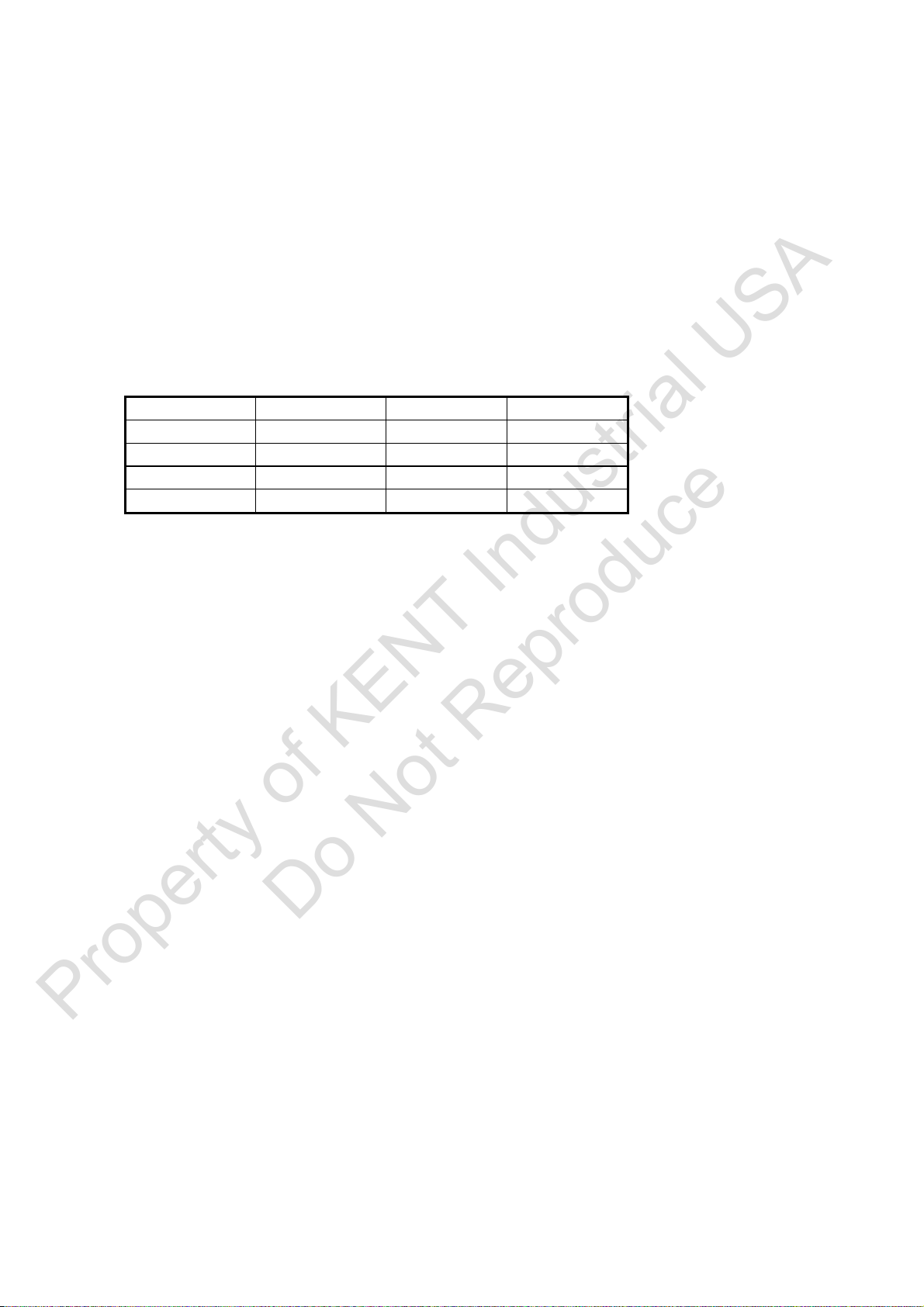
Models A B C
TRD-1230 1710mm 715mm 2780mm
TRD-1230H 1710mm 715mm 2780mm
TRD-1600H 2450mm 1020mm 3170mm
TRD-2000H 2908mm 1102mm 3470mm
Property of KENT Industrial USA
Do Not Reproduce

2-2
2.3
2.3.1
The machine
Description
Radial drills are purposely designed to process bulky objects. Kent USA has 20 years of
history and experience in behind. It knows radial drills certainly very well. Kent USA
radial drills will be your best choice. The material that the machine can process
on are : mild steel, metal, stainless steel, cast iron, aluminum, copper,,,, etc, except
magnesium alloy. (Note 1)
Note 1: Processing magnesium alloy may cause fire.
2.3.2 Parts
There are six categories of parts on the radial drill: Gearbox, Arm, Column, Top
Cover, Box Table and Base. The following are its description and locations.
1. Base The main aim of the base is to support the whole weight of the
machine. In addition, the cutting fluid is contained here and the
Box Table is installed on.
2. Gear box It is the core part for the radial drill for all procession is finished
here, like speed switch, auto feed, spindle,,, etc. They are inside
of the gearbox.
3. Arm It is to support the gearbox and is connected with the column.
4. Column It is to support the gearbox and the arm. It connects the base.
5. Top Cover It is at the top end of the Column.
6. Box table Working with clamps, it enables to reach the required accuracy.
7. The ball screw transmit
ion motor and clamping
mechanism.
The motor is to elevate the gearbox. The clamping
mechanism is to clamp both the Arm and the Column.
Property of KENT Industrial USA
Do Not Reproduce
2-3
2.4 Specifications.
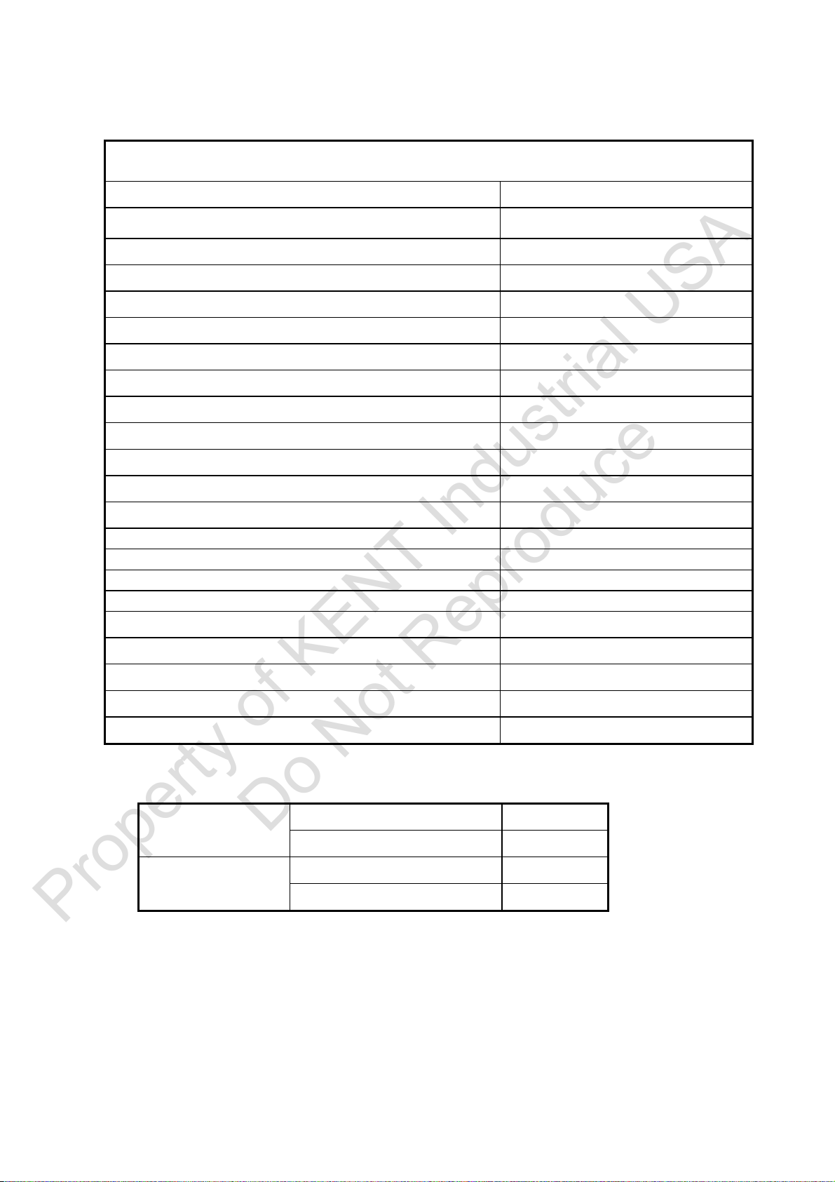
2.4.1 TRD-1230H Specification.
TRD-1230H
Diameter of column 300mm
Distance from Column surface to Spindle center, max. 1170mm
Distance from Column surface to Spindle center, min. 340mm
Travel of Spindle head 890mm
Distance from Base surface to Spindle end, max. 1370mm
Distance from Base surface to Spindle end, min. 490mm
Elevating height of Arm. 630mm
Effective area of Table. 635mm╳520mm╳415mm
The dimensions of the Base (L ╳W ╳ H) 1710mm╳715mm╳180mm
Taper hole Spindle. MT#4
Stroke of the Spindle. 250mm
R.P.M. of Spindle.(R.P.M.╳ step) 44-1500 12 steps
Feed of Spindle(REV.╳ step) 0.05,0.09,0.153 steps
Main motor. 2.25KW(3HP)
Elevating motor. 0.75KW(1HP)
Clamping motor. 0.75KW(1HP)
Coolant pump . 0.1KW(1/8HP)
Machine height from floor, max. 2780mm
Height from the Column top to floor 2060mm
Net weight (approx.)kgs 2100kg
Shipping Gross weight. (approx.)kgs 2300kg
Shipping dimensions(L╳W╳H) 2035mm╳995mm╳2240mm
The max. processing capacity.
Steel ∅42
Drilling
Cast iron ∅55
Steel ∅25
Taping
Cast Iron ∅38
Property of KENT Industrial USA
Do Not Reproduce
2-4
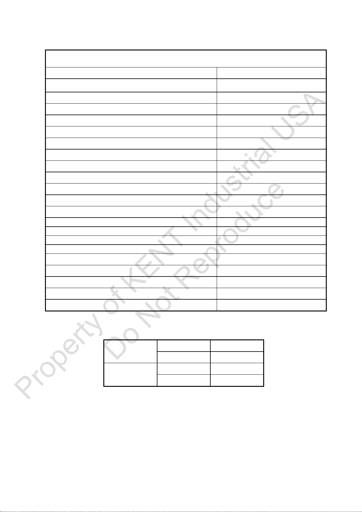
2.4.2 TRD-1230 Specification.
TRD-1230
Diameter of column 300mm
Distance from Column surface to Spindle center, max. 1170mm
Distance from Column surface to Spindle center, min. 340mm
Travel of Spindle head 890mm
Distance from Base surface to Spindle end, max. 1370mm
Distance from Base surface to Spindle end, min. 490mm
Elevating height of Arm. 630mm
Effective area of Table. 635mm╳520mm╳415mm
The dimensions of the Base (L ╳ W ╳ H) 1710mm╳715mm╳180mm
Taper hole Spindle. MT#4
Stroke of the Spindle. 250mm
R.P.M. of Spindle.(R.P.M.╳ step) 44-1500 12 steps
Feed of Spindle(REV.╳ step) 0.05,0.09,0.15 3 speeds
Main motor. 2.25KW(3HP)
Elevating motor. 0.75KW(1HP)
Clamping motor. 0.75KW(1HP)
Coolant pump . 0.1KW(1/8HP)
Machine height from floor, max. 2780mm
Height from the Column top to floor 2060mm
Net weight (approx.) kgs 2100kg
Shipping Gross weight. (approx.) kgs 2300kg
Shipping dimensions(L╳W╳H) 2035mm╳995mm╳2240mm
The max. processing capacity.
Steel ∅42
Drilling
Cast iron ∅55
Steel ∅25
Taping
Cast Iron ∅38
Property of KENT Industrial USA
Do Not Reproduce
2-5
2.4.3 TRD-1600H Specification.
TRD-1600H
Diameter of column 432mm
Distance from Column surface to Spindle center, max. 1580mm
Distance from Column surface to Spindle center, min. 440mm
Travel of Spindle head 1140mm
Distance from Base surface to Spindle end, max. 1600mm
Distance from Base surface to Spindle end, min. 380mm
Elevating height of Arm. 850mm
Effective area of Table. 700mm╳500mm╳400mm
The dimensions of the Base (L ╳ W ╳ H) 2450mm╳1020mm╳200mm
Taper hole Spindle. MT#5
Stroke of the Spindle. 370mm
R.P.M. of Spindle.(R.P.M.╳ step) 35 – 1890 12 steps
Feed of Spindle(REV.╳ step) 0.07 - 0.96 6 steps
Main motor. 5.625KW(7.5HP)
Elevating motor. 1.5KW(2HP)
Clamping motor. 0.75KW(1HP)
Coolant pump . 0.1KW(1/8HP)
Machine height from floor, max. 3170mm
Height from the Column top to floor 2660mm
Net weight (approx.) kgs 4600kg
Shipping Gross weight. (approx.) kgs 4900kg
Shipping dimensions(L╳W╳H) 2820mm╳1450mm╳2920mm
The max. processing capacity.
Steel ∅65
Drilling Cast iron ∅70
Steel ∅50
Taping Cast Iron ∅60
Property of KENT Industrial USA
Do Not Reproduce

2-6
2.4.4 TRD-2000H Specification.
TRD-2000H
Diameter of column 432mm
Distance from Column surface to Spindle center, max. 2000mm
Distance from Column surface to Spindle center, min. 490mm
Travel of Spindle head 1510mm
Distance from Base surface to Spindle end, max. 1900mm
Distance from Base surface to Spindle end, min. 500mm
Elevating height of Arm. 1100mm
Effective area of Table. 1000mm╳800mm╳500mm
The dimensions of the Base (L ╳ W ╳ H) 2908mm╳1102mm╳250mm
Taper hole Spindle. MT#5
Stroke of the Spindle. 370mm
R.P.M. of Spindle.(R.P.M.╳ step) 35 – 1890 12 steps
Feed of Spindle(REV.╳ step) 0.07 - 0.96 6 steps
Main motor. 5.625KW(7.5HP)
Elevating motor. 2.25KW(3HP)
Clamping motor. 0.75KW(1HP)
Coolant pump . 0.1KW(1/8HP)
Machine height from floor, max. 3470mm
Height from the Column top to floor 2960mm
Net weight (approx.) kgs 6100kg
Shipping Gross weight. (approx.) kgs 6600kg
Shipping dimensions(L╳W╳H) 3105mm╳1400mm╳3240mm
The max. processing capacity.
Steel ∅65
Drilling Cast iron ∅70
Steel ∅50
Taping Cast Iron ∅60
Property of KENT Industrial USA
Do Not Reproduce

2-7
2.5 Standard and Option Accessories.
(1) Standard Accessories:
a. Adjusting tools(including tool box)
b. Cooling equipment(including pump)
c. Lighting installation(including fluorescent lamp)
d. Box table
(2) Option Accessories:
a. Tilt worktable
2.6 Operation position and noise level.
2.6.1 Operation position: about 1 meter far from the gearbox surface.
Height: 1.6 meter from the ground.
2.6.2 The noise level.
(1)Before being processed,
When the turning speed is 1500 rpm, the noise level is 70 dB(A).
When the turning speed is 88 rpm, the noise level is 71 dB(A).
(Note :When using drill machine please wear the earmuffs.)
(2)When processing with tools,
The test conditions are as follow:
Material:SS41
Thickness:32mm
The tool diameter:∅32mm
When the turning speed is 88rpm and the feed rate is 0.09 mm, the noise level is 82 dB(A).
When the turning speed is 88rpm and the feed rate is 0.05 mm, the noise level is 80 dB(A)。
(Note : When using drill machine please wear the earmuffs.)
Property of KENT Industrial USA
Do Not Reproduce

3-1
CHAPTER 3
Preparation to Install
3.1 Space and room requirement
3.1.1 Floor requirement
Using this machine requires solid and well-structured floor and its good level.
Note:
1. For adjusting level, please refer to the chapter 6.
2. Adjusting level is needed before usin
g
this machine. The level ad
j
ustin
g
tolerance
must be within 1 mm/m.
TRD-1230H & TRD 1230 floor diagrams. (Unit : mm)
The above diagrams are for the bases and ground bolts, as well as its relative positions
of TRD-1230H & TRD 1230.
TRD-1600H floor diagrams. (Unit : mm)
The above diagrams are for the bases and ground bolts, as well as its relative positions
of TRD-1600H.
Property of KENT Industrial USA
Do Not Reproduce
This manual suits for next models
3
Table of contents


