KENT 908 7113 020 User manual

Razor E17
INSTRUCTION FOR USE
KENT model: 908 7113 020 ENGLISH
INSTRUCTIONS D’UTILISATION
Modèle KENT: 908 7113 020 FRANÇAIS
INSTRUCCIONES DE USO
Modelo KENT: 908 7113 020 ESPAÑOL
INSTRUÇÕES DE USO
Modelo KENT: 908 7113 020 PORTUGUÊS
Sim
p
le. Clean.
909 6311 000(3)2009-11
https://harrissupplyind.com-ToOrderPartsCall608-268-8080

https://harrissupplyind.com-ToOrderPartsCall608-268-8080

INSTRUCTIONS FOR USE ENGLISH
Razor E17 909 6311 000(3)2009-11 1
TABLE OF CONTENTS
INTRODUCTION.............................................................................................................................................................. 2
MANUAL PURPOSE AND CONTENTS .......................................................................................................................................... 2
TARGET........................................................................................................................................................................................... 2
HOW TO KEEP THIS MANUAL....................................................................................................................................................... 2
IDENTIFICATION DATA................................................................................................................................................................... 2
OTHER REFERENCE MANUALS................................................................................................................................................... 2
SPARE PARTS AND MAINTENANCE............................................................................................................................................. 2
CHANGES AND IMPROVEMENTS ................................................................................................................................................ 2
OPERATION CAPABILITIES........................................................................................................................................................... 2
CONVENTIONS .............................................................................................................................................................................. 2
UNPACKING/DELIVERY ................................................................................................................................................. 3
SAFETY ........................................................................................................................................................................... 3
SYMBOLS ....................................................................................................................................................................................... 3
GENERAL INSTRUCTIONS............................................................................................................................................................ 3
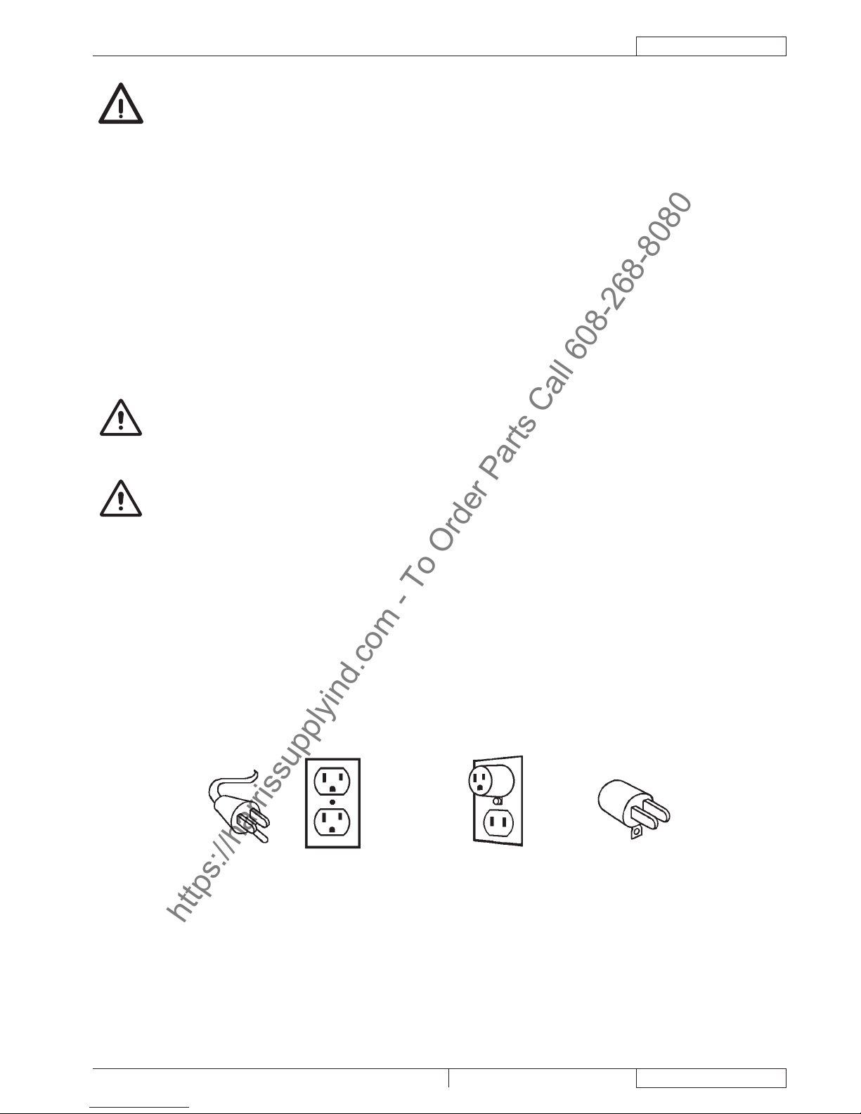
120 VAC GROUNDING INSTRUCTIONS ....................................................................................................................................... 5
MACHINE DESCRIPTION ............................................................................................................................................... 6
MACHINE STRUCTURE ................................................................................................................................................................. 6
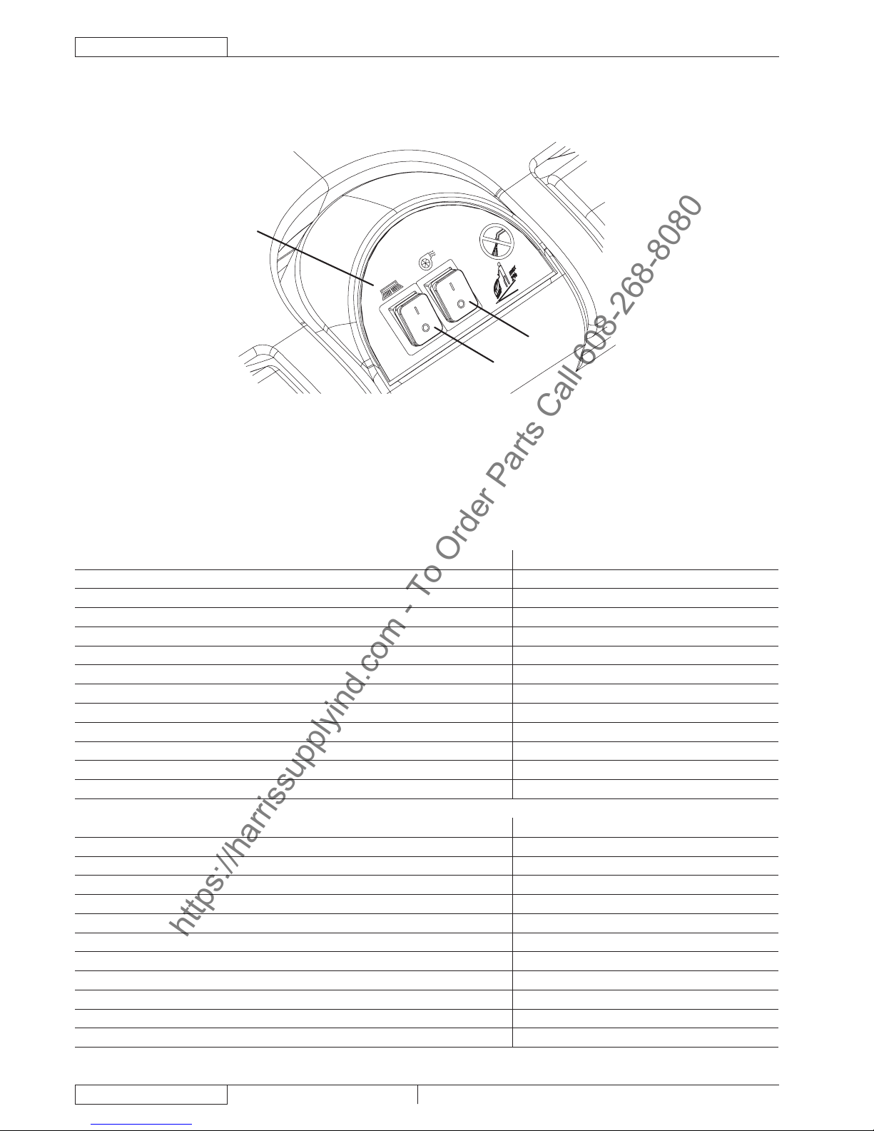
CONTROL PANEL........................................................................................................................................................................... 8
ACCESSORIES/OPTIONS.............................................................................................................................................................. 8
TECHNICAL DATA........................................................................................................................................................................... 9
WIRING DIAGRAM.......................................................................................................................................................................... 9
GROUNDING CONNECTION ......................................................................................................................................................... 9
USE ................................................................................................................................................................................ 10
BEFORE MACHINE START-UP.................................................................................................................................................... 10
MACHINE START AND STOP........................................................................................................................................................11
MACHINE OPERATION (SCRUBBING/DRYING)..........................................................................................................................11
MACHINE TRANSPORT/PARKING .............................................................................................................................................. 12
TANK EMPTYING.......................................................................................................................................................................... 12
AFTER USING THE MACHINE..................................................................................................................................................... 13
RECOVERY TANK REMOVAL ...................................................................................................................................................... 13
MACHINE LONG INACTIVITY ...................................................................................................................................................... 13
FIRST PERIOD OF USE ............................................................................................................................................................... 13
MAINTENANCE............................................................................................................................................................. 14
SCHEDULED MAINTENANCE TABLE ......................................................................................................................................... 14
INTEGRITY CHECK OF POWER SUPPLY CABLE AND EXTENSION........................................................................................ 14
SQUEEGEE CLEANING ............................................................................................................................................................... 15
SQUEEGEE BLADE CHECK AND REPLACEMENT.................................................................................................................... 15
BRUSH CLEANING....................................................................................................................................................................... 16
TANK AND VACUUM GRID CLEANING ....................................................................................................................................... 16
SOLUTION FILTER CLEANING.................................................................................................................................................... 17
MACHINE SPEED ADJUSTMENT ................................................................................................................................................ 17
TROUBLESHOOTING................................................................................................................................................... 18
SCRAPPING .................................................................................................................................................................. 18
https://harrissupplyind.com-ToOrderPartsCall608-268-8080

ENGLISH INSTRUCTIONS FOR USE
2909 6311 000(3)2009-11 Razor E17
INTRODUCTION
NOTE
The numbers in brackets refer to the components shown in Machine Description chapter.
MANUAL PURPOSE AND CONTENTS
The purpose of this Manual is to provide the operator with all necessary information to use the machine properly, in a safe and
autonomous way. It contains information about technical data, safety, operation, storage, maintenance, spare parts and disposal.
KENT in case of doubts concerning the interpretation of the instructions and for any further information.
TARGET
from the non-observance of this prohibition.
HOW TO KEEP THIS MANUAL
The User Manual must be kept near the machine, inside an adequate case, away from liquids and other substances that can cause
damage to it.
IDENTIFICATION DATA
The machine model and serial number are marked on the plate (1).
MACHINE model ...............................................................................
MACHINE serial number ...................................................................
OTHER REFERENCE MANUALS
Spare Parts List (supplied with the machine)–
Service Manual (that can be consulted at KENT Service Centers)–
SPARE PARTS AND MAINTENANCE
Only original spare parts and accessories must be used.
Contact KENT for service or to order spare parts and accessories, specifying the machine model and serial number.
CHANGES AND IMPROVEMENTS
KENT constantly improves its products and reserves the right to make changes and improvements at its discretion without being
Any change and/or addition of accessories must be approved and performed by KENT.
OPERATION CAPABILITIES
CONVENTIONS
Forward, backward, front, rear, left or right are intended with reference to the operator’s position, that is to say in driving position
with the hands on the handlebar (2).
https://harrissupplyind.com-ToOrderPartsCall608-268-8080

INSTRUCTIONS FOR USE ENGLISH
Razor E17 909 6311 000(3)2009-11 3
UNPACKING/DELIVERY
To unpack the machine, carefully follow the instructions on the packing.
When the machine is delivered, check that the packing and the machine were not damaged during transportation. In case of visible
Please check that the following items have been supplied with the machine:
Scrubber-dryer User Manual–
Scrubber-dryer Spare Parts List–
Supply cable extension–
SAFETY
The following symbols indicate potentially dangerous situations. Always read this information carefully and take all necessary
precautions to safeguard people and property.
The operator’s cooperation is essential in order to prevent injury. No accident prevention program is effective without the total
cooperation of the person responsible for the machine operation. Most of the accidents that may occur in a factory, while working
or moving around, are caused by failure to comply with the simplest rules for exercising prudence. A careful and prudent operator is
the best guarantee against accidents and is essential for successful completion of any prevention program.
SYMBOLS
DANGER!
It indicates a dangerous situation with risk of death for the operator.
WARNING!
It indicates a potential risk of injury for people.
CAUTION!
It indicates a caution or a remark related to important or useful functions.
Pay careful attention to the paragraphs marked by this symbol.
NOTE
It indicates a remark related to important or useful functions.
CONSULTATION
It indicates the necessity to refer to the Quick Start Guide before performing any procedure.
GENERAL INSTRUCTIONS
DANGER!
Before performing any maintenance, repair, cleaning or replacement procedure disconnect the plug from the–
electrical mains.
This machine must be used by properly trained operators only. Children or disabled people cannot use this–
machine.
Do not wear jewels when working near electrical components.–
Do not work under the lifted machine without supporting it with safety stands.–
–
This machine is not suitable for collecting dangerous powders.
https://harrissupplyind.com-ToOrderPartsCall608-268-8080

ENGLISH INSTRUCTIONS FOR USE
4909 6311 000(3)2009-11 Razor E17
WARNING!
–
malfunction or breakdown, grounding connection reduces the risk of electric shock.
The power supply cable plug must be connected to an appropriate outlet, which is grounded according to–
law in force.
–
properly grounded.
Do not tamper with the power supply cable plug. If the power supply cable plug cannot be connected to the–
–
Do not unplug the machine by pulling the supply cable. To unplug, grasp the plug, not the cable.–
Do not handle the plug or the machine with wet hands.–
Turn off all controls before unplugging.–
Regularly check the power supply cable for damages, cracks, cuts and wear. If necessary, replace it.–
–
Centre.
–
technician.
–
handle. Do not close a door on the power supply cable, or pull the power supply cable around sharp edges
or corners. Do not run the machine on the power supply cable.
The brushes must not come into contact with the power supply cable.–
–
–
in. Disconnect the machine from the electrical mains when not in use and before performing maintenance
procedures.
–
–
not be used or kept outdoors in wet conditions.
–
Do not allow to be used as a toy. Close attention is necessary when used near children.–
–
–
Do not use the machine on incline.–
Do not use the machine in particularly dusty areas.–
While using this machine, take care not to cause damage to people or objects.–
–
–
The machine working temperature must be between +32°F and +104°F (0°C and +40°C).–
The machine storage temperature must be between +32°F and +104°F (0°C and +40°C).–
The humidity must be between 30% and 95%.–
–
–
Do not use the machine as a means of transport.–
–
–
Do not tamper with the machine safety guards and follow the ordinary maintenance instructions–
scrupulously.
Do not allow any object to enter into the openings. Do not use the machine if the openings are clogged.–
Always keep the openings free from dust, hairs and any other foreign material which could reduce the air
–
This machine cannot be used on roads or public streets.–
Pay attention during machine transportation when temperature is below freezing point. The water in the–
–
brushes or pads could reduce safety.
–
https://harrissupplyind.com-ToOrderPartsCall608-268-8080

INSTRUCTIONS FOR USE ENGLISH
Razor E17 909 6311 000(3)2009-11 5
WARNING!
If the machine–
does not work properly
is damaged
has water or foam leaks
has been left outdoors exposed to bad weather conditions
is wet or has been dropped into water
–
–
–
–
The machine must be disposed of properly, because of the presence of toxic-harmful materials (electronic–
chapter).
120 VAC GROUNDING INSTRUCTIONS
This appliance must be grounded. If it should electrically malfunction, grounding provides a path of least resistance for electric
current to reduce the risk of electric shock. This appliance is equipped with a cord having an equipment-grounding conductor and
grounding plug. The plug must be plugged into an appropriate outlet that is properly installed and grounded in accordance with all
local codes and ordinances.
WARNING!
minimum length 15 feet–
type S, or ST, or SO, or STO, or STW–
–
DANGER!
–
This appliance is for use on a nominal 120 V circuit, and has a grounding plug that looks like the plug (B, Fig.–
1). A temporary adapter (B and C) may be used to connect this plug to a 2-pole receptacle (B), if a properly
in Canada.
Replace the plug if the grounding pin is damaged or broken.–
–
attached to the grounding pin only.
–
A B C
Figure 1
S310183A
https://harrissupplyind.com-ToOrderPartsCall608-268-8080

ENGLISH INSTRUCTIONS FOR USE
6909 6311 000(3)2009-11 Razor E17
26
25
619 2
17
16
3
21
27
24
23
10 9
820
1
5a
5b
18
47
13
14 15
11
15
12
22
23a 23b
13 14
S311245K
MACHINE DESCRIPTION
MACHINE STRUCTURE
Serial number plate/technical data1.
Handlebar2.
Handlebar inclination adjusting knob3.
4.
5a.
5b.
Recovery tank cover6.
Rear support wheel for transport/parking7.
8.
Brush/pad9.
Brush/pad-holder deck10.
Squeegee11.
Squeegee mounting handwheels12.
Front squeegee blade13.
Rear squeegee blade14.
Squeegee blade mounting springs15.
Recovery water drain hose16.
Recovery water drain hose bracket17.
Solution drain valve18.
Squeegee lifting/lowering lever19.
20.
Power supply cable21.
Squeegee vacuum hose22.
Transport/parking device23.
Transport/parking device (engaged)23a.
Transport/parking device (disengaged)23b.
Transport/parking device positioning pin24.
Brush/pad-holder support25.
Recovery tank26.
Solution tank27.
https://harrissupplyind.com-ToOrderPartsCall608-268-8080

INSTRUCTIONS FOR USE ENGLISH
Razor E17 909 6311 000(3)2009-11 7
49
38
39
46
41
45
40
37
36
34
31
32
48
47
35
33
42 43
44
S311248K
MACHINE STRUCTURE (Continues)
Recovery tank cover (open)31.
Recovery tank cover gasket32.
Brush/pad-holder support33.
Recovery tank compartment34.
35.
36.
Recovery water drain hole37.
Vacuum system motor38.
Brush/pad-holder motor39.
Brush/pad-holder deck40.
Machine speed adjusting screw41.
Brush42.
Pad-holder43.
Pad44.
Terminal board box45.
Screw46.
Compensation hole47.
Cover support rod (engaged)48.
Brush/pad-holder engagement rotation direction49.
https://harrissupplyind.com-ToOrderPartsCall608-268-8080

ENGLISH INSTRUCTIONS FOR USE
8909 6311 000(3)2009-11 Razor E17
CONTROL PANEL
Control panel51.
Brush/pad-holder switch52.
Vacuum system switch53.
51
52
53
S310237A
ACCESSORIES/OPTIONS
In addition to the standard components, the machine can be equipped with the following accessories/options, according to the
Brushes/pads of different materials–
Curved squeegee–
For further information concerning the optional accessories, contact an authorised Retailer.
TECHNICAL DATA
General Values
Machine length 44 in (1,120 mm)
Machine width with squeegee 28.3 in (720 mm)
Machine width without squeegee 22.4 in (570 mm)
Min/max machine height with adjustable handlebar 33.8 - 43.5 in (860 - 1,105 mm)
Total machine weight 165,3 lb (75 kg)
Minimum turning radius 29.5 in (750 mm)
Cleaning width 17 in (430 mm)
Central wheel diameter 9.8 in (250 mm)
Brush/pad diameter 16.9 - 17 in (430 - 432 mm)
145 psi (1.0 N/mm2)
275.5 psi (1.9 N/mm2)
61,7 lb (28 kg)
Performance Values
Vacuuming 51.8 inH2O (1,316 mmH2O)
Brush/pad-holder motor speed 170 rpm
Sound pressure level at workstation (ISO 11201, ISO 4871) (LpA) 70 dB(A) ± 3dB(A)
Machine sound pressure level (ISO 3744, ISO 4871) (LwA) 87 dB(A)
Vibration level at the operator’s arms (ISO 5349-1) (< 2.5 m/s2)
Vacuum system motor power 0.73 hp (550 W)
Brush/pad motor power 0.73 hp (550 W)
Gradeability 2%
System voltage 115 V - 60 Hz
Clean water tank capacity 8.2 gal (31 litres)
Recovery tank capacity 7.7 gal (29 litres)
https://harrissupplyind.com-ToOrderPartsCall608-268-8080

INSTRUCTIONS FOR USE ENGLISH
Razor E17 909 6311 000(3)2009-11 9
WIRING DIAGRAM
Key
C1 Suppressor
EV1 Water solenoid valve
FR Frame
M1 Brush/pad-holder motor
M2 Vacuum system motor
PL Plug
SW1 Brush/pad-holder switch
SW2 Vacuum system switch
Colour codes
BK Black
BU Blue
BN Brown
GN Green
GY Grey
OG Orange
PK Pink
RD Red
VT Violet
WH White
YE Yellow
S310239A
GROUNDING CONNECTION
(see Fig. 2)
Grounding pinA.
Grounded outletB.
Grounded outlet boxC.
AdapterD.
Metal screwE.
AdapterF.
Grounding screw tabG.
A
B
C
D
E
F
G
Figure 2
S310183B
https://harrissupplyind.com-ToOrderPartsCall608-268-8080

ENGLISH INSTRUCTIONS FOR USE
10 909 6311 000(3)2009-11 Razor E17
USE
WARNING!
–
–
–
–
While reading this Manual, the operator must pay particular attention to the symbols shown on the plates.
Do not cover these plates for any reason and immediately replace them if damaged.
BEFORE MACHINE START-UP
Brush or pad-holder installation
NOTE
Insert the positioning pin (24) and disengage the machine transport/parking device (23b).1.
Lift the brush/pad-holder deck (10) by prying the handlebar (2).2.
Place the brush (42) or the pad-holder (43) under the deck.3.
Lower the deck (10) by using the handlebar (2).4.
Connect the power supply cable (21) to the electrical mains.5.
Engage the brush/pad-holder by pressing the brush/pad switch (52) for a few seconds.6.
Brush/pad application guide (suggestions only)
Types of brushes available Midlite Grit 180 Midgrit 240 Prolite Union Mix
General cleaning
Concrete
Ceramic tiles/quarrystones
Marble
Vinyl tiles
Rubber tiles
Polishing
Rubber tiles
Marble
Vinyl tiles
Squeegee installation
Install the squeegee (11) and fasten it with the handwheels (12), then connect the vacuum hose (22) to the squeegee.7.
Open the recovery water tank cover (41) and engage the support rod (59).8.
9.
Always follow the dilution instructions on the label of the chemical product used to prepare the solution.
The solution temperature must not exceed 104°F (40°C).
CAUTION!
Adjustments
Adjust the handlebar (2) with the knobs (3) to reach a comfortable position.10.
https://harrissupplyind.com-ToOrderPartsCall608-268-8080

INSTRUCTIONS FOR USE ENGLISH
Razor E17 909 6311 000(3)2009-11 11
MACHINE START AND STOP
Starting the machine
Prepare the machine as shown in the previous paragraph.1.
Drive the machine to the working place by pushing it with the hands on the handlebar (2).2.
Connect the power supply cable (21) to the electrical mains.3.
WARNING!
Lower the squeegee (11) with the lever (19).4.
5.
While keeping the hand on the handlebar (2), start the machine by turning the brush/pad-holder switch and the vacuum system6.
switch (52 and 53) to “I”.
Stopping the machine
Turn the brush/pad-holder switch and the vacuum system switch (52 and 53) to “0”.7.
Disconnect the power supply cable (21) from the electrical mains.8.
Lift the squeegee with the lever (19).9.
Insert the positioning pin (24) and lift the brush/pad-holder by engaging the transport/parking device (23a).10.
MACHINE OPERATION (SCRUBBING/DRYING)
Start the machine as shown in the previous paragraph.1.
2.
CAUTION!
CAUTION!
If necessary, adjust the solution quantity by using the lever (4).3.
NOTE
A
B
Figure 3
P100160B
Machine speed adjustment
4.
If necessary, it is possible to adjust the machine speed, according to the procedure shown in Maintenance chapter.
https://harrissupplyind.com-ToOrderPartsCall608-268-8080

ENGLISH INSTRUCTIONS FOR USE
12 909 6311 000(3)2009-11 Razor E17
MACHINE TRANSPORT/PARKING
To transport/park the machine, proceed as follows.
Turn the brush/pad-holder switch and the vacuum system switch (52 and 53) to “0”.1.
Disconnect the power supply cable (21) from the electrical mains and place it on the holder.2.
Lift the squeegee with the lever (19).3.
4.
machine in this position, drive it to the transport/parking area.
5.
the deck by using the release device (see the procedure in After Using The Machine paragraph), then place it on the support
(25).
Figure 4
S310234
TANK EMPTYING
CAUTION!
When the recovery tank (26) is full, empty it according to the following procedure.
Recovery tank emptying
Start the machine by pressing the brush/pad-holder and vacuum system switches (52 and 53).1.
Disconnect the power supply cable (21) from the electrical mains and place it on the holder.2.
Lift the squeegee with the lever (19).3.
Drive the machine to the appointed disposal area.4.
Insert the positioning pin (24) and lift the brush/pad-holder by engaging the transport/parking device (23a).5.
Empty the recovery tank (26) with the drain hose (16).6.
Then, rinse the tank with clean water.
Solution tank emptying
Perform steps 1 to 4.
Empty the solution tank (27) by using the drain valve (18).7.
Then, rinse the tank with clean water.8.
https://harrissupplyind.com-ToOrderPartsCall608-268-8080

INSTRUCTIONS FOR USE ENGLISH
Razor E17 909 6311 000(3)2009-11 13
AFTER USING THE MACHINE
After working, before leaving the machine:
Remove the brush/pad-holder as follows:1.
With the brush/pad-holder lifted, turn the brush/pad-holder switch (52) to “I” and, after a few seconds, back to “0”, thus
releasing the brush/pad-holder.
Disconnect the power supply cable (21) from the electrical mains and place it on the holder.2.
Empty the tanks (26 and 27) as shown in the previous paragraph.3.
Perform the daily maintenance procedures (see the Maintenance chapter).4.
Store the machine in a clean and dry place, with the brush/pad-holder and the squeegee lifted or removed.5.
RECOVERY TANK REMOVAL
To perform check and maintenance procedures, it may be necessary to remove the recovery tank (26) as shown below.
Empty the recovery tank (26) as shown in the relevant paragraph.1.
2.
Make sure that the power supply cable (21) is disconnected from the electrical mains.3.
Disconnect the vacuum hose (22) from the squeegee (11).4.
Disconnect the recovery water drain hose (16) from the bracket (17).5.
Open the cover (6).6.
Grasp the recovery tank (A, Fig. 5) in the area (B) and slightly raise it.7.
Disconnect the vacuum hose (C) from the tank, then remove the tank (A) with the hoses (D) and (E).8.
A
C
B
D
E
Figure 5
S310243A
MACHINE LONG INACTIVITY
If the machine is not going to be used for more than 30 days, proceed as follows:
Perform the procedures shown in After Using the Machine paragraph.1.
Store the machine in a clean and dry place.2.
FIRST PERIOD OF USE
and leakage.
https://harrissupplyind.com-ToOrderPartsCall608-268-8080

ENGLISH INSTRUCTIONS FOR USE
14 909 6311 000(3)2009-11 Razor E17
MAINTENANCE
The lifespan of the machine and its maximum operating safety are ensured by correct and regular maintenance.
The following chart provides the scheduled maintenance. The intervals shown may vary according to particular working conditions,
WARNING!
Maintenance procedures must be performed with the machine switched off and the power supply cable
disconnected from the electrical mains.
Center.
This Manual describes only the easier and most common maintenance procedures.
NOTE
SCHEDULED MAINTENANCE TABLE
Procedure Daily, after using
the machine Weekly Every six
months Yearly
Squeegee cleaning
Brush cleaning
Tank and vacuum grid cleaning
Squeegee blade check and replacement
Screw and nut tightening check (1)
Vacuum system motor carbon brush check and replacement (2)
(1)
This maintenance procedure must be performed by KENT authorised Service Center.(2)
INTEGRITY CHECK OF POWER SUPPLY CABLE AND EXTENSION
Carefully check if the power supply cable, the extension and the plugs are worn or damaged.
If necessary, have them replaced by the Service Center.
https://harrissupplyind.com-ToOrderPartsCall608-268-8080

INSTRUCTIONS FOR USE ENGLISH
Razor E17 909 6311 000(3)2009-11 15
SQUEEGEE CLEANING
NOTE
The squeegee must be clean and its blades must be in good conditions in order to get a good drying.
CAUTION!
1.
Make sure that the power supply cable (21) is disconnected from the electrical mains.2.
Lower the squeegee with the lever (19).3.
Disconnect the vacuum hose (22) from the squeegee.4.
Loosen the handwheels (12) and remove the squeegee (11).5.
Wash and clean the squeegee. In particular, clean the compartments (A, Fig. 6) and the vacuum hole (B) from dirt and debris.6.
Check the front blade (C) and the rear blade (D) for integrity, cuts and tears; if necessary replace them (see the procedure in7.
the following paragraph).
Assemble the components in the reverse order of disassembly.8.
SQUEEGEE BLADE CHECK AND REPLACEMENT
Clean the squeegee as shown in the previous paragraph.1.
Check that the front blade edges (E, Fig. 6) and the rear blade edges (I) lay down on the same level, along their length; if2.
necessary adjust the height according to the following procedure:
Remove the mounting springs (F), then adjust the front blade (C) and the rear blade (D).
Install the mounting springs on the front and rear blades.
Check the front blade (C) and rear blade (D) for integrity, cuts and tears; if necessary replace them as shown below. Also3.
check the front corner (H) of the rear blade for wear; if it is worn, overturn the blade to replace the worn corner with the other
one (I), if it is integral. If the other corner is worn too, replace the blade according to the following procedure:
Remove the mounting springs (F) and then replace (or overturn) the rear blade (D).
Install the mounting springs on the front and rear blades.
Install the squeegee (11) and screw tighten the handwheels (12).4.
Connect the vacuum hose (22) to the squeegee (11).5.
5 9 12 7
1
2
1
6
6
4
3
Figure 6
S310240
https://harrissupplyind.com-ToOrderPartsCall608-268-8080

ENGLISH INSTRUCTIONS FOR USE
16 909 6311 000(3)2009-11 Razor E17
BRUSH CLEANING
NOTE
Remove the brush, as shown in Use chapter.1.
Clean the brush with water and detergent.2.
Check the brush bristles for integrity and wear; if necessary, replace the brush.3.
TANK AND VACUUM GRID CLEANING
Drive the machine to the appointed disposal area.1.
Make sure that the power supply cable (21) is disconnected from the electrical mains.2.
Open the cover (6), then clean and wash the cover, the tanks (26 and 27) and the vacuum grid (36) with clean water.3.
Drain the water from the tanks with the drain hose (16) and the valve (18).
4.
reinstall them.
Check the recovery tank cover gasket (D) for integrity.5.
NOTE
If necessary replace the gasket (D) by removing it from its housing (E).
Check the seating surface (D) of the gasket (G) for integrity and sealing capabilities.6.
Check the compensation hole (47) for clogging.7.
NOTE
Close the recovery tank cover (6).8.
C
B
B
A
D
F
G
E
Figure 7
S311227A
https://harrissupplyind.com-ToOrderPartsCall608-268-8080

INSTRUCTIONS FOR USE ENGLISH
Razor E17 909 6311 000(3)2009-11 17
SOLUTION FILTER CLEANING
Empty the solution tank (27) as shown in the relevant paragraph.1.
2.
Make sure that the power supply cable (21) is disconnected from the electrical mains.3.
4.
NOTE
C
B
A
B
D
Figure 8
S310232A
MACHINE SPEED ADJUSTMENT
NOTE
Remove the recovery tank as shown in Use chapter.1.
Adjust the machine speed with the screw (41) as shown below:2.
Loosen the screw (46), on the right side of the machine, by turning it counter-clockwise.
Turn the adjusting screw (41) counter-clockwise to increase the machine speed.
Turn the adjusting screw (41) clockwise to decrease the machine speed.
After adjusting, tighten the screw (46).
Install the recovery tank as shown in Use chapter.3.
With the machine ready to operate, perform hands-on tests of the machine and, if other adjustments are necessary, repeat4.
steps 1 to 4.
https://harrissupplyind.com-ToOrderPartsCall608-268-8080

ENGLISH INSTRUCTIONS FOR USE
18 909 6311 000(3)2009-11 Razor E17
TROUBLESHOOTING
Trouble Possible Cause Remedy
The motors do not turn on The power supply cable (21) is faulty or
disconnected from the electrical mains Replace or connect the cable
The recovery water tank (26) is full Empty
is closing
The vacuum hose (22) is disconnected from
the squeegee (11) or it is damaged Connect
The squeegee (11) is dirty, or the squeegee
blades (13, 14) are worn or damaged Clean the squeegee or replace the blades
The recovery water tank cover (6) is not
properly closed, or the gasket (32) is
damaged
Check and/or clean the seating surface or
replace the gasket
The recovery water tank (6) is dirty (clogged
drain hole) Clean
Clean
There is debris under the squeegee blades
(13, 14). Remove the debris
The squeegee blades (13, 14) are worn,
chipped or torn Replace the blades
For further information refer to the Service Manual, available at any KENT Service Center.
SCRAPPING
Before scrapping the machine, remove and separate the following materials, which must be disposed of properly according to the
Law in force:
Brush–
Pad–
Electrical and electronic components (*)–
Refer to the nearest KENT Center especially when scrapping electrical and electronic components.(*)
https://harrissupplyind.com-ToOrderPartsCall608-268-8080
This manual suits for next models
2
Table of contents
Languages:
Other KENT Blower manuals
Popular Blower manuals by other brands

Maruyama
Maruyama BL3200 Owner's/operator's manual

Echo
Echo PB-403 Operator's manual

Echo
Echo PB-770 Operator's manual

Nilfisk-Advance
Nilfisk-Advance Terra 5200B Instructions for use

Echo
Echo PB-251E - PARTS CATALOG SN P07611001001 - P07611999999 REV... parts catalog

Cocraft
Cocraft LB24 Original instructions