KENT Blue 32 User manual

ToOrderPartsCall1-888-702-5326-https://monsterfloorequipmentparts.com
Blue 32
INSTRUCTIONS FOR USE
KENT model: 908 4106 010
MODE D’EMPLOI ET D’ENTRETIEN
Modèle KENT: 908 4106 010
INSTRUCCIONES DE USO
Modelo KENT: 908 4106 010
INSTRUÇÕES DE USO
Modelo KENT: 908 4106 010
146 2301 000(1)2005-03

ToOrderPartsCall1-888-702-5326-https://monsterfloorequipmentparts.com
Blue 32 – 146 2301 000(1)2005-03
9
8
7
96
1
9
54
3
9
2
B
S310025
C
S310080
D
S310027
E
S310028
F
S310029
G
S310030
H
S310081
I
S310032
J
S310082
K
S310034

ToOrderPartsCall1-888-702-5326-https://monsterfloorequipmentparts.com
INSTRUCTIONS FOR USE
Blue 32 – 146 2301 000(1)2005-03 1
INTRODUCTION....................................................................................................................... 2
PURPOSE AND CONTENTS OF THIS MANUAL.............................................................................................2
IDENTIFICATION DATA.................................................................................................................................... 2
OTHER REFERENCE MANUALS..................................................................................................................... 2
SPARE PARTS AND MAINTENANCE .............................................................................................................. 2
MODIFICATIONS AND IMPROVEMENTS........................................................................................................ 2
SAFETY - ACCIDENT PREVENTION ...................................................................................... 2
SYMBOLS.......................................................................................................................................................... 2
GENERAL SAFETY INSTRUCTIONS............................................................................................................... 3
UNPACKING............................................................................................................................. 3
MACHINE DESCRIPTION ........................................................................................................ 4
SWEEPER OPERATION CAPABILITIES.......................................................................................................... 4
TECHNICAL DATA ............................................................................................................................................ 4
ELECTRICAL PROTECTIONS.......................................................................................................................... 5
ACCESSORIES / OPTIONS.............................................................................................................................. 5
MACHINE USE ......................................................................................................................... 5
BATTERY CHECK/INSTALLATION ON A NEW MACHINE ............................................................................. 5
BATTERY INSTALLATION AND BATTERY TYPE SETTING (WET OR GEL)................................................. 6
BEFORE START-UP ......................................................................................................................................... 6
STARTING AND STOPPING THE MACHINE................................................................................................... 6
MACHINE OPERATION .................................................................................................................................... 7
EMPTYING THE HOPPER................................................................................................................................ 7
AFTER MACHINE USE ..................................................................................................................................... 7
PUSHING THE MACHINE................................................................................................................................. 7
MACHINE STORAGE........................................................................................................................................ 7
MAINTENANCE........................................................................................................................ 8
SCHEDULED MAINTENANCE TABLE ............................................................................................................. 8
MAIN BROOM HEIGHT CHECK ....................................................................................................................... 9
MAIN BROOM REPLACEMENT ....................................................................................................................... 9
SIDE BROOM HEIGHT ADJUSTMENT .......................................................................................................... 10
SIDE BROOM REPLACEMENT ...................................................................................................................... 10
DUST FILTER CLEANING AND INTEGRITY CHECK .................................................................................... 10
SKIRT HEIGHT AND OPERATION CHECK ................................................................................................... 11
BATTERY CHARGING .................................................................................................................................... 11
SAFETY FUNCTIONS AND TROUBLESHOOTING.............................................................. 12
HOOD SAFETY SWITCH ................................................................................................................................ 12
TROUBLESHOOTING............................................................................................................ 12
SCRAPPING ........................................................................................................................... 12

ToOrderPartsCall1-888-702-5326-https://monsterfloorequipmentparts.com
INSTRUCTIONS FOR USE
2Blue 32 – 146 2301 000(1)2005-03
INTRODUCTION
PURPOSE AND CONTENTS OF THIS
MANUAL
The purpose of this manual is to provide the Customer
with all necessary information to use the machine properly
in a safe way. It contains information about technical
characteristics, operation, machine storage, maintenance,
spare parts and safety conditions.
This manual is intended for Operators and Technicians
qualified for performing the machine maintenance.
Before carrying out any procedure on the machine, the
Operators and Qualified Technicians must read this
manual carefully. Contact the Manufacturer in case of
doubts regarding the interpretation of the instructions and
for any further information.
IDENTIFICATION DATA
The Machine Model and Serial Number are marked on the
nameplate that is located under the hood. (20, Fig. U).
The machine production year is shown after the Date
Code on the serial plate. (A04 means January 2004)
This information is useful when machine and engine
replacement parts are required. Use the following table to
write down the machine identification data for any future
reference.
OTHER REFERENCE MANUALS
– Electronic Battery Charger Manual, also provided, is
to be considered an integral part of this manual.
The following manuals are also available:
– Service Manual (that can be consulted at any Kent
Service Center)
– Parts List, supplied with the machine
SPARE PARTS AND MAINTENANCE
All extraordinary maintenance and repairs must be carried
out by qualified personnel or by Kent Service Centers.
Only original spare parts and accessories should be used.
Call Kent for service or to order spare parts and
accessories. Specify the machine Model and Serial
Number when discussing your machine.
MODIFICATIONS AND IMPROVEMENTS
Our Company constantly improves its products and
reserves the right to make changes and improvements at
its discretion without being obliged to apply such benefits
to the machines that were previously sold.
Any modifications and/or the addition of accessories must
be approved and performed by the Manufacturer.
SAFETY - ACCIDENT PREVENTION
The following symbols indicate potentially dangerous
situations. Always carefully read this information and take
the necessary precautions to protect people and property.
No accident prevention program is effective without the
total cooperation of the person responsible for the
machine operation. Most of the accidents that may occur
in a factory, while working or transporting the machine, are
caused by the failure to comply with the most simple
prudence rules. A careful and prudent user is the best
guarantee against accidents and is a prerequisite to carry
out any accident prevention program.
SYMBOLS
MACHINE Model..........................................................
MACHINE Serial Number.............................................
DANGER!
Is used to warn of immediate hazards that
will cause severe personal injury or death.
WARNING!
Is used to call attention to a situation that
could cause severe personal injury.
CAUTION!
Is used to call attention to a situation that
could cause minor personal injury or
damage to the machine or property.
CONSULTATION
Consult the instruction booklet before
performing any operation.

ToOrderPartsCall1-888-702-5326-https://monsterfloorequipmentparts.com
INSTRUCTIONS FOR USE
Blue 32 – 146 2301 000(1)2005-03 3
GENERAL SAFETY INSTRUCTIONS
Specific warnings and cautions to inform you about
potential exposure to bodily harm and machine damage
are listed below.
– To perform maintenance/repair procedures turn the
machine ignition key to the OFF position and
disconnect the battery.
– This machine must be used by qualified and
authorized personnel only. Children or disabled
people cannot use this machine.
– Keep the battery far from sparks, flames and smoke.
Explosive gases are vented during normal operation.
– Do not wear jewelry when working near electrical
components.
– Do not work under the lifted machine if it is not
securely supported.
– Do not operate the machine near dangerous,
flammable and/or explosive powders, liquids or
vapors.
– Battery charging produces explosive hydrogen gas.
Keep the hood open during battery charging and
perform the operation only in well-ventilated areas
and far from open flames.
– When wet (lead-acid) batteries are mounted on this
machine, do not tilt the machine more than 30° from
its horizontal position. Doing so could cause the
highly corrosive acid to leak out of the batteries.
When it is necessary to tilt the machine for
maintenance, remove the batteries.
– Carefully read all maintenance/repair instructions
before carrying out any maintenance/repair
procedure.
– Take all necessary precautions to prevent hair,
jewelry and loose clothing from being caught in
moving parts.
– Do not smoke during battery charging.
– Do not leave the machine unattended with the ignition
key inserted and the parking brake deactivated, if
equipped,.
– Do not use the machine on surfaces with a gradient
greater than 2%.
– Do not wash the machine with pressurized water, or
with corrosive substances. Do not use compressed
air to clean this type of machine.
– Do not use the machine in extremely dusty areas.
– During the use of this machine take care not to
endanger other people.
– Storage temperature must be within +32°F - +104°F
(0°C - +40°C).
– The machine working temperature must be within
+32°F - +104°F (0°C - +40°C).
– Humidity range should be within 30% and 95%.
– Do not use the machine as a transport vehicle.
– Do not allow the brooms to operate while the machine
is stationary to avoid damaging the floor.
– In case of fire, use a powder extinguisher. Do not use
water.
– Do not bump into shelves or scaffolding where there
is a risk of falling objects.
– Adjust the operating speed according to the floor
conditions.
– Do not tamper with the machine safety guards; follow
the ordinary maintenance instructions scrupulously.
– Do not remove or modify the plates affixed on the
machine.
– In case of machine malfunctions ensure that these
are not caused by a lack of maintenance. Otherwise,
request assistance from the authorized personnel or
a Service Center.
– If parts must be replaced, request ORIGINAL spare
parts from a dealer or Authorized Retailer.
– To ensure proper machine operation and safety
conditions, the authorized personnel or Service
Center must carry out the Scheduled Maintenance
detailed in the related chapter of this Manual.
– The machine must be disposed of properly, at the end
of its cycle of life, because of the presence of
toxic-harmful materials (battery acid, oil, etc.), which
are subject to standards that require disposal in
special centers (see chapter “Scrapping”).
– If the machine is used according to the instructions, it
will not produce dangerous levels of vibration. The
machine vibration level is below 2.5 m/s2.
UNPACKING
When the machine is delivered, check that the carton and
the machine were not damaged during shipping. If
damage is evident, keep the packing materials and have it
checked by the Parcel Service that delivered it. Call the
Parcel Service immediately to fill out a request for a
compensation for damages.
Please check that the following items have been supplied
with the machine:
1. Technical documents: Sweeper Instruction for Use
Electronic Battery Charger Manual, Parts List
2. Side broom fuse (1)
3. Spare battery cables, terminal boots
4. Electronics fuse (1)
DANGER!
WARNING!

ToOrderPartsCall1-888-702-5326-https://monsterfloorequipmentparts.com
INSTRUCTIONS FOR USE
4Blue 32 – 146 2301 000(1)2005-03
MACHINE DESCRIPTION
SWEEPER OPERATION CAPABILITIES
The Sweeper is designed and constructed to sweep
non-hazardous dust or light debris on smooth and solid
floors, light carpeting, in civil or industrial environments,
under safe operating conditions by a trained Operator.
Control panel
(See Fig. B)
1. Control panel
2. Ignition key
3. Discharged battery warning light
4. Semi-discharged battery warning light
5. Charged battery warning light
6. Display
7. Display selection button: hour counter/ hour and
minutes counter / battery voltage (V),
8. Filter shaker push-button (optional)
9. Panel fastening screws
Exterior general overview
(See Fig. C)
1. Serial number plate / technical data
2. Side broom latch
3. Handlebar
4. Drive lever
5. Knobs to adjust the handlebar inclination
6. Can holder
7. Hood
8. Rear wheels
9. Pivoting front wheel
10. Side broom
11. Main broom
12. Side broom lifting and adjusting knob
13. Left side skirt
14. Right side skirt
15. Front skirt
16. Rear skirt
17. Hopper
18. Hopper latch
19. Hopper handle
20. Manual filter-shaker handle
21. Main broom access door
22. Left main broom height adjuster
23. Right adjuster of the main broom height
24. Main broom right door
25. Main broom right door fastening screws
26. Brake pedal on front wheel (optional)
Under hood
(See Fig. U)
1. Hood (open position)
2. Batteries
3. Battery connector
4. Electronic battery charger
5. Battery charger power cord
6. Circuit breaker
7. Side broom motor fuse
8. Battery caps (Lead-acid battery)
9. Lead (WET) or gel (GEL) battery selector switch
(positioned on the electronic battery charger)
10. Battery connection diagram
11. Charged battery warning light
12. Main broom belt
13. Drive belt
14. Drive pulley for main broom
15. Drive pulley for rear wheels
16. Fan
17. Main electric motor
18. Signal circuit fuse
19. Hood opening switch
20. Serial number plate / technical data
21. Grounding chain
TECHNICAL DATA
Dimensions Values
Cleaning width
(without side broom) 600 mm (23.62 in)
Cleaning width
(with side broom) 791 mm (31.14 in)
Machine length 1070 mm (42.18 in)
Machine width,
(without side broom) 773 mm (30.43 in)
Height when the
handlebar is lowered 836 mm (32.91 in)
Minimum height from ground 40 mm (1.6 in)
Handlebar height 926.46 mm (36.50 in)
Main broom size ø 245 x 600 mm
(9.65x23.62 in)
Side broom size ø 347 mm (13.7 in)
Max speed 4.4 Km/h (2.7 mph)
Maximum slope 2%
Hopper capacity 50 l (1.7 ft3)
Machine total weight
(without battery) 99.82 Kg (220.1 lb)
Front wheel, steering ø 125/37.5-50 mm
(4.92/1.48-1.97 in)
Rear wheels, driving ø 250 x 50 mm
(ø9.84x1.97 in)
Electric motor 600W (0.8 hp)
Weighted sound pressure
level (LpA) 64 dB(A)
Batteries
- Lead, with acid electrolyte (WET)
- Gel, hermetic (GEL)
The machine setting performed at the factory is for lead –
acid (WET) batteries.
Battery voltage 12 V
Usable battery capacity Max. 240 Ah
Battery compartment size 398x262x283
(15.7x10.3x 11.1 in)
Dust control and filter
Paper dust filter 5-10 µm 2 m2 (22 ft 2)
Electric filter-shaker (optional) 12V, 30W
Vacuum in main broom
compartment 4 mm H2O
(0.63 in H2O)
Note:
Forward, backward, front, rear, left or right
are intended with reference to the operator’s
position, with the hands on the handlebar (3,
Fig. C).

ToOrderPartsCall1-888-702-5326-https://monsterfloorequipmentparts.com
INSTRUCTIONS FOR USE
Blue 32 – 146 2301 000(1)2005-03 5
Diagram
Wiring diagram. See Figure V.
CH1 Battery charger
CN1 Battery connector
CN2 Charger connector
EB1 Electronic Board
ES1 Electromagnetic switch
F1 Circuit breaker 70A
F2 Side broom fuse 15A
F3 Signal fuse 10A
M1 Main motor
M2 Side broom motor
M3 Shaker motor
R1 Shaker relay
SW1 Key switch
SW2 Hood safety switch
SW3 Skaker switch (optional)
Color code
BK Black
BU Blue
BN Brown
GN Green
GY Grey
OG Orange
PK Pink
RD Red
VT Violet
WH White
YE Yellow
ELECTRICAL PROTECTIONS
Circuit breaker: 6, Fig. U
Side broom fuse: 7, Fig. U
Signal circuit fuse 18, Fig. U
ACCESSORIES / OPTIONS
In addiction to the standard components, the machine can
be equipped with the following accessories/ options,
according to the specific machine use:
1. Gel batteries
2. Main and side broom with harder and softer bristles
3. Antistatic polyester or polyester BIA C dust filter
4. Electric filter shaker
5. Front wheel with brake pedal
6. Different skirt types
7. Front skirt lifting lever
For further information concerning the optional
accessories, contact an authorized retailer.
MACHINE USE
Using this Manual, the operator must learn the meaning of
these symbols.
Do not cover these decals for any reason and in case of
damage, replace them immediately.
BATTERY CHECK/INSTALLATION ON A
NEW MACHINE
The machine needs a 12 V battery or two 6 V batteries
connected according to the diagram (10, Fig. U).
The machine can be equipped in one of the following
ways:
a. A lead or gel battery installed on the machine and
ready to be used.
b. A lead battery installed on the machine but without
electrolyte.
c. Without a battery.
According to these conditions, follow the instructions as
described below.
a. Lead or gel battery installed on the machine and
ready to be used.
1. Open the hood (7, Fig. C) and check that the battery
is connected to the machine using the appropriate
connector (3, Fig. U).
2. Lower the hood and check that it is closed correctly
(the hood must be as shown in Fig. C).
3. Insert the ignition key (2, Fig. B) in the control panel
and turn it to the “I” position (without pulling the lever
4, Fig. C).
If the green warning light (5, Fig. B) turns on, the
battery is charged and ready to be used.
Otherwise the battery needs to be charged (refer to
the procedure in the Maintenance chapter).
b. Lead battery installed on the machine but without
liquid electrolyte
1. Open the machine hood (7, Fig. C).
2. Remove the battery caps (8, Fig. U).
WARNING!
On the machine there are some decals
indicating:
- DANGER
- WARNING
- CAUTION
- CONSULTATION
NOTE:
Battery charger must be connected to the
batteries for machine to function.

ToOrderPartsCall1-888-702-5326-https://monsterfloorequipmentparts.com
INSTRUCTIONS FOR USE
6Blue 32 – 146 2301 000(1)2005-03
3. Fill up each battery cell with sulfuric acid for batteries
(density from 1.27 to 1.29 Kg at 25°C) in accordance
with the instructions specified in the Battery Use and
Maintenance Manual.
The correct quantity of sulfuric acid is indicated in the
Battery Use and Maintenance Manual.
4. Let the battery rest and fill with sulfuric acid in
accordance with the instructions specified in the
Battery Use and Maintenance Manual.
5. Proceed with charging the batteries (refer to the
procedure in the Maintenance chapter).
c. Battery not supplied
1. Buy an appropriate battery (See Technical
Characteristics paragraph and the diagram 10, Fig.
U).
Consult qualified battery retailers to choose and
install the battery.
2. Proceed with machine and battery charger setting
according to the chosen battery type (lead-acid or
gel).
3. Proceed with charging the batteries.
BATTERY INSTALLATION AND BATTERY
TYPE SETTING (WET OR GEL)
According to the battery type (lead – acid or gel) chosen,
perform the setting of the electronic board of the machine
and the battery charger following the instructions as
indicated below:
Machine setting (electronic board)
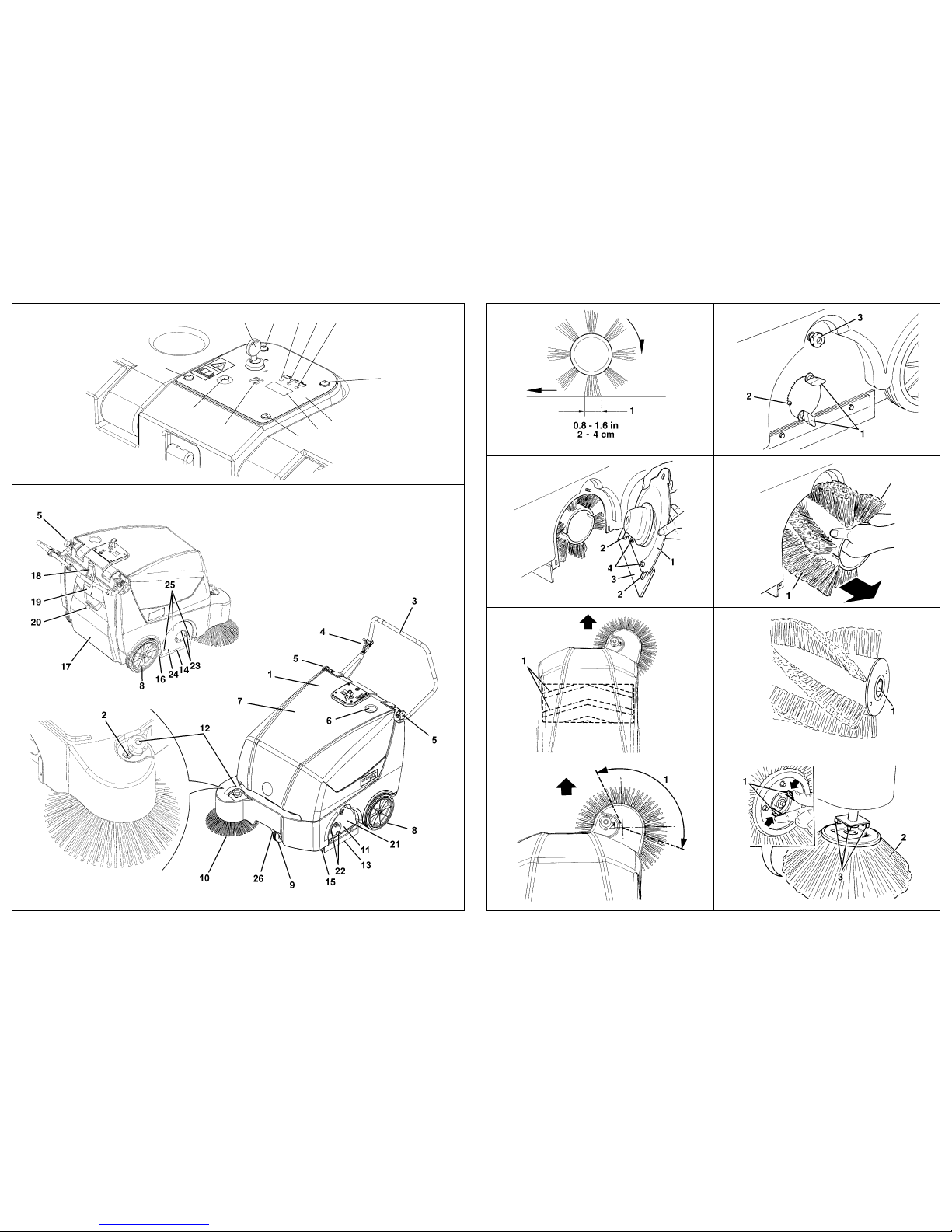
1. Turn the ignition key (2, Fig. B) to “0” position.
2. Open the hood (7, Fig. C).
3. The machine setting performed at the factory is for
lead – acid (WET) batteries. If the setting
corresponds to the chosen battery, go to the following
paragraph, otherwise perform the following
operations:
4. Disconnect the battery connector (3, Fig. U).
5. Remove the screws (9, Fig. B) and remove the
control panel (1, Fig. B) with care.
6. Install the jumper wire (1, Fig. T) on the “WET”
connectors (2, Fig. T) for lead batteries or on the
“GEL” connectors (3, Fig. T) for gel batteries.
7. Reinstall the control panel and tighten the screws (9,
Fig. B).
8. Reconnect the battery connector (3, Fig. U).
9. Close the hood (7, Fig. C).
Battery charger setting
1. Turn the key (2, Fig. B) to the “0” position; open the
hood (7, Fig. C) and switch the selector (9, Fig. U) to
(WET) for lead – acid batteries or to (GEL) for gel
batteries.
2. Install the battery on the machine according to the
diagram (10, Fig. U).
3. Proceed with charging the batteries (see the
procedure in the Maintenance chapter).
BEFORE START-UP
STARTING AND STOPPING THE MACHINE
At every start-up
1. Insert the ignition key (2, Fig. B) in the control panel;
turn it to the “I” position [without pulling the lever (4,
Fig. C)], then check that the green warning light (5,
Fig. B) turns on.
2. If the warning light becomes yellow or red (3 or 4,
Fig. B) turn the ignition key to “0” position and
remove it. Proceed with recharging the batteries (see
the procedure in the Maintenance chapter).
Starting the machine
1. Adjust the handlebar (3, Fig. C) by means of the
knobs (5), to reach a comfortable position.
2. Lower the side broom (10, Fig. C), disengage the
handle (12) from its latch (2) and lower the knob
(without turning it).
3. Turn the ignition key (2, Fig. B) to the “I” position
without pulling the drive lever (4, Fig. C).
4. Check that the green warning light (5, Fig. B)
(charged battery) turns on. If the warning light
becomes yellow or red (3 or 4, Fig. B), turn the
ignition key to the “0” position and then proceed with
recharging the battery. (See related chapter).
5. Pull the drive lever (4, Fig. C) with care until the
machine starts to move.
The speed is proportional to the pressure applied to
the drive lever (4, Fig. C).
WARNING!
Please pay strict attention when working
with sulfuric acid, as it is corrosive. If it
comes in contact with the skin or the eyes,
wash thoroughly with water and consult a
physician.
Battery has to be filled in a properly
ventilated area. Use protective gloves
NOTE:
Battery charger must be connected to the
batteries for machine to function.
WARNING!
Ensure that the hopper (17, Fig. C) is
correctly closed before starting up the
machine.
NOTE:
the side broom (10, Fig. C) can be lowered
also when it is running.

ToOrderPartsCall1-888-702-5326-https://monsterfloorequipmentparts.com
INSTRUCTIONS FOR USE
Blue 32 – 146 2301 000(1)2005-03 7
Stopping the machine
To stop the machine, release the drive lever (4, Fig. C)
completely and pull back on handle bar.
To stop the brooms from rotating, turn the key (2, Fig. B)
to “0” position.
To lift the side broom (10, Fig. C), lift the knob (12, Fig. C)
(without turning it) and align the latch with the slot in the
plastic chassis. Rotate the knob (12) forward to engage
the latch (2).
MACHINE OPERATION
1. Avoid stopping for a long time with the machine in the
same position and the brooms still rotating: this could
create unwanted marks on the floor.
2. To pick-up large debris, could be lifted the front skirt
by pulling the option lever; keep in mind that during
this operation the dust control of the machine will
decrease.
3. For proper machine operation, the dust filter must be
as clean as possible. To clean the filter while
sweeping proceeds as follows according to the type
of filter-shaker installed:
a) Manual filter - shaker: turn the ignition key in
the “0” position, then pull the handle (20, Fig. C)
outward until the end of the stroke is reached
and then release it: the return spring strikes the
dust filter frame and shakes it.
Repeat this operation several times. Turn the
ignition key in the “I” position to continue
working.
b) Electric filter-shaker (optional) press and hold
the filter-shaker button (8, Fig. B) for a few
seconds.
.
The hopper (17, Fig. C) should be emptied after each
working period and whenever it is full.
EMPTYING THE HOPPER
1. Release the drive lever to stop the machine.
2. Turn the ignition key (2, Fig. B) to the “0” position.
3. Disengage the hopper latch (18, Fig. C) by pulling
the bottom outward.
4. Using the hopper handle (19, Fig. C) remove the
hopper (17, Fig. C) from the machine and empty it.
5. Return the hopper to its normal operating position
and engage the hopper latch (18, Fig. C).
6. The machine is ready to start sweeping again.
AFTER MACHINE USE
When finished working:
1. Clean the filter using the manual filter shaker (20,
Fig. C) or the electric filter-shaker, if equipped, by
pressing the filter shaker button (8, Fig. B).
2. Empty the hopper (17, Fig. C) (see previous
paragraph).
3. Lift the side broom by lifting the knob (12, Fig. C).
4. Remove the ignition key (2, Fig. B) from the machine.
5. Ensure that the machine cannot move
independently.
6. Activate the optional brake pedal (26, Fig. C).
PUSHING THE MACHINE
The machine can be moved my pushing it both with the
ignition key (2, Fig. B) in the “0” and in the “I” positions.
MACHINE STORAGE
If you foresee that the machine will not be used for more
than 30 days, proceed as follows:
– Move the machine to a suitable indoor storage area.
– Disconnect the battery connector (3, Fig. U).
– Lift the machine so that the skirts, the main broom
and the wheels do not touch the ground.
– Disconnect the positive battery terminal (+) from the
positive battery (+) pole.
NOTE:
Repeat the operation at least every ten
minutes while working (according to the
dust conditions)
NOTE:
During this operation the electric motors
and all machine functions are automatically
stopped.
NOTE:
When the hopper and/or filter are full the
machine can not collect more dust and
debris.
CAUTION!
To avoid damaging the dust filter do not
sweep wet floors or ground.

ToOrderPartsCall1-888-702-5326-https://monsterfloorequipmentparts.com
INSTRUCTIONS FOR USE
8Blue 32 – 146 2301 000(1)2005-03
MAINTENANCE
The proper and safe machine operation is guaranteed by
careful and regular maintenance.
The following table sums up the scheduled maintenance
for the machine. The indicated periods can be subjected
to variations according to working conditions. These
variations must be defined by the person in charge of the
maintenance.
All periodic or extraordinary maintenance operations must
be performed by skilled personnel, or by an authorized
service center.
This manual describes only the easiest and most common
maintenance procedures.
SCHEDULED MAINTENANCE TABLE
(*): For the related procedure see “Service Manual”.
(1): Or before each start.
WARNING!
Maintenance operations are to be carried
out with the machine off, the ignition key
removed and (if required) the battery
disconnected.
Moreover, carefully read the instructions in
the Safety chapter.
NOTE:
For other maintenance procedures, see the
specific “Service Manual” that can be
consulted at the Kent Service Center.
Maintenance operation On delivery Every 10
hours Every 50
hours Every 100
hours Every 200
hours Every 400
hours
Battery liquid level check z z (1)
Drive belt visual inspection: main broom
drive z z (*)
Skirt height and operation check z z
Side and main broom height check z
Dust filter cleaning and integrity check z(1)
Electric filter-shaker (optional) operation
check z(*)
Nut and screw tightening check z(*)
Drive belt tensioner adjustment z(*)
Drive belt replacement: main broom drive z(*)
Main electric motor carbon brushes check
or replacement z(*)
Hood opening switch operation check z(*)

ToOrderPartsCall1-888-702-5326-https://monsterfloorequipmentparts.com
INSTRUCTIONS FOR USE
Blue 32 – 146 2301 000(1)2005-03 9
MAIN BROOM HEIGHT CHECK
1. Check the correct main broom height from the ground
(not carpet), proceeding as follows:
a. With the machine on level ground, keep the
machine stationary and allow the main broom to
rotate for several seconds.
b. Stop the main broom and move the machine.
c. Check that the main broom pattern (1, Fig. D),
proper width, is from 2 to 4 cm(0.8-1.6 in) on the
type of surface where the machine will be used.
d. If the pattern (1, Fig. D) is different, it is
necessary to adjust the broom height,
proceeding as described in step 2.
2. With the machine on level ground, activate the brake
pedal (26, Fig. C) (if equipped), or block the wheels
3. Turn the ignition key (2, Fig. B) to the “0” position.
4. Loosen the knobs (1, Fig. E) on both side of the
machine.
5. Using the knobs (1, fig. E) on both sides of the
machine, rotate the broom height adjuster indicator
(2) as necessary and then retighten the knobs (1).
6. Perform step 1 again to check the proper adjustment
of the main broom height from ground.
7. When the broom becomes too worn, adjustment is
no longer possible. Replace the broom following the
instructions in the following chapter.
MAIN BROOM REPLACEMENT
1. With the machine on level ground activate the brake
(26, Fig. C) (if equipped) or block the wheels.
2. Turn the ignition key (2, Fig. B) to the “0” position.
3. Loosen the knobs (1, Fig. E) on both sides of the
machine.
4. Move the broom height adjuster indicators (2, Fig. E)
until the broom reaches the maximum distance from
the ground. Retighten the knobs (1).
5. Open the cover (7, Fig. C).
6. On the left side of the machine, remove the knob (3,
Fig. E).
7. Remove the broom cover (1, Fig. F) by rotating the
top of the cover outward and lifting upward to
disengage the retainers (2).
8. Remove the broom (1, Fig. G) by sliding it out slowly.
9. Check that both broom hubs (4, Fig. R) are free of
dirt and foreign materials (cords, rope, etc.)
accidentally rolled up.
10. The new broom must be installed with the curve of
the bristle rows (1, Fig. H) as shown in figure (top
view).
11. Slide the new broom into the broom housing and
align the main broom hub (1, Fig. I) with the drive hub
(4, Fig. R).
12. Reinstall the broom cover (1, Fig. F) by engaging the
retainers (2) and aligning the plastic broom core with
the broom hub and pushing the top of the door
inward.
13. Retighten the knob (3, Fig. E).
14. Carry out the Main Broom Height Adjustment as
described in the previous paragraph.
NOTE:
Brooms with harder or softer bristles are
available. This procedure is applicable for all
types of brooms.
NOTE:
The indicator (2) does not have to be at the
same position on both sides of the machine;
the maximum difference allowed is 2
notches to obtain a correct broom pattern (1,
Fig. D) from 2 to 4 cm (0.8 – 1.6 in) as
described in step 1.
CAUTION!
A main broom pattern in excess of 4 cm (1.6
in) compromise the normal function of the
machine and can overheat the electrical
components, drastically reducing their life.
Pay particular attention when checking the
main broom height (broom pattern) and
never operate the machine outside the
specifications listed above.
CAUTION!
It is advisable to use protective gloves when
replacing the main or side broom because
there can be potentially harmful debris
between the bristles.
NOTE:
Brooms with harder or softer bristles are
available. This procedure is applicable to
each type of broom.

ToOrderPartsCall1-888-702-5326-https://monsterfloorequipmentparts.com
INSTRUCTIONS FOR USE
10 Blue 32 – 146 2301 000(1)2005-03
SIDE BROOM HEIGHT ADJUSTMENT
1. Check the correct height of the side broom from the
ground, by proceeding as follows:
2. With the machine on level ground, lower the side
broom by disengaging the side broom latch (2, Fig.
C).
3. Keep the machine stationary and allow the side
broom to rotate for a few seconds.
4. Stop the side broom and move the machine.
5. Check that the side broom pattern is as shown in
figure J. If it is different, adjust the broom height as
described in the following step.
6. Rotate the knob (12, Fig. C) clockwise or
counter-clockwise to adjust the broom height from
the ground.
7. Perform steps from 1 to 5 again to check the proper
adjustment of the side broom height from the ground.
8. When the broom becomes too worn, adjustment is
no longer possible. Replace the broom following the
instructions in the following paragraph.
SIDE BROOM REPLACEMENT
1. With the machine on level ground, activate the brake
(26, Fig. C) (if equipped) or block the wheels.
2. Turn the ignition key (2, Fig. B) to the “0” position.
3. Slide your hand under the side broom and press the
two tabs (1, Fig. K) inward and then push the broom
(2, Fig. K) downward to disengage it from the four
pins (3, Fig. K) on the side broom hub.
4. Install the new broom on the machine by aligning it on
the pins (3, Fig. K) and then pressing it onto the two
tabs (1, Fig. K).
5. Carry out the Side Broom Height Adjustment as
described in the previous paragraph.
DUST FILTER CLEANING AND INTEGRITY
CHECK
1. With the machine on level ground, activate the brake
pedal (26, Fig. C) (if present), or block the wheels.
2. Turn the ignition key (2, Fig. B) to the “0” position.
3. Disengage the hopper latch (18, Fig. C).
4. Using the handle (19, Fig. C) remove the hopper (17,
Fig. C) from the machine.
5. Rotate the filter clamp (1, Fig. L) upward
(approximately 90°) and let the top of the filter frame
(2) rotate outward.
6. Pull the dust filter (3, Fig. L) upward to remove it.
7. In a well-ventilated, outdoor area, clean the filter by
gently tapping the side of the filter (1, Fig. M),
opposite to the wire screen (2) on the ground.
8. Finish cleaning the filter by using compressed air (3,
Fig. M) of max. 6 bars (87 psi), blowing only from the
side protected by the wire screen (2, Fig. M).
According to the type of filter, take care of the
following cautions:
– Paper filter (standard): do not use water or
detergents to clean it; the filter can be damaged.
– Polyester filter (optional): to clean it, follow the
instructions mentioned in number 7 above. For
better cleaning, wash the filter with water and
non-foaming detergents. This type of washing will
clean the filter better, but it reduces the life of the
filter. The use of inadequate detergents can
damage the filter. Check the filtering medium body
for cuts or holes.
9. If necessary clean the filter compartment rubber seal
(4, Fig. L) along its perimeter and check its integrity.
If necessary replace it.
10. Install in the reverse order of removal.
NOTE:
Brooms with harder or softer bristles are
available. This procedure is applicable to
each type of broom.
NOTE:
Brooms with harder or softer bristles are
available. This procedure is applicable to
each type of brooms.
CAUTION!
It is advisable to use protective gloves when
replacing the main or side broom because
there can be potentially harmful debris
between the bristles.
NOTE:
Besides the standard paper filter, optional
polyester filters are available. The following
procedure is applicable to each type of filter.
NOTE:
Reinstall the filter with the wire screen (2,
Fig. M) facing the front part of the machine
(toward the fan (16, Fig. U)).

ToOrderPartsCall1-888-702-5326-https://monsterfloorequipmentparts.com
INSTRUCTIONS FOR USE
Blue 32 – 146 2301 000(1)2005-03 11
SKIRT HEIGHT AND OPERATION CHECK
1. With the machine on level and adequate ground to
check the skirt height, activate the brake pedal (26,
Fig. C) (if present), or block the wheels.
2. Turn the ignition key (2, Fig. B) to the “0” position.
Side skirt check
3. Check the side skirt (13 and 14, Fig C) integrity.
Replace the skirts when they have cuts (1, Fig N)
larger than 20 mm (0.75 in) or cracks (2) larger than
10 mm (0.5 in) (see the “Service Manual” for Skirt
Replacement).
4. Check that the side skirt (13 and 14, Fig. C) height
from the ground is within 0 – 3 mm (0 – 0.1in) (see
figure O). If necessary adjust the skirt height,
proceeding as follows:
Left skirt:
a. Open the hood (7, Fig. C), loosen the knob (3,
Fig. E) and remove the main broom access door
(1, Fig. F), lifting upward to disengage the
retainers (2).
b. Adjust the skirt (3, Fig. F) height by loosening
the two screws and using its slots (4, Fig. F).
c. Install in the reverse order of removal.
Right skirt:
a. Remove the Main Broom, as described in the
related chapter.
b. Remove the belt (12, Fig. U) from the pulley (14,
Fig. U); to facilitate the operation, rotate the
pulley (14, Fig. U) by rotating the fan (16, Fig. U).
c. Remove the screws (25, Fig. C) and the right cover
(24, Fig. C) together with the belt (12, Fig. U).
d. On the machine, adjust the skirt (1, Fig. S)
height by loosening the two screws (2, Fig. S)
and using its slots.
e. Install in the reverse order of removal.
Front and rear skirt check
5. Remove the main broom, as described in the related
paragraph.
6. Check the front and rear skirts (15 and 16 Fig. C) for
integrity.
7. Replace the skirts when they have cuts (1, Fig N)
larger than 20 mm (0.8 in) or cracks (2) larger than
10 mm (0.4 in) (see the “Service Manual” for Skirt
Replacement).
8. Verify that:
– the front skirt (1, Fig. P) drags lightly on the
ground (like in Figure P) and that it raised off the
ground.
– the rear skirt (1, Fig. O) must have an height from
ground from 0 up to 3 mm (0.1 in) (like in Fig. O).
9. If necessary, adjust the skirt height by loosening the
four screws and using its slots (3, Fig. R).
10. Pulling on the front skirt lifting lever (optional), verify
that the front skirt (1, Fig. Q) rotates upward
approximately 90° (like in Figure Q). Release, the
lever and verify that the skirt returns to its initial
vertical position and does not remain slightly
elevated. If necessary, see the installation
instructions for assembling, adjusting or replacing
the skirt lifting cable.
11. Install in the reverse order of removal.
BATTERY CHARGING
1. Drive the machine on level ground and activate the
brake pedal (26, Fig. C) (if present), or block the
wheels.
2. Turn the ignition key (2, Fig. B) to the “0” position.
3. Open the hood (7, Fig. C).
4. Only for lead-acid batteries, check the correct level
of electrolyte inside the battery; if necessary, fill
through the caps (8, Fig. U) to the required level.
5. Leave the caps (8) open for the next recharging.
6. Clean (if necessary) the upper surface of the battery.
7. Connect the battery charger electrical cable (5, Fig.
U) to the electrical supply (the system voltage and
frequency must be compatible with the battery
charger: see the Battery Charger Manual).
8. When the green warning light (11, Fig. U) turns on,
the battery is charged.
9. Disconnect the battery charger electrical cable (5,
Fig. U) from the electrical supply and put it back into
its housing in the machine.
10. Reassemble the battery caps (8, Fig. U)
11. Close the hood (1, Fig. U); the machine is ready to
be used.
WARNING!
Battery charging produces explosive
hydrogen gas. Charge the batteries only in a
well-ventilated area and far from open
flames or sparks.
Do not smoke during battery charging.
Keep the hood open while recharging the
battery.
WARNING!
Pay attention during battery recharging
because there can be battery liquid
leakage. The battery liquid is corrosive. If
it comes in contact with the skin or eyes
rinse thoroughly with water and consult a
physician.
NOTE:
For further information about the battery
charger (4, Fig. U) see the related Manual.
NOTE:
When the battery charger is connected to
the electrical supply, all machine functions
are automatically shut off.

ToOrderPartsCall1-888-702-5326-https://monsterfloorequipmentparts.com
INSTRUCTIONS FOR USE
12 Blue 32 – 146 2301 000(1)2005-03
SAFETY FUNCTIONS AND
TROUBLESHOOTING
HOOD SAFETY SWITCH
It is activated when the machine hood is lifted up: it stops
all machine functions.
In the case where the machine starts even when the hood
is open, contact an authorized Service Center or Retailer
for Service.
TROUBLESHOOTING
For further information consult the Service Manual at any
Kent Service Center.
SCRAPPING
Have the machine scrapped by a qualified dismantler.
Before scrapping the machine, remove the following
components:
1. Battery
2. Polyester dust filter
3. Main and side brooms.
4. Circuit board
TROUBLE SOLUTION
When the key is in the “I”
position, the machine does not
start.
Check that the connector 3, Fig. U
is properly connected.
Check that the hood is properly
closed.
Check the circuit breaker (6, Fig.
U).
Check the Electronic circuit fuse
(18, Fig. U) integrity
Check that the battery charger is
properly connected to the batteries
and/or the battery charger is not
plugged in to recharge the
batteries.
The side broom does not
operate Check the side broom fuse (7, Fig.
U) integrity
The machine operates only
when stationary, otherwise the
red warning light turns on.
Re-charge the battery. If the
problem persists, replace the
battery.
The circuit breaker (6, Fig. U)
trips frequently.
Check if the main broom pattern is
not wider than 4 cm (1.57 in)
Check that the machine is not
working on slopes higher than 2%
Check if debris is not blocking the
main broom rotation
The battery run time is low. Install a battery with greater
capacity. (Min. 140Ah)
NOTE:
As your machine has a battery charger
installed, the machine can not operate if the
charger is not on board. In case of battery
charger malfunction, contact an Authorized
Service Center.
CAUTION!
The removed components must be disposed
of properly and according to all applicable
laws.

ToOrderPartsCall1-888-702-5326-https://monsterfloorequipmentparts.com
MODE D’EMPLOI ET D’ENTRETIEN
Blue 32 – 146 2301 000(1)2005-03 1
INTRODUCTION....................................................................................................................... 2
BUT ET CONTENU DU MANUEL ..................................................................................................................... 2
DONNEES D’IDENTIFICATION ........................................................................................................................ 2
AUTRES MANUELS DE REFERENCE............................................................................................................. 2
PIECES DE RECHANGE ET ENTRETIEN ....................................................................................................... 2
MODIFICATIONS ET AMELIORATIONS .......................................................................................................... 2
SECURITE - PREVENTION DES ACCIDENTS ....................................................................... 2
SYMBOLES UTILISES ...................................................................................................................................... 2
INSTRUCTIONS GENERALES ......................................................................................................................... 3
DEBALLAGE ............................................................................................................................ 3
DESCRIPTION DE LA MACHINE ............................................................................................ 4
CAPACITES OPERATIONNELLES BALAYEUSE ............................................................................................ 4
CARACTERISTIQUES TECHNIQUES.............................................................................................................. 4
PROTECTIONS ELECTRIQUES....................................................................................................................... 5
ACCESSOIRES/OPTIONS................................................................................................................................ 5
UTILISATION............................................................................................................................ 5
CONTROLE / PREPARATION DE LA BATTERIE SUR UNE MACHINE NOUVELLE ..................................... 5
INSTALLATION DE LA BATTERIE ET ETABLISSEMENT DU TYPE DE BATTERIE (WET OU GEL)............ 6
AVANT LA MISE EN MARCHE ......................................................................................................................... 6
MISE EN MARCHE ET ARRET DE LA MACHINE............................................................................................ 6
MACHINE AU TRAVAIL .................................................................................................................................... 7
DECHARGEMENT DU CONTENEUR DECHETS ............................................................................................ 7
APRES L'UTILISATION DE LA MACHINE ........................................................................................................ 7
MOUVEMENT DE LA MACHINE PAR POUSSEE............................................................................................ 7
INACTIVITE PROLONGEE DE LA MACHINE .................................................................................................. 7
ENTRETIEN .............................................................................................................................. 8
PLAN D'ENTRETIEN PROGRAMME................................................................................................................ 8
CONTROLE HAUTEUR BROSSE CENTRALE ................................................................................................9
REMPLACEMENT BROSSE CENTRALE......................................................................................................... 9
REGLAGE HAUTEUR BROSSE LATERALE.................................................................................................. 10
REMPLACEMENT BROSSE LATERALE........................................................................................................ 10
NETTOYAGE FILTRE POUSSIERES ET CONTROLE INTEGRITE .............................................................. 10
CONTROLE HAUTEUR ET FONCTIONNEMENT VOLETS........................................................................... 11
CHARGEMENT DE LA BATTERIE ................................................................................................................. 11
FONCTIONS DE SECURITE ET DEPISTAGE DES PANNES .............................................. 12
INTERRUPTEUR DE SECURITE OUVERTURE COFFRE ............................................................................ 12
DEPISTAGE DES PANNES ................................................................................................... 12
MISE A LA FERRAILLE ......................................................................................................... 12

ToOrderPartsCall1-888-702-5326-https://monsterfloorequipmentparts.com
MODE D’EMPLOI ET D’ENTRETIEN
2Blue 32 – 146 2301 000(1)2005-03
INTRODUCTION
BUT ET CONTENU DU MANUEL
Ce manuel se propose de fournir au Client toutes les
informations nécessaires afin qu’il puisse utiliser la
machine correctement et la gérer dans la manière la plus
sûre. Il comprend des informations relatives à l’Aspect
Technique, le Fonctionnement, le Stockage de la
Machine, l’Entretien, les Pièces de Rechange et les
Conditions de Sécurité.
Ce Manuel s'adresse aux Opérateur aussi bien qu'aux
Techniciens préposés à l'Entretien de la machine.
Avant d’effectuer toute opération sur la Machine, les
Opérateurs et les Techniciens Qualifiés doivent lire
attentivement les instructions contenues dans ce texte. En
cas de doutes sur la correcte interprétation des
instructions, contacter le Fabricant pour avoir plus de
renseignements.
DONNEES D’IDENTIFICATION
Le Numéro de Série et le Modèle de Votre Machine sont
indiqués sur le marquage situé sous le coffre de la
machine. (20, Fig. U).
L’année de fabrication de Votre machine est indiquée
après le code de la date sur le numéro de série de la
machine. (A04 signifie janvier 2004)
Ces informations sont nécessaires lors de la commande
des pièces de rechange pour la machine et le moteur.
Utiliser l'espace ci-dessous pour noter les données
d'identification de Votre machine pour une référence
future.
.
AUTRES MANUELS DE REFERENCE
- Le Manuel du chargeur de batterie électronique, qui
est en dotation, doit être considéré comme une
partie intégrante de ce manuel.
En outre les suivants manuels sont disponibles:
- Manuel d’entretien consultable chez les Services
Après-vente Kent
- Catalogue des pièces de rechange, équipé avec la
machine.
PIECES DE RECHANGE ET ENTRETIEN
Pour toute nécessité concernant l’utilisation, l’entretien
extraordinaire et les réparations, si nécessaires, il faut
s’adresser au personnel qualifié ou directement aux
Centres de Service Après-vente Kent et il ne faut utiliser
que des pièces de rechange et accessoires originaux.
Pour l’assistance ou la commande de pièces de rechange
et accessoires, contacter l'organisation Kent en spécifiant
toujours le Modèle et le Numéro de série.
MODIFICATIONS ET AMELIORATIONS
Notre entreprise vise à un constant perfectionnement de
nos produits et se réserve le droit d’effectuer des
modifications et des améliorations, si nécessaires, sans
l’obligation de sa part de modifier les machines déjà
vendues.
Il est entendu que toute modification et/ou addition
d’accessoires doit toujours être approuvée et réalisée par
le Fabricant.
SECURITE - PREVENTION DES
ACCIDENTS
Kent utilise la symbologie suivante pour signaler les
conditions de danger potentielles. Lire toujours ces
informations avec attention et prendre les précautions
nécessaires pour protéger les personnes et les choses.
Aucun programme de prévention des accidents du travail
ne peut résulter efficace sans la totale collaboration de la
personne directement responsable du fonctionnement de
la machine. La plupart des accidents qui peuvent survenir
dans une entreprise, pendant le travail ou les
déplacements, sont dus à l’inobservance des plus simples
règles de prudence. Un utilisateur attentif et prudent est la
meilleure garantie contre les accidents du travail et se
révèle indispensable pour compléter n’importe quel
programme de prévention.
SYMBOLES UTILISES
Modèle MACHINE .......................................................:
Numéro de série MACHINE .........................................
DANGER !
Indique un danger qui comporte des
risques, même la mort, pour l’Utilisateur.
ATTENTION !
Il est utilisé pour avertir de l'exposition à un
risque d'accident aux personnes.
AVERTISSEMENT !
Indique un avertissement ou une remarque
sur des fonctions clé ou utiles. Prêter la plus
grande attention aux segments de texte
marqués par ce symbole.
CONSULTATION
Le Manuel doit être consulté avant toute
opération.

ToOrderPartsCall1-888-702-5326-https://monsterfloorequipmentparts.com
MODE D’EMPLOI ET D’ENTRETIEN
Blue 32 – 146 2301 000(1)2005-03 3
INSTRUCTIONS GENERALES
Les avertissements et précautions spécifiques suivants
informent sur les potentiels dangers de dommage à la
machine ou aux personnes.
– Porter la clé de mise en marche de la machine en
position d'arrêt, débrancher la batterie, avant
d'effectuer toute opération d'entretien/ réparation.
– Cette machine doit être utilisée exclusivement par un
personnel formé et autorisé. L’utilisation de la
machine est interdite aux enfants et aux personnes
handicapées.
– Tenir les étincelles, les flammes et les matériaux
fumants à distance des batteries. Des gaz tonnants
fuient pendant l'utilisation ordinaire.
– S'enlever tous les bijoux lorsqu'on travaille près de
composants électriques.
– Ne pas travailler sous la machine soulevée, sans des
supports fixes de sécurité convenables.
– Ne pas opérer avec cette machine en présence de
poudres, liquides ou vapeurs nuisibles, dangereux,
inflammables et/ou tonnants.
– En chargeant les batteries un gaz hydrogène très
tonnant est produit. Garder le coffre en position
ouverte pendant le cycle de rechargement des
batteries et effectuer l’opération exclusivement en
milieux bien aérés et loin de flammes libres.
– En cas d'installation à bord de batteries au plomb, ne
pas incliner la machine de plus de 30° depuis
l'horizontale pour aucune raison, car cela pourrait
provoquer des pertes de liquide très corrosif. Au cas
où il serait nécessaire d'incliner la machine pour
l'entretien, enlever les batteries au plomb.
– Avant d'effectuer toute activité d'entretien/ réparation,
lire avec attention toutes les instructions qui
concernent l'entretien/réparation.
– Prendre les précautions convenables afin que les
cheveux, les bijoux, les parties non adhérentes des
vêtements ne soient pas capturés par les parties en
mouvement de la machine.
– Ne pas fumer pendant le chargement des batteries.
– Ne pas laisser la machine sans surveillance et
s’assurer que la clé de mise en marche est enlevée
du tableau de bord et que la machine ne peut pas
bouger de façon autonome.
– Ne pas utiliser sur des surfaces dont le gradient est
supérieur à 2%.
– Ne pas laver la machine avec des jets d’eau directs
ou sous pression ou avec des substances corrosives.
Ne pas utiliser air comprimé pour le nettoyage
général de la machine.
– Ne pas utiliser la machine dans des milieux
particulièrement poussiéreux.
– Pendant l'utilisation de cette machine, faire attention
à sauvegarder l'intégrité des autres personnes.
– La température de stockage doit être comprise entre
0°C et +40°C.
– La température de travail de la machine doit être
comprise entre 0°C et +40°C.
– L’humidité doit être comprise entre 30% et 95%.
– Ne pas utiliser la machine comme moyen de
transport.
– Ne pas faire travailler les brosses lorsque la machine
est arrêtée pour ne pas endommager le plancher.
– En cas d’incendie utiliser un extincteur à poudre. Ne
pas utiliser d’eau.
– Ne pas heurter contre des étagères ou des
échafaudages, en particulier en présence de danger
de chute d’objets.
– Adapter la vitesse d'utilisation aux conditions
d’adhérence.
– Ne pas altérer pour aucune raison les protections
prévues pour la machine, respecter scrupuleusement
les instructions prévues pour l’entretien ordinaire.
– Ne pas enlever ou altérer les plaquettes placées sur
la machine par le Fabricant.
– S'assurer que les éventuelles anomalies de
fonctionnement de la machine ne dépendent pas du
manque d'entretien. En cas contraire demander
l'intervention de personnel autorisé ou d'un Service
Après-vente autorisé.
– En cas de remplacement de pièces demander les
pièces de rechange D’ORIGINE à un
Concessionnaire ou Revendeur autorisé.
– Afin de garantir la sécurité et le bon fonctionnement
de la machine, faire effectuer l'entretien programmé
prévu par le chapitre spécifique de ce manuel par le
personnel autorisé ou par un Service Après-vente
autorisé.
– La machine ne doit pas être abandonnée lors de la
mise à la ferraille, à cause de la présence de
matériaux toxiques (batteries, huiles, etc.), sujets à
des lois qui prévoient l’écoulement auprès de centres
spéciaux (voir à ce propos le chapitre Mise à la
ferraille).
– En conditions d’emploi conformes aux indications
d’utilisation correcte, les vibrations ne provoquent
pas de situations de danger. Le niveau de vibrations
de la machine est inférieur à 2,5 m/s2.
DEBALLAGE
Lors de la livraison de la machine, contrôler attentivement
que l’emballage en carton et la machine n’ont pas été
endommagés pendant le transport. Si le dommage est
évident, garder l’emballage de façon qu’il puisse être
visionné par le Transporteur qui l'a livré. Le contacter
immédiatement pour remplir une demande de
dommages-intérêts.
Contrôler toujours que les composants suivants se
trouvent toujours avec Votre machine:
1. Documentation technique: Manuels d'Emploi et
d'Entretien de la balayeuse et du chargeur de
batterie électronique, Catalogue des pièces de
rechange
2. Fusible brosse latérale (1)
3. Câbles et bornes de batterie de rechange
4. Fusible électronique (1)
DANGER!
ATTENTION !

ToOrderPartsCall1-888-702-5326-https://monsterfloorequipmentparts.com
MODE D’EMPLOI ET D’ENTRETIEN
4Blue 32 – 146 2301 000(1)2005-03
DESCRIPTION DE LA MACHINE
CAPACITES OPERATIONNELLES
BALAYEUSE
La balayeuse est conçue et fabriquée pour le nettoyage
(balayage) de planchers lisses et solides, de moquette
rase, en milieux civils et industriels, et pour le collectage
de poussières non dangereuses et déchets légers, en
condition de complète sécurité, par un Opérateur qualifié.
Tableau de bord et commandes
(Voir Fig. B)
1. Tableau de bord
2. Clé de mise en marche
3. Témoin lumineux de batterie déchargée
4. Témoin lumineux de batterie presque complètement
déchargée
5. Témoin lumineux de batterie déchargée
6. Afficheur données (Display)
7. Bouton-poussoir de sélection sur l'afficheur :
compteur horaire / compteur horaire et minuteur /
tension de la batterie (V)
8. Fusible secoueur électrique (optionnel)
9. Vis de fixation tableau
Vue extérieure générale
(Voir Fig. C)
1. Plaquette de Numéro de série / données techniques
2. Dispositif de retenue brosse latérale
3. Guidon
4. Levier d’activation
5. Poignées pour le réglage d’inclination du guidon
6. Porte-objet
7. Coffre
8. Roues arrière sur axe fixe
9. Roue avant tournante
10. Brosse latérale
11. Brosse centrale
12. Poignée pour le soulèvement et le réglage hauteur
brosse latérale
13. Volet latéral gauche
14. Volet latéral droit
15. Volet avant
16. Volet arrière
17. Conteneur déchets
18. Crochet du conteneur déchets
19. Poignée du conteneur déchets
20. Poignée du secoueur manuel
21. Portillon amovible de la brosse centrale
22. Régulateur gauche de la hauteur de la brosse
centrale
23. Régulateur droit de la hauteur de la brosse centrale
24. Portillon droit de la brosse centrale
25. Vis de fixation portillon droit de la brosse centrale
26. Frein à pédale sur la roue avant (optionnel)
Sous le coffre
(Voir Fig. U)
1. Coffre (en position ouverte)
2. Batteries
3. Connecteur de batterie
4. Chargeur de batterie électronique
5. Câble électrique de branchement du chargeur de
batterie au réseau de courant
6. Coupe-circuit
7. Fusible brosse latérale
8. Bouchons de batterie (au plomb)
9. Sélecteur de la batterie au plomb (WET) ou au gel
(GEL) positionné sur le chargeur de batterie
électronique
10. Schémas d’installation de la batterie
11. Témoin lumineux de batterie déchargée
12. Courroie de la brosse centrale
13. Courroie de traction
14. Poulie de transmission pour brosse centrale
15. Poulie de transmission pour roues arrière
16. Ventilateurs
17. Moteur électrique principal
18. Fusible circuit de contrôle
19. Interrupteur de sécurité ouverture coffre
20. Plaquette de Numéro de série/données techniques
21. Chaîne de mise a terra
CARACTERISTIQUES TECHNIQUES
Dimensions Valeurs
Largeur de nettoyage
(sans brosse latérale) 600 mm (23,62 in)
Largeur de nettoyage
(avec brosse latérale) 791 mm (31,14 in)
Longueur machine 1070 mm (42,18 in)
Largeur machine,
sans brosse latérale 773 mm (30,43 in)
Hauteur avec guidon baissé 836 mm (32,91 in)
Hauteur minimum du sol 40 mm (1,6 in)
Hauteur guidon 926,46 mm (36,5 in)
Dimensions brosse centrale ø 245 x 600 mm
(9,65x23,62 in)
Dimensions brosse latérale ø 347 mm (13,7 in)
Vitesse avec force de poussée
maximum 4,4 Km/h (2,7 mph)
Pente maximum surmontable 2%
Capacité conteneur déchets 50 l (1,7 ft3)
Poids total machine sans
batterie 99,82 Kg (220,1 lb)
Roue avant, de direction ø 125/37,5-50 mm
(4,92/1,48-1,97 in)
Roues arrière, de traction ø 250 x 50 mm
(ø9,84x1,97 in)
Moteur électrique 600W (0,8 Ch)
Niveau pression sonore
pondérée (LpA) 64 dB(A)
Batteries
- Au plomb, avec électrolyte acide (WET)
- Au gel, hermétique (GEL)
L’établissement de fabrication de la machine est adéquat
pour les batteries au plomb (WET).
Tension batterie 12 V
Capacité batteries utilisables Max. 240 Ah
Dimensions logement batteries 398x262x283
(15,7x10,3x11,1 in)
REMARQUE:
toutes les références à en avant, en arrière,
avant, droite, gauche ou arrière indiquées
dans ce manuel doivent être considérées
comme référées à l'opérateur en position de
conduite, les mains sur le guidon (3, Fig. C).

ToOrderPartsCall1-888-702-5326-https://monsterfloorequipmentparts.com
MODE D’EMPLOI ET D’ENTRETIEN
Blue 32 – 146 2301 000(1)2005-03 5
Aspiration et filtrage poussières
Filtre poussières,
en papier de 5-10 µm 2 m2 (22 ft2)
Secoueur électrique (optionnel) 12V, 30W
Dépression logement brosse
centrale 4 mm H2O
(0,63 in H2O)
Schéma
Schémas électriques, pour les équipements optionnels
différents (Fig. V).
CH1 Chargeur de batterie
CN1 Connecteur de batterie
CN2 Connecteur du chargeur de batterie
EB1 Carte électronique
ES1 Télérupteur
F1 Fusible restaurable 70A
F2 Fusible brosse latérale 15A
F3 Fusible signal 10A
M1 Moteur électrique principal
M2 Moteur brosse latérale
M3 Moteur secoueur
R1 Relais secoueur
SW1 Interrupteur clé
SW2 Interrupteur de sécurité ouverture coffre
SW3 Interrupteur secoueur (optionnel)
Code de couleurs
BK Noir
BU Bleu
BN Marron
GN Vert
GY Gris
OG Orange
PK Rose
RD Rouge
VT Violet
WH Blanc
YE Jaune
PROTECTIONS ELECTRIQUES
Coupe-circuit: 6, Fig. U
Fusible brosse latérale: 7, Fig. U
Fusible circuit de contrôle 18, Fig. U
ACCESSOIRES/OPTIONS
Outre les composants présents dans le modèle standard,
la machine peut être équipée avec les accessoires
optionnels suivants, selon l'emploi spécifique de la
machine:
1. Batterie(s) au gel
2. Brosses centrale et latérale avec poils plus ou moins
durs par rapport au standard
3. Filtre poussières en polyester antistatique et en
polyester BIA C
4. Secoueur électrique
5. Roue avant avec frein à pédale
6. Types différents de caoutchouc pour volets
7. Levier volet avant
Pour de plus amples informations relatives aux
accessoires optionnels susmentionnés, adressez- Vous à
Votre Revendeur de confiance.
UTILISATION
Au moment de la lecture de ce manuel, l'opérateur doit
comprendre le signifié de ces symboles.
Ne pas couvrir les adhésifs et les remplacer
immédiatement en cas d'endommagement.
CONTROLE / PREPARATION DE LA
BATTERIE SUR UNE MACHINE
NOUVELLE
La machine requiert une batterie de 12 V ou deux batteries
de 6 V branchées selon le schéma (10, Fig. U).
La machine peut être fournie selon une des méthodes
suivantes:
a. Avec batterie (au plomb ou au gel) installée sur la
machine et prête pour l’utilisation.
b. Avec batterie (au plomb) installée sur la machine,
mais sans l’électrolyte liquide.
c. Sans batterie
Selon le type d’équipement, effectuer les opérations
suivantes.
a. Batterie (au plomb ou au gel) équipée et déjà
installée sur la machine et prête pour
l’utilisation.
1. Soulever le coffre (7, Fig. C) de la machine et vérifier
que la batterie est branchée à la machine par le
connecteur spécifique (3, Fig. U).
2. Baisser le coffre en s’assurant de sa fermeture
correcte (la machine doit se présenter comme
montré dans la Fig. C).
3. Insérer sur le tableau de bord la clé de mise en
marche (2, Fig. B); la tourner en position “I” (sans
tirer le levier 4, Fig. C).
Si le témoin lumineux vert s’allume (5, Fig. B), la
batterie est prête pour l’utilisation.
En cas contraire, il est nécessaire d’effectuer le
chargement de la batterie (voir procédure au
chapitre Entretien).
b. Batterie (au plomb) équipée et déjà installée sur
la machine mais à sec (c’est à dire sans
électrolyte liquide).
1. Soulever le coffre (7, Fig. C) de la machine.
2. Enlever les bouchons (8, Fig. U) de la batterie.
ATTENTION !
Des adhésifs appliqués en certains points
de la machine indiquent:
- DANGER
- ATTENTION
- AVERTISSEMENT
- CONSULTATION
REMARQUE:
Connecter le chargeur de batterie aux
batteries pour mettre en fonction la
machine.
ATTENTION !
Faire attention pendant l’utilisation d’acide
sulfurique, à cause de sa corrosivité; en cas
de contact avec la peau ou les yeux, laver et
rincer abondamment à l’eau et consulter un
médecin. Les batteries doivent être remplies
dans un milieu bien aéré. Utiliser les gants
de protection.

ToOrderPartsCall1-888-702-5326-https://monsterfloorequipmentparts.com
MODE D’EMPLOI ET D’ENTRETIEN
6Blue 32 – 146 2301 000(1)2005-03
3. Remplir les éléments de la batterie avec acide
sulfurique pour batteries (densité de 1,27 à 1,29 Kg
à 25°C) selon les instructions spécifiées dans le
Manuel d’emploi de la batterie.
La quantité correcte de solution acide à insérer est
indiquée dans le Manuel d’emploi de la batterie.
4. Laisser reposer la batterie et remplir les éléments
avec solution d’acide sulfurique, selon les
instructions spécifiques indiquées dans le Manuel
d’emploi de la batterie.
5. Effectuer le chargement de la batterie (voir
procédure au paragraphe Entretien).
c. Batterie non équipée
1. Acheter une batterie adéquate (voir paragraphe
Caractéristiques Techniques et le schéma 10, Fig.
T).
S’adresser aux revendeurs de batteries qualifiés
pour le choix et l’installation.
2. Procéder à l’établissement de la machine et du
chargeur de batterie (si installé) en fonction du type
de batterie choisi.
3. Effectuer l’installation de la batterie.
INSTALLATION DE LA BATTERIE ET
ETABLISSEMENT DU TYPE DE BATTERIE
(WET OU GEL)
En fonction du type de batterie choisi (au plomb ou au gel),
il est nécessaire d’effectuer l’établissement relatif de la
carte électronique de la machine et du chargeur de
batterie en opérant selon les indications suivantes:
Etablissement machine - tableau de bord
1. Tourner la clé en position “0” (2, Fig. B)
2. Soulever le coffre (7, Fig. C).
3. L’établissement de fabrication de la machine est
adéquat pour les batteries au plomb (WET). Si cet
établissement correspond au type de batterie
acheté, passer au paragraphe suivant. En cas
contraire, effectuer les opérations suivantes :
4. Débrancher le connecteur (3, Fig. U).
5. Dévisser les vis (9, Fig. B) et enlever le tableau de
bord (1, Fig. B) avec soin.
6. Positionner la barrette (1, Fig. T) sur les connecteurs
(3, Fig. T) “GEL” pour batterie au gel.
7. Remonter le tableau de bord et serrer les vis (9, Fig.
B).
8. Brancher le connecteur (3, Fig. U) de nouveau.
9. Fermer le coffre (7, Fig. C).
Etablissement chargeur de batterie
1. Tourner la clé en position “0” (2, Fig. B) ; soulever le
coffre (7, Fig. C) et positionner le sélecteur (9, Fig. U)
en position “WET” pour batterie au plomb et en
position “GEL” pour batterie au gel.
2. Installer la batterie sur la machine en suivant le
schéma (10, Fig. U).
3. Effectuer le chargement de la batterie (voir
procédure au paragraphe Entretien).
AVANT LA MISE EN MARCHE
MISE EN MARCHE ET ARRET DE LA
MACHINE
A toute mise en marche
1. Insérer la clé de mise en marche sur le tableau de
bord (2, Fig. B); la tourner en position “I” [sans tirer le
levier (4, Fig. C)], donc vérifier l’allumage du témoin
lumineux vert (5, Fig. B).
2. Dans le cas où le témoin lumineux jaune ou rouge
s’allumerait (3 ou 4, Fig. B), repositionner la clé en
position “O” et l’enlever. Effectuer donc le
rechargement de la batterie (voir procédure au
chapitre Entretien).
Mise en marche de la machine
1. Régler le guidon (3, Fig. C) à l’aide des poignées (5),
selon les exigences du conducteur.
2. Baisser la brosse latérale (10, Fig. C) baissant (sans
la tourner) la poignée (12) après avoir décroché son
dispositif de retenue (2).
3. Tourner la clé de mise en marche (2, Fig. B) en
position “I” sans tirer le levier d’activation (4, Fig. C).
4. Vérifier l’allumage du témoin lumineux vert (5, Fig. B)
(batterie chargée) Dans le cas où le témoin lumineux
jaune ou rouge s’allumerait (3 ou 4, Fig. B),
repositionner la clé en position “0” et effectuer le
rechargement de la batterie. (Voir chapitre relatif).
5. Tirer avec soin le levier d’activation (4, Fig. C)
jusqu’à ce que la machine bouge. La vitesse
d’avance est proportionnelle à la pression exercée
sur le levier d’activation (4, Fig. C).
ATTENTION !
S’assurer que le conteneur déchets (17, Fig.
C) est correctement fermé avant la mise en
marche de la machine.
REMARQUE:
la brosse latérale (10, Fig. C) peut être
baissée et soulevée même pendant son
fonctionnement.
Table of contents
Languages:
Other KENT Blower manuals
Popular Blower manuals by other brands

Ryobi
Ryobi RY421021 Operator's manual

Husqvarna
Husqvarna 115 31 90-95 Operator's manual

GreenWorks
GreenWorks 2400807AU Operator's manual

Craftsman
Craftsman 358.794200 Operator's manual

Poulan Pro
Poulan Pro FL1500 Operator's manual

Gardner Denver
Gardner Denver Sutorbilt Legend P Series Operating and service manual