CONTENTS
SAFETY
PRECAUTIONS.
..........c:cesecceeseseeeeeeeeeeeerneeees
1
IMPORTANT
NOTICE
.........::ccsccessseeseeeceeseeeeneresaetenereee
1
INTRODUCTION
..........csccesccsssecessessscssecesesesneesaresneeaes
1
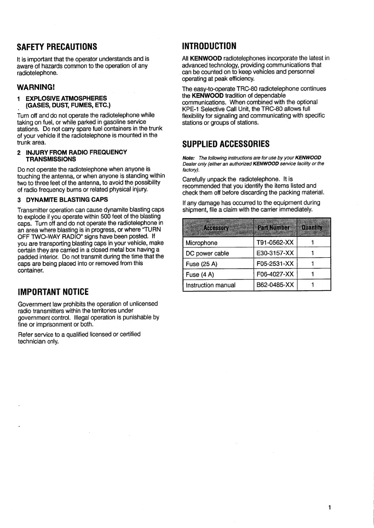
SUPPLIED
ACCESSORIES
..........ccccccscssseestesseeseeeeees
1
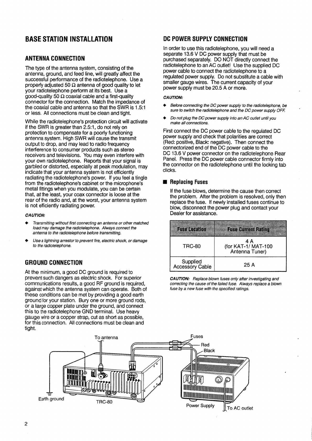
BASE
STATION
INSTALLATION
..........c:ccesscesseeseeeees
2
ANTENNA
CONNECTION
.......cccsseeectseseeeeeeseeees
2
GROUND
CONNECTION
.........ccccsscsscessersseesseeteees
2
DC
POWER
SUPPLY
CONNECTION
............000+
2
Replacing
FuS€S
...........eeeeeseeeeeseeeseeeeeeneeeseees
2
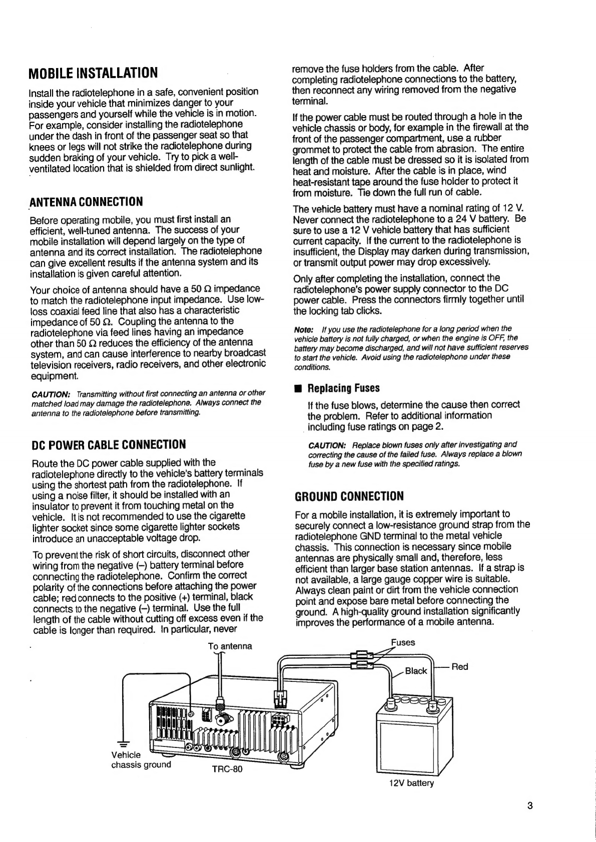
MOBILE
INSTALLATION
..........::ccssccssssssesessessseeseeeeneres
3
ANTENNA
CONNECTION
.........cscccsereessesereseeeseeeees
3
DC
POWER
CABLE
CONNECTION
........:::ceceeees
3
Replacing
FUSES
........ecseseessceseeeeseeeseeeeeeeeneeees
3
GROUND
CONNECTION
...........cccesseestesssersreeseeee
3
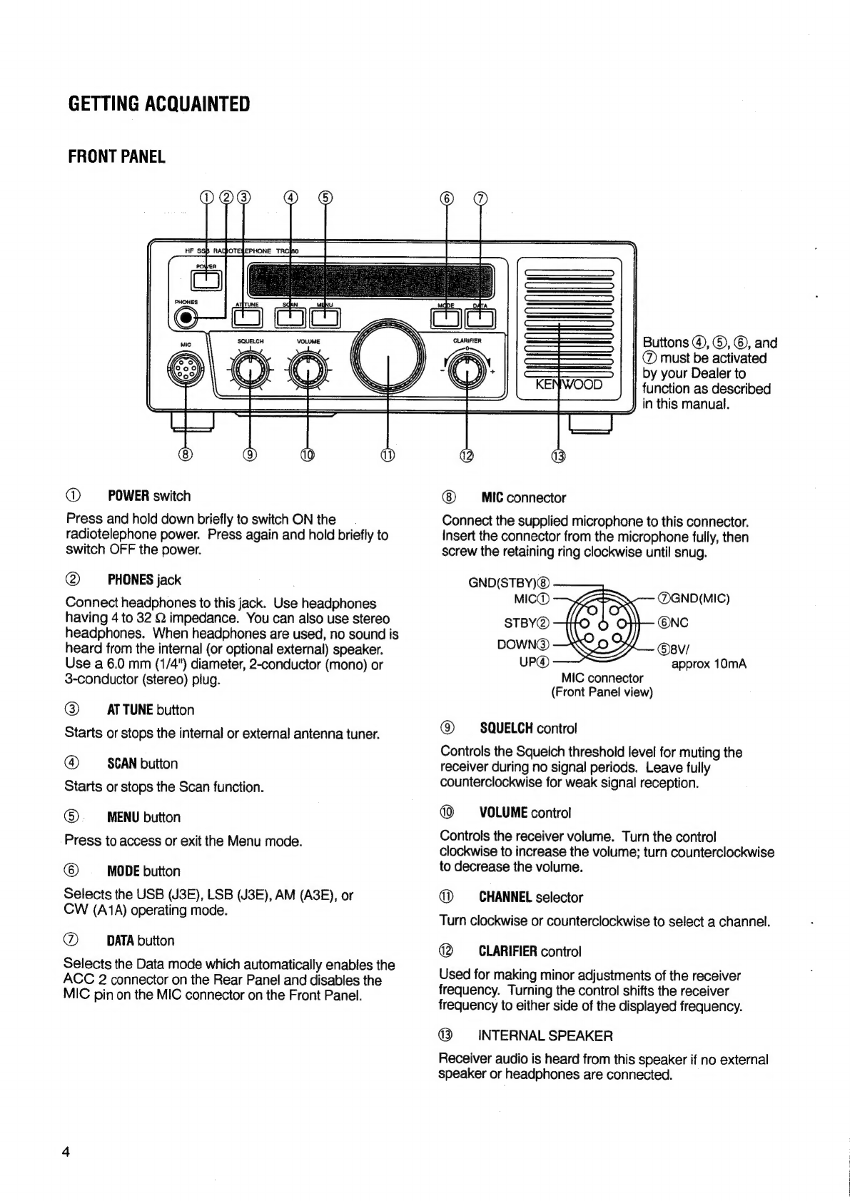
GETTING
ACQUAINTED
..........eceecssescesersecesnseeneneneees
4
FRONT
PANEL
...........ccccccseecsscesseeseessecesenesseeeseesees
4
REAR
PANEL
..........::ccsscssseesseeesseessesseesseeseseeeeesnees
5
DISPLAYS
escsdeecscdesccrtecstecsots
ac
vases
te
ceeses
dees
6
MICROPHONE
.........:.c::ccsscccssecsecsseeseeeseeecseesseeesees
7
OPERATING
BASICS
........cceecssecscesseessecseeseeeeneesreees
7
SWITCHING
POWER
ON/OFF
........::csceseceseeeteees
7
ADJUSTING
VOLUME
.........cscesesecetecseseeeeeeeeeeseeens
7
ADJUSTING
SQUELCH
......
ce
eeeeeeeeeeeseecreeereeereee
7
SELECTING
A
CHANNEL...
.ceceeceeeseeeeeeeteeeeneeee
8
SELECTING
A
MODE
........eeeecsecsseseeeseceescerneeeeeeees
8
TRANSMITTING
uu...
cecccseeesceescesseesseesseeteneteneeeenes
8
Changing
Transmit
POWE?
..........cceeeeeseeseeeeeees
8
VOICE
MOdES
........eeeeecesececerscenseenteeteeeeesetseeneteees
8
VOX
(Voice-operated
Transmit)
.............
cere
8
QW:
MOG
vssseviccesececsssccsssteassoceudicesesctdvstuessooesvene
9
DATA
OPERATION
istesssscsscessassecvsscsdeceslassebeatvesceedsiees
9
PSKMODE
sisiscdecdssstesnscei
hoe
naneciieeectdaesetecse
dette
9
ASK.
MODE
scscckcvnsceesteavssseedesavadeedvenendectdasddavavestees
9
MENU
SETUP
si
cgec
sectitecs
Seti
letiedivetecstetes
acetic
10
CHANGING
MENU
SETTINGS
.......
ec
eeeeeseseeeees
10
MENU
CONFIGURATION
..........s:ccscceseeseessceeserens
10
MEMORY
BACKUP.
........:ccsccccceessessecsceeseeecerecseeseeeaes
10
SCAN
sscssk
cele
vei
ssetediceathetatldwae
ists
Ravtece
aezenetetes
11
BUSY
FREQUENCY
STOP
.......ceecceeescereeeereeees
11
Scan
Resume
Methods
...........:::esecceeseeseneeeeees
11
CHANNEL
LOCKOUT
............:cccsccescestecseceereeseeees
11
STARTING/
STOPPING
SCAN
.........:csccesseeeesees
am]
NOISE
BLAMKER
..........cccccscessesseesseeseessaeesaeesseeeeeeaes
11
GLARIPIER
3:
ssccdestabccetscccseathccsceanetvavstonstunses
sacuSueeybeduns
11
KPE-1
SELECTIVE
CALL
UNIT
(OPTIONAL)
...........
11
MANUAL
CALLING
..........ccccesceeeescecseesseeseesneeees
12
MEMORY
CALLING
..........::cscccsssesssesteesseessreeeeesees
12
REGEIVING
oissesdists.
iesstisssistetetesectdoeeceasbenccatiinee
12
CHANGING
IDENTIFICATION
CODEG...............
13
CHANGING
CHARACTER
MESSAGES
.............
13
AUTOMATIC
ANTENNA
TUNER
....ecsssseseccressssssssson
13
PRESETTING
(KAT-2
INTERNAL
TUNER)..........
13
KAT-2
INTERNAL
TUNER
(OPTIONAL)..........0+0
13
KAT-1/
MAT-100
EXTERNAL
TUNER
(OPTIONALY
(.2accddiardunciamionaurtulnians
13
COMPUTER
=
RADIOTELEPHONE
INTERFACE..sssssssssssssssssssscsssssssssssessesssesssssenesnssssssen
14
COMMUNICATION
PARAMETERS
......sssssseesseee
14
HARDWARE
DESCRIPTION
....ssssssssssssessssessesseee
14
MAINTENANCE
...ssssssssssssscssssescsssesssesssssenssenesseeseseses
15
SERVICE
totes
enti
te
ere
Ean
15
SERVICE
NOTE
siiscicansaumiewisutucstauainn
15
CLEANING
a2
he
8c
ater
cnt
tech
oe
nenak
Sashuch
ch
15
TROUBLESHOOTING
uvesssssesssssssssessscesssssssssssenee
16
ACCESSORY
CONNECTIONS
o...ccccsssssseceetesssssesen
17
COMPUTER
INTERFACE
(ACC
1)
..ssssssssssssssseen
17
PC-1A
PHONE
PATCH
CONTROLLER
(AGO
2)
ied
nncetedsesccdis
17
ANTENNA
TUNER
(AT)
...ssssssssssssescsevssssssssseseeeeee
17
DATA
EQUIPMENT
INTERFACE
(ACC
2)..........
18
OHANNEL
MEMO
sate
isl
ccvsssccaschencnnueiconsaaia
19
APPENDIX
wigtiptinciencaiel
ed
iat
ones
Al
CONTROL
OPERATION
...ssssssssssssssssssssssssseseeeeee
At
COMMANDS
sfc
cccat
entre
esa.
aati
At
COMMAND
DESCRIPTION
.....ssssssssssssssssseeseeeeee
At
PARAMETER
DESCRIPTION
......csssssssssssseseeeeee
At
TERMINATOR
ocscescseccsssssssssssssssssssssssonsnsssceeesece
A2
TYPES
OF
COMMANDS
....sssssssssssssssssssssssesesseee
A2
COMPUTER
CONTROL
COMMANDS
.......s.sss00
A3
ERROR
MESSAGES
......sssssssssssssesesseseeeseeesees
A3
COMMAND
USE
PRECAUTIONS
.....sssssssssseseeee
A3
READING
COMMAND
TABLES
...ssssssssssssesssseeeees
A4
COMMAND
TABLES
....ssssssssssssssssssssssssssasesssessese
A4